Page 65 of 513
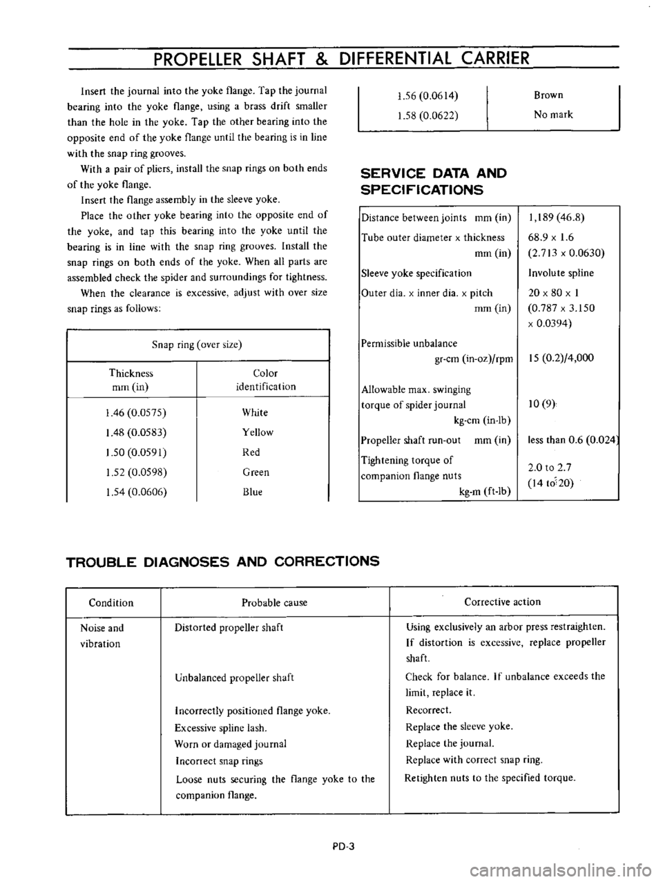
AUTOMATIC
TRANSMISSION
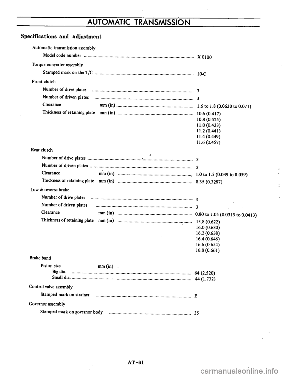
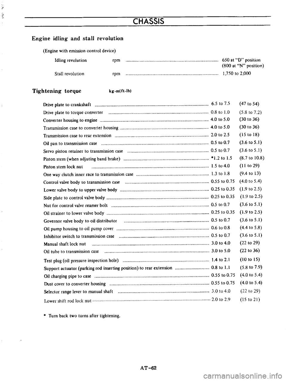
Specifications
and
adjustment
Automatic
transmission
assembly
Model
code
number
Torque
converter
assembly
Stamped
mark
on
the
TIC
Front
clu
tch
Number
of
drive
plate
Number
of
driven
plates
Clearance
Thickness
of
retaining
plate
Rear
clutch
Number
of
drive
plates
Number
of
driven
plate
Clearance
Thickness
of
retaining
plate
Low
reverse
brake
Number
of
drive
plates
Number
of
driven
plates
Clearance
Thickness
of
retaining
plate
Brake
band
Piston
size
Big
dia
Small
dia
Control
valve
assembly
Stamped
mark
on
trainer
Governor
assembly
Stamped
mark
on
governor
body
mm
in
mm
in
mm
in
mm
in
mm
in
mm
in
mm
in
AT
61
x
0100
IO
C
3
3
1
6
to
1
8
0
0630
to
0
071
10
6
0
417
10
8
0
425
11
0
0
433
11
2
0
441
II
4
0
449
11
6
0
457
3
3
1
0
to
1
5
0
039
to
0
059
8
35
0
3287
3
3
0
80
to
1
05
0
0315
to
0
0413
15
8
0
622
16
0
0
630
16
2
0
638
16
4
0
646
16
6
0
654
16
8
0
661
64
2
520
44
I
732
E
35
Page 66 of 513

CHASSIS
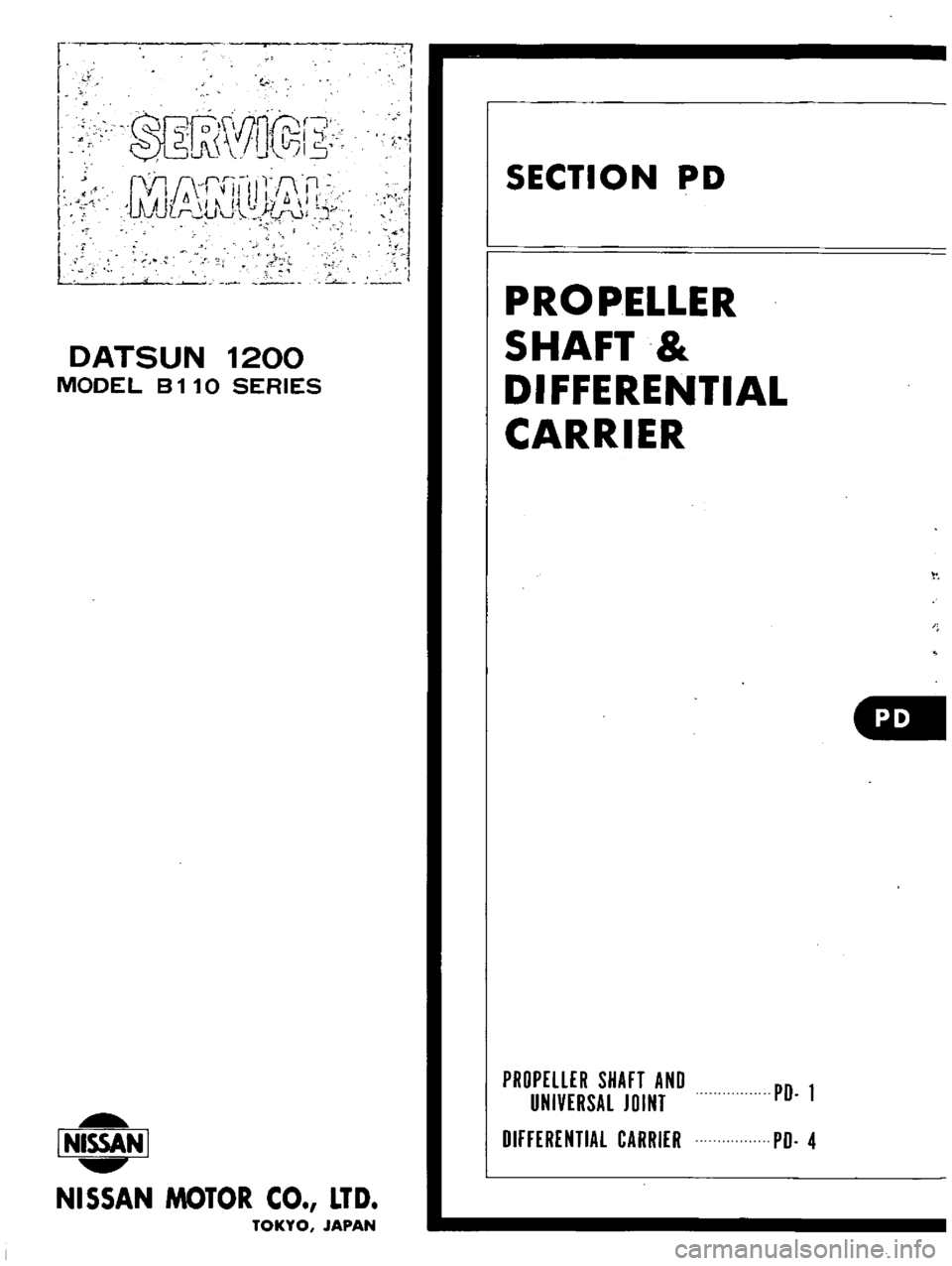
Engine
idling
and
stall
revolution
Engine
with
emission
control
device
Idling
revolution
rpm
650
at
0
position
800
at
N
position
1
750
to
2
000
Stall
revolution
rpm
Tightening
torque
kg
m
ft
Ib
Test
plug
oil
pressure
inspection
hole
Support
actuator
parking
rod
inserting
position
to
rear
extension
Oil
charging
pipe
to
case
Dust
cover
to
converter
housing
Selector
range
lever
to
manual
shaft
Lower
shift
rod
lock
nut
6
5
t07
5
47
to
54
0
8
to
1
0
5
8
to
7
2
4
0
to
5
0
30
to
36
4
0
to
5
0
30
to
36
2
0
to
2
5
15
to
18
0
5
to
0
7
3
6
to
5
1
0
5
to
0
7
3
6toS
I
1
2
to
1
5
8
7
to
10
8
1
5
to
4
0
II
to
29
1
3
to
1
8
9
4
to
13
0
55
to
0
75
4
0
to
5
4
0
25
to
0
35
1
9
to
2
5
0
25
to
0
35
1
9
to
2
5
0
5
to
0
7
3
6
to
5
I
0
25
to
0
35
1
9
to
2
5
0
5
to
0
7
3
6
to
5
1
0
6
to
0
8
4
4
to
5
8
0
5
to
0
7
3
6
to
5
1
3
0
to
4
0
22
to
29
3
0
to
5
0
22
to
36
14
to
2
1
10
to
15
0
8
to
l
l
5
8
to
7
9
0
55
to
0
75
4
0
to
5
4
0
55
to
0
75
4
0
to
5
4
3
0
to
4
0
22
to
29
2
0
to
2
9
15
to
21
Drive
plate
to
crankshaft
Drive
plate
to
torque
converter
Converter
housing
to
engine
Transmission
case
to
converter
housing
Transmission
case
to
rear
extension
Oil
pan
to
transmission
case
Servo
piston
retainer
to
transmission
case
Piston
stem
when
adjuting
band
brake
Piston
stem
lock
nut
One
way
clutch
inner
race
to
transmission
case
Control
valve
body
to
transmission
case
Lower
valve
body
to
upper
valve
body
Side
plate
to
control
valve
body
Nut
for
control
valve
reamer
bolt
Oil
strainer
to
lower
valve
body
Governor
valve
body
to
oil
distributor
Oil
pump
housing
to
oil
pump
cover
Inhibitor
switch
to
transmh
sion
case
Manual
shaft
lock
nut
Oil
tube
to
transmission
case
Turn
back
two
turns
after
tightening
AT
62
Page 67 of 513
r
r
QRr
S
IJ
lrll
r
W
bI15
I
Q
ll
rrll
l
0
fl
AU
1
i
L
Ill
J
cr
U
J
r
Jj
I
DATSUN
1200
MODEL
B
11
0
SERIES
L
NISSAN
I
NISSAN
MOTOR
CO
LTD
TOKYO
JAPAN
I
I
i
I
I
I
SECTION
PD
PROPELLER
SHAFT
DIFFERENTIAL
CARRIER
PROPELLER
SHAFT
AND
UNIVERSAL
JOINT
DIFFERENTIAL
CARRIER
PD
1
PD
4
Page 68 of 513

PROPELLER
SHAFT
DIFFERENTIAL
CARRIER
PROPELLER
SHAFT
AND
UNIVERSAL
JOINT
CONTENTS
DESC
R
I
PTI
ON
REMOVAL
DISASSEMBL
Y
INSPECTION
ASSEMBL
Y
PD
PD
2
PD
2
PD
2
PD
2
SERVICE
DATA
AND
SPECIFICATIONS
TROUBLE
DIAGNOSES
AND
CORRECTIONS
PD
3
PD
3
j
j
lI
ID
1
Assembly
yoke
sleeve
2
As
mbly
journal
with
lever
3
Ring
snap
bearing
race
4
Assembly
race
bearing
5
Assembly
journal
with
bearing
6
Yoke
flange
7
Ring
snap
bearing
race
8
Assembly
race
bearing
9
Bolt
10
Washer
lock
11
Nut
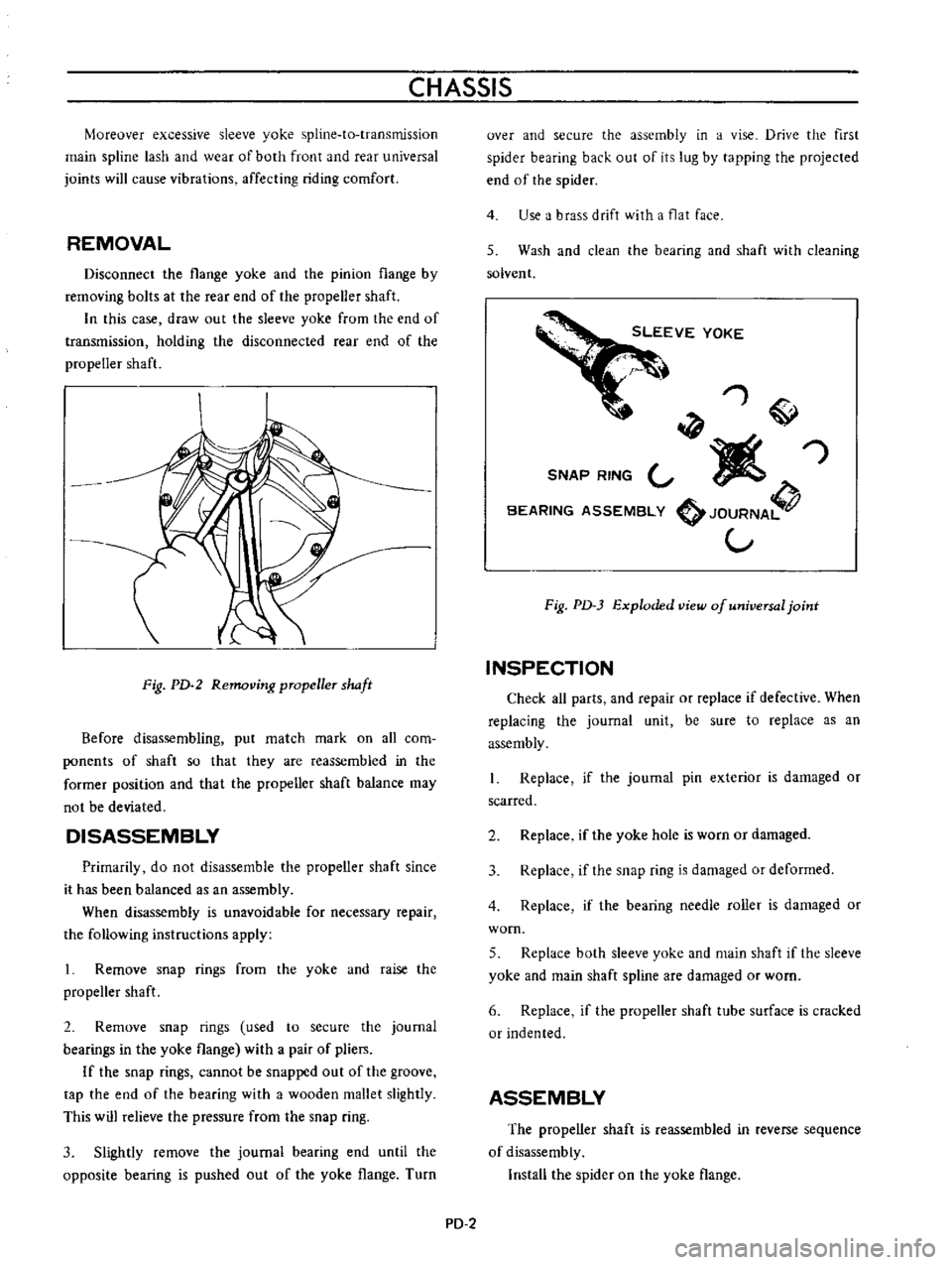
Fig
PD
l
Propeller
shaft
DESCRIPTION
Propeller
shaft
adopts
solid
tubular
steel
construction
A
correct
balance
of
propeller
shaft
is
very
important
for
a
good
riding
comfort
at
high
speed
Therefore
the
propeller
shafts
in
service
parts
and
ones
assembled
in
the
vehicle
are
counterbalanced
within
an
unbalance
of
IS
gr
cm
0
2
in
oz
at
4
000
rpm
at
the
factory
with
the
best
care
The
propeller
shaft
will
be
unbalanced
if
erroneously
tapped
with
a
hammer
while
servicing
or
flying
rocks
or
bottoming
during
off
road
driving
occurs
PD
1
Page 69 of 513

CHASSIS
Mureover
excessive
sleeve
yoke
spline
ta
transmission
main
spline
lash
and
wear
of
both
front
and
rear
universal
joints
will
cause
vibrations
affecting
riding
comfort
REMOVAL
Disconnect
the
flange
yoke
and
the
pinion
flange
by
removing
bolts
at
the
rear
end
of
the
propeller
shaft
In
this
case
draw
out
the
sleeve
yoke
from
the
end
of
transmission
holding
the
disconnected
rear
end
of
the
propeller
shaft
Fig
PD
2
Removing
pmpeller
shaft
Before
disassembling
put
match
mark
on
all
com
ponents
of
shaft
so
that
they
are
reassembled
in
the
former
position
and
that
the
propeller
shaft
balance
may
not
be
deviated
DISASSEMBLY
Primarily
do
not
disassemble
the
propeller
shaft
since
it
has
been
balanced
as
an
assembly
When
disassembly
is
unavoidable
for
necessary
repair
the
following
instructions
apply
1
Remove
snap
rings
from
the
yoke
and
raise
the
propeller
shaft
2
Remove
snap
rings
used
to
secure
the
journal
bearings
in
the
yoke
flange
with
a
pair
of
pliers
If
the
snap
rings
cannot
be
snapped
out
of
the
groove
tap
the
end
of
the
bearing
with
a
wooden
mallet
slightly
This
will
relieve
the
pressure
from
the
snap
ring
3
Slightly
remove
the
journal
bearing
end
until
the
opposite
bearing
is
pushed
out
of
the
yoke
flange
Turn
over
and
secure
the
assembly
in
a
vise
Drive
the
first
spider
bearing
back
out
of
its
lug
by
tapping
the
projected
end
of
the
spider
4
Use
a
brass
drift
with
a
flat
face
5
Wash
and
clean
the
bearing
and
shaft
with
cleaning
solvent
1
W
SNAP
RING
V
I
1Iiff
BEARING
ASSEMBLY
JOURNA
V
Fig
PD
3
Exploded
view
of
universal
joint
INSPECTION
Check
all
parts
and
repair
or
replace
if
defective
When
replacing
the
journal
unit
be
sure
to
replace
as
an
assembly
Replace
if
the
journal
pin
exterior
is
damaged
or
scarred
2
Replace
if
the
yoke
hole
is
worn
or
damaged
3
Replace
if
the
snap
ring
is
damaged
or
deformed
4
Replace
if
the
bearing
needle
roller
is
damaged
or
worn
5
Replace
both
sleeve
yoke
and
main
shaft
if
the
sleeve
yoke
and
main
shaft
spline
are
damaged
or
worn
6
Replace
if
the
propeller
shaft
tube
surface
is
cracked
or
Indented
ASSEMBLY
The
propeller
shaft
is
reassembled
in
reverse
sequence
of
disassembly
Install
the
spider
on
the
yoke
flange
PD
2
Page 70 of 513

PROPELLER
SHAFT
DIFFERENTIAL
CARRIER
Insert
the
journal
into
the
yoke
flange
Tap
the
journal
bearing
into
the
yoke
flange
using
a
brass
drift
smaller
than
the
hole
in
the
yoke
Tap
the
other
bearing
into
the
opposite
end
of
the
yoke
flange
until
the
bearing
is
in
line
with
the
snap
ring
grooves
With
a
pair
of
pliers
install
the
snap
rings
on
both
ends
of
the
yoke
flange
Insert
the
flange
assembly
in
the
sleeve
yoke
Place
the
other
yoke
bearing
into
the
opposite
end
of
the
yoke
and
tap
this
bearing
into
the
yoke
until
the
bearing
is
in
line
with
the
snap
ring
grooves
Install
the
snap
rings
on
both
ends
of
the
yoke
When
all
parts
are
assembled
check
the
spider
and
surroundings
for
tightness
When
the
clearance
is
excessive
adjust
with
over
size
snap
rings
as
follows
Snap
ring
over
size
Thickness
Color
mrn
in
identification
I
46
0
0575
White
I
48
0
0583
Yellow
1
50
0
0591
Red
1
52
0
0598
Green
1
54
0
0606
Blue
1
56
0
0614
1
58
0
0622
SERVICE
DATA
AND
SPECIFICATIONS
Distance
between
joints
mm
in
Tube
outer
diameter
x
thickness
mm
in
Sleeve
yoke
specification
Outer
dia
x
inner
dia
x
pitch
mm
in
Brown
No
mark
I
189
46
8
68
9
x
1
6
2
713
x
0
0630
Involute
spline
20
x
80
x
I
0
787
x
3
150
x
0
0394
Permissible
unbalance
gr
cm
in
oz
rpm
15
0
2
4
000
Allowable
max
swinging
torque
of
spider
journal
10
9
kg
cm
in
lb
Propeller
shaft
run
out
mm
in
Tightening
torque
of
companion
flange
nuts
kg
m
ft
Ib
TROUBLE
DIAGNOSES
AND
CORRECTIONS
Condition
Probable
cause
Noise
and
vibration
Distorted
propeller
shaft
Unbalanced
propeller
shaft
Corrective
action
less
than
0
6
0
024
2
0
to
2
7
I4
to
20
Using
exclusively
an
arbor
press
restraighten
If
distortion
is
excessive
replace
propeller
shaft
Check
for
balance
If
unbalance
exceeds
the
limit
replace
it
Recorrect
Replace
the
sleeve
yoke
Replace
the
journal
Replace
with
correct
snap
ring
Retighten
nuts
to
the
specified
torque
Incorrectly
positioned
flange
yoke
Excessive
spline
lash
Worn
or
damaged
journal
Inconect
snap
rings
Loose
nuts
securing
the
flange
yoke
to
the
companion
flange
PD
3
Page 71 of 513

CHASSIS
DIFFERENTIAL
CARRIER
CONTENTS
DESCRIPTION
REMOVAL
DISASSEMBL
Y
INSPECTION
AND
REPAIR
ASSEMBLY
AND
ADJUSTMENT
Assembling
differential
gear
case
Setting
and
adjusting
drive
pinion
PD
4
PD
5
PD
5
PD
7
PD
8
PD
9
PD
10
Adjusting
drive
pinion
preload
Setting
and
adjusting
side
bearing
shims
INSTALLATION
TROUBLE
DIAGNOSES
AND
CORRECTIONS
SERVICE
DATA
AND
SPECIFICATIONS
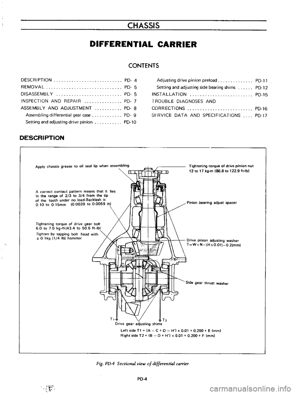
DESCRIPTION
Apply
chassis
grease
to
oil
seal
lip
when
assembling
Tightening
torque
of
drive
pinion
nut
12
to
17
kg
m
86
8
to
122
9
ft
Ib
A
correct
contact
pattern
means
that
it
lies
in
the
range
of
213
to
3
4
from
the
tip
of
the
tooth
under
no
load
Backlash
is
O
10
to
0
15mm
10
0039
to
0
0059
in
Pinion
bearing
adjust
spacer
Tightening
torque
of
drive
gear
bolt
6
0
to
7
0
kg
m
43
4
to
50
6
ft
Ibl
Tighten
by
tapping
bolt
head
with
a
0
1
kg
1
4
Ib
hammer
Drive
pinion
adjusting
washer
T
W
N
IH
xO
OlJ
O
21mml
Side
gear
thrust
washer
Left
side
T1
A
C
0
H
j
x
0
01
0
200
E
mm
Right
side
T2
B
0
H
0
01
0
200
F
mm
Fig
PD
4
Sectional
view
of
differential
carrier
PD
4
Y
I
PD
l1
PD
12
PD
15
PD
16
PD
17
Page 72 of 513

PROPELLER
SHAFT
DIFFERENTIAL
CARRIER
The
gear
carrier
is
made
of
light
and
strong
aluminum
alloy
metal
and
hypoid
bevel
gear
is
used
Adjust
drive
pinion
bearing
preload
with
non
adjusting
type
spacer
and
pinion
height
and
side
bearing
adjust
ment
with
spacer
shim
s
Millimeter
standardization
stilI
remains
for
all
the
screw
threads
of
this
unit
Therefore
adjustment
figures
stamped
on
screws
adjusting
shims
washers
differential
case
drive
pinion
and
carrier
are
in
millimeters
in
accordance
with
the
millimeter
standardization
of
parts
The
proper
lubrication
to
the
gear
housing
is
necessary
otherwise
it
would
shorten
the
durability
of
the
gear
and
cause
other
troubles
The
lubricant
should
be
checked
each
5
000
km
3
000
miles
and
replenished
each
50
000
km
30
000
miles
The
lubricant
should
be
drained
and
ref11led
at
the
end
of
the
first
1
000
km
600
miles
to
eliminate
any
loose
material
from
the
sump
which
results
from
breaking
Differential
lubricant
should
be
changed
at
least
every
50
000
km
30
000
miles
ConsIderations
should
be
given
to
the
following
matters
I
Nominated
hypoid
gear
oil
must
be
used
2
It
is
prohibited
to
use
any
gear
oil
of
different
viscosity
The
same
brand
must
always
be
selected
3
The
standard
oil
capacity
is
about
0
75
liter
0
198
US
gal
REMOVAL
Fig
PD
5
Removing
differential
gear
carrier
To
remove
the
gear
carrier
assembly
disconnect
the
drive
pinion
companion
flange
te
flange
yoke
connection
and
remove
two
rear
axle
shafts
Refer
to
REAR
AXLE
for
the
work
DISASSEMBLY
I
Install
the
gear
carrier
assembly
on
the
Gear
Carrier
Attachment
ST06320000
ST06320000
Fig
PD
6
Holding
differential
camer
2
Inspect
the
following
before
disassembling
I
Inspect
the
tooth
contact
pattern
with
a
lead
oxide
2
Measure
backlash
between
drive
gear
and
pinion
gear
using
a
dial
indicator
3
Put
match
mark
on
one
side
of
the
side
bearing
cap
by
the
use
of
a
punch
SIDCBEMING
c
e
Fig
PD
7
Putting
mark
PD
5