Page 433 of 513

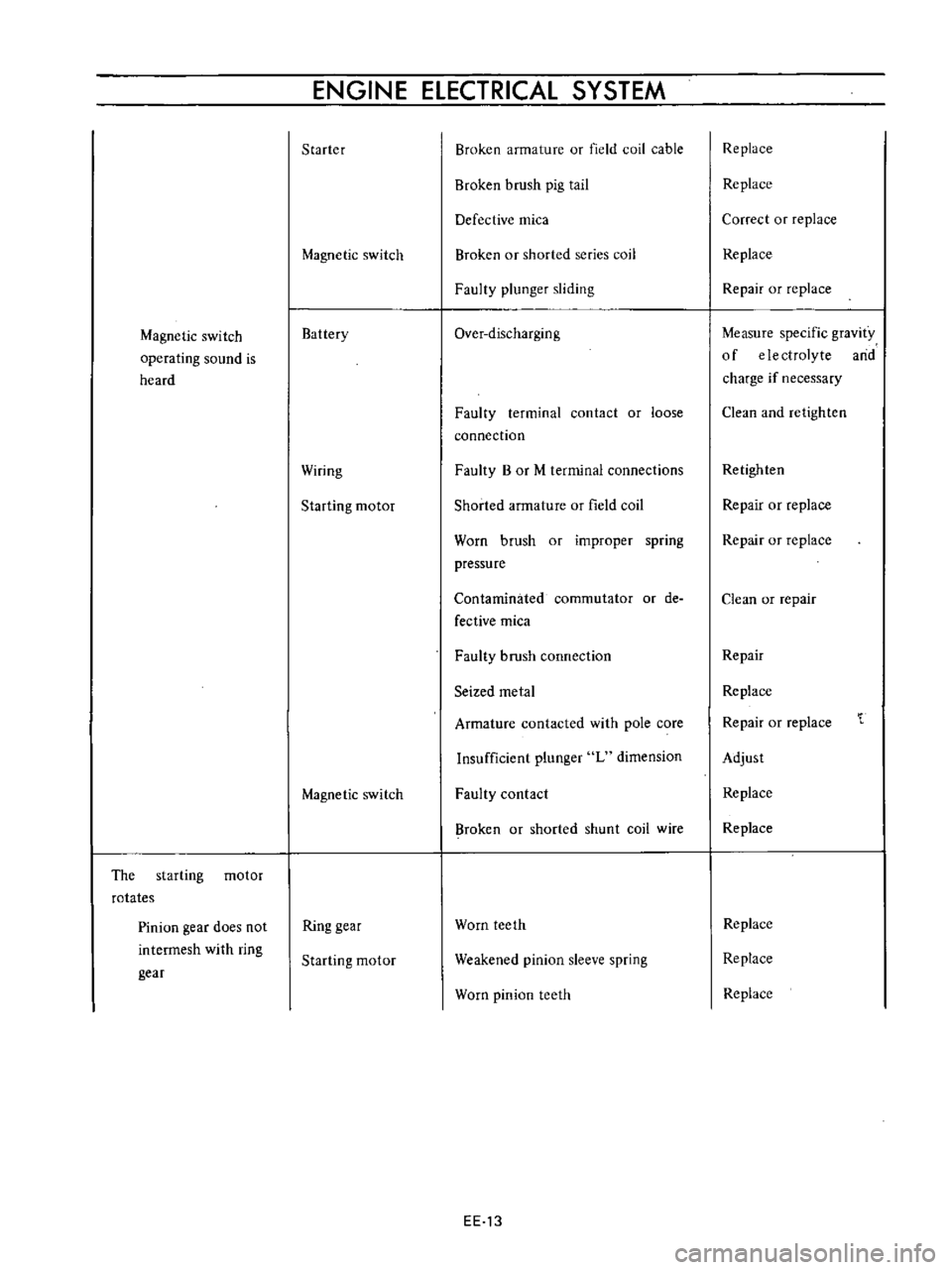
Magnetic
switch
operating
sound
is
heard
The
starting
motor
rotates
Pinion
gear
does
not
intermesh
with
ring
gear
ENGINE
ELECTRICAL
SYSTEM
Starter
Magnetic
switch
Battery
Wiring
Starting
motor
Magnetic
switch
Ring
gear
Starting
motor
Broken
armature
or
field
coil
cable
Broken
brush
pig
tail
Defective
mica
Broken
or
shorted
series
coil
Faulty
plunger
sliding
Over
discharging
Faulty
terminal
contact
or
loose
connection
Faulty
B
or
M
terminal
connections
Shorted
armature
or
field
coil
Worn
brush
or
improper
spring
pressure
Contaminated
commutator
or
de
fective
mica
Faulty
brush
connection
Seized
metal
Armature
contacted
with
pole
core
Insufficient
plunger
L
dimension
Faulty
contact
Broken
or
shorted
shunt
coil
wire
Worn
teeth
Weakened
pinion
sleeve
spring
Worn
pinion
teeth
EE
13
Replace
Replace
Correct
or
replace
Replace
Repair
or
replace
Measure
specific
gravity
of
electrolyte
arid
charge
if
necessary
Clean
and
retighten
Retighten
Repair
or
replace
Repair
or
replace
Clean
or
repair
Repair
Replace
Repair
or
replace
Adjust
Replace
Replace
Replace
Replace
Replace
Page 434 of 513

Pinion
intermeshes
with
ring
gear
Starting
motor
rotates
and
pinion
intermeshes
with
ring
gear
but
ro
tation
is
too
slow
When
starting
switch
is
set
to
OFF
the
start
ing
motor
does
not
stop
Starting
motor
Battery
Wiring
Ignition
switch
Starting
motor
Ignition
switch
Magnetic
switch
Starting
motor
ENGINE
Faulty
pinion
sliding
Dropped
off
lever
pin
Excessive
plunger
L
dimension
Defective
over
running
clutch
Over
discharging
Improper
or
loose
terminal
contact
Improperly
tightened
connection
Rough
contact
surface
Shorted
armature
coil
or
field
coil
Worn
brush
or
insufficient
spring
pressure
Contaminated
commutator
or
im
proper
brush
contact
Defective
mica
Lack
of
metal
lubrication
Armature
contacted
with
pole
core
Faulty
returning
Seized
contact
Shorted
coil
Faulty
plunger
sliding
Pinion
does
not
disengage
from
the
ring
gear
smoothly
Pinion
spline
does
not
disengage
smoothly
Seized
pinion
metal
EE
14
Repair
Repair
Adjust
Replace
Charge
battery
Repair
and
retighten
Retighten
Repair
or
replace
Repair
or
replace
Repair
or
replace
Repair
Repair
Repair
or
replace
Repair
or
replace
Replace
Replace
Replace
Replace
Repair
or
replace
Repair
or
replace
Replace
Page 435 of 513

ENGINE
ElECTRICAL
SYSTEM
CHARGING
CIRCUIT
IGNITION
1
i
n
ITCH
r
B
i
i
vel
oU
ARMATURE
lip
J
l
t
lJ
FIEL
Df
e
I
I
3
2
I
u
P
5
0
IL
U
p
P
f
H
i
I
I
L
J
L
J
ALTERNATOR
VOL
TAGE
REGULATOR
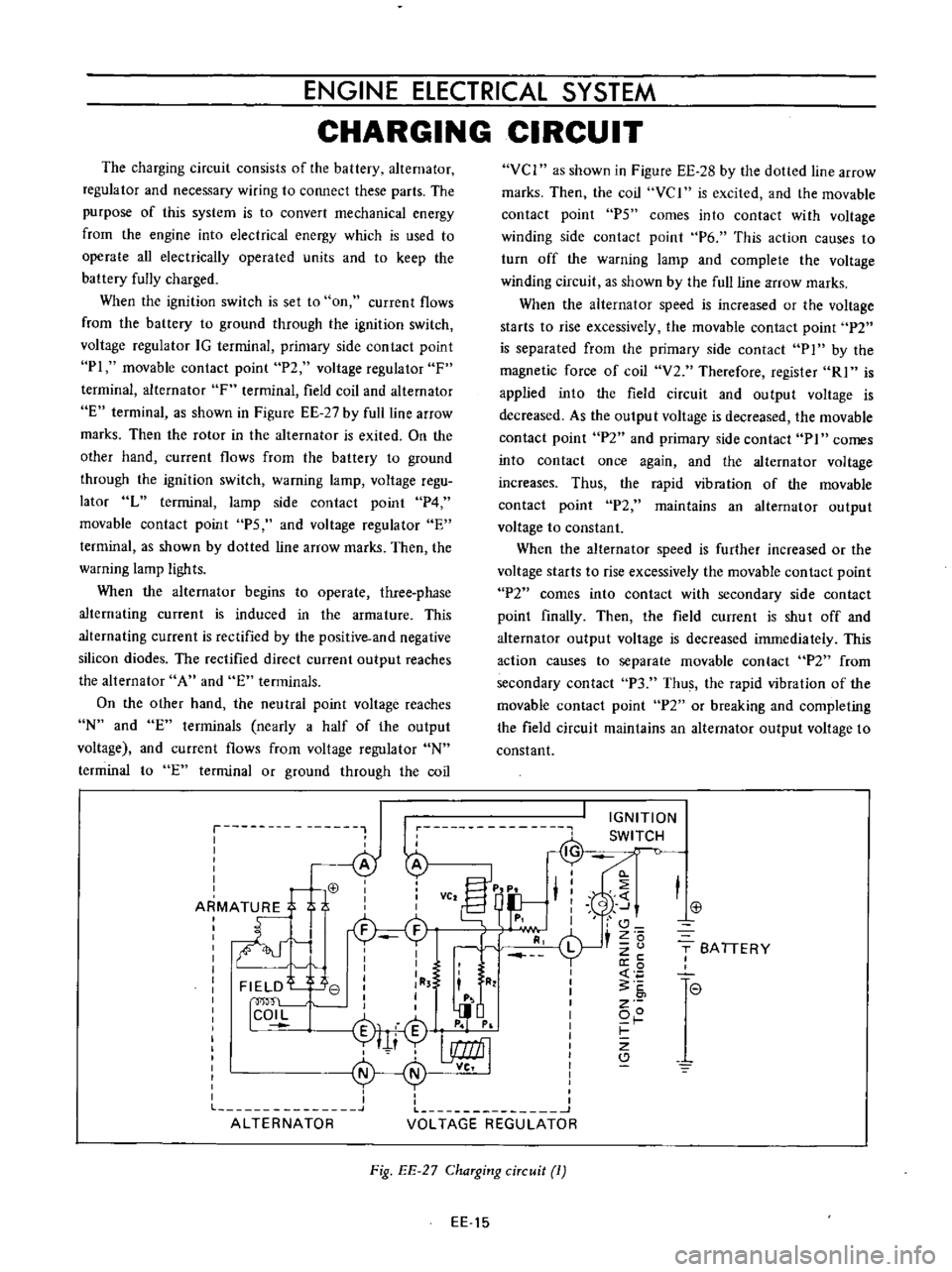
The
charging
circuit
consists
of
the
battery
alternator
regulator
and
necessary
wiring
to
connect
these
parts
The
purpose
of
this
system
is
to
convert
mechanical
energy
from
the
engine
into
electrical
energy
which
is
used
to
operate
all
electrically
operated
units
and
to
keep
the
battery
fully
charged
When
the
ignition
switch
is
set
to
on
current
flows
from
the
battery
to
ground
through
the
ignition
switch
voltage
regulator
IG
terminal
primary
side
contact
point
PI
movable
contact
point
P2
voltage
regulator
F
terminal
alternator
F
terminal
field
coil
and
alternator
E
terminal
as
shown
in
Figure
EE
27
by
full
line
arrow
marks
Then
the
rotor
in
the
alternator
is
exited
On
the
other
hand
current
flows
from
the
battery
to
ground
through
the
ignition
switch
warning
lamp
voltage
regu
lator
L
terminal
lamp
side
contact
point
P4
movable
contact
point
PS
and
voltage
regulator
E
terminal
as
shown
by
dotted
line
arrow
marks
Then
the
warning
lamp
ligh
ts
When
the
alternator
begins
to
operate
three
phase
alternating
current
is
induced
in
the
armature
This
alternating
current
is
rectified
by
the
positive
and
negative
silicon
diodes
The
rectified
direct
current
output
reaches
the
alternator
A
and
E
terminals
On
the
other
hand
the
neutral
point
voltage
reaches
N
and
E
terminals
nearly
a
half
of
the
output
voltage
and
current
flows
from
voltage
regulator
N
terminal
to
E
terminal
or
ground
through
the
coil
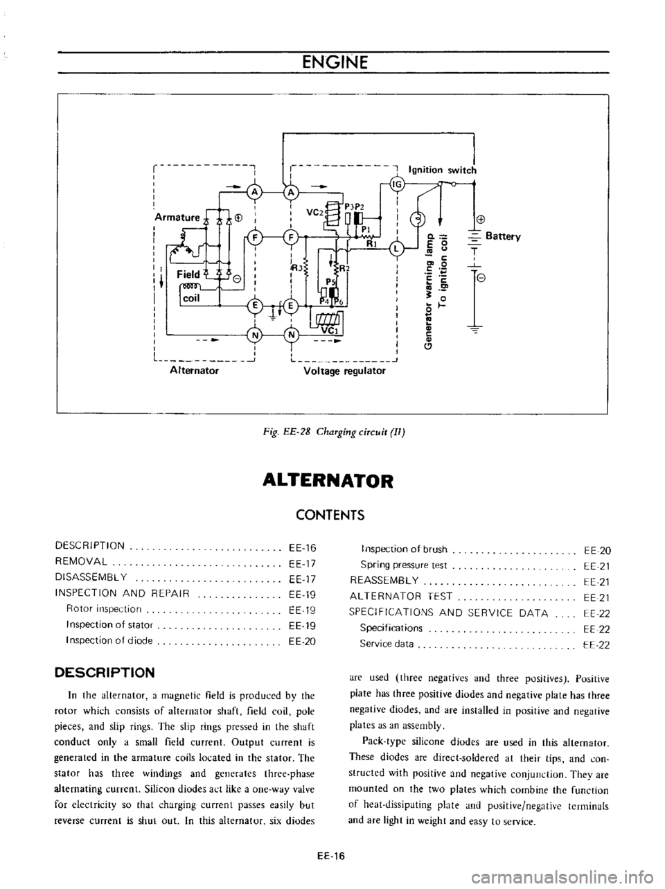
VCI
as
shown
in
Figure
EE
28
by
the
dolled
line
arrow
marks
Then
the
coil
vc
I
is
excited
and
the
movable
contact
point
P5
comes
into
contact
with
voltage
winding
side
contact
point
P6
This
action
causes
to
turn
off
the
warning
lamp
and
complete
the
voltage
winding
circuit
as
shown
by
the
ullline
arrow
marks
When
the
alternator
speed
is
increased
or
the
voltage
starts
to
rise
excessively
the
movable
contact
point
P2
is
separated
from
the
primary
side
contact
P
1
by
the
magnetic
force
of
coil
V2
Therefore
register
RI
is
applied
into
the
field
circuit
and
output
voltage
is
decreased
As
the
outpu
t
voltage
is
decreased
the
movable
contact
point
P2
and
primary
side
contact
PI
comes
into
contact
once
again
and
the
alternator
voltage
increases
Thus
the
rapid
vibration
of
the
movable
contact
point
P2
maintains
an
alternator
output
voltage
to
constant
When
the
alternator
speed
is
further
increased
or
the
voltage
starts
to
rise
excessively
the
movable
contact
point
P2
comes
into
contact
with
secondary
side
contact
point
finally
Then
the
field
current
is
shut
off
and
alternator
output
voltage
is
decreased
immediately
This
action
causes
to
separate
movable
contact
P2
from
secondary
contact
P3
Thus
the
rapid
vibration
of
the
movable
contact
point
P2
or
breaking
and
completing
the
field
circuit
maintains
an
alternator
output
voltage
to
constant
j
T
SA
TIERY
I
l
e
7
Fig
EE
27
ChaTging
ciTcuit
1
EE
15
Page 436 of 513

ENGINE
r
Ignition
switJ
c
o
iArm
ture
j
i
i
VC2
P
tP2
d
I
I
I
PI
I
ll
Rl
L
I
I
lRJ
t
R
I
Field
e
I
I
I
I
Ps
I
1
I
I
n
I
coil
M
4
i
f
I
L
1
J
Alternator
Voltage
regulator
Fig
EE
2B
ChaTging
ciTcuit
II
ALTERNATOR
CONTENTS
DESCRIPTION
REMOVAL
DISASSEMBL
Y
INSPECTION
AND
REPAIR
Rotor
inspection
Inspection
of
stator
I
nspection
of
diode
EE
16
EE
17
EE
17
EE
19
EE
19
EE
19
EE
20
DESCRIPTION
In
the
alternator
a
magnetic
field
is
produced
by
the
rotor
which
consists
of
alternator
shaft
field
coil
pole
pieces
and
slip
rings
The
slip
rings
pressed
in
the
shaft
conduct
only
a
small
field
current
Output
current
is
generated
in
the
armature
coils
located
in
the
stator
The
stator
has
three
windings
and
generates
three
phase
alternating
currenl
Silicon
diudes
act
like
a
one
way
valve
for
electricity
so
that
charging
currcnt
passes
easily
but
reverse
current
is
shut
out
In
this
alternator
six
diodes
0
E
0
c
co
0
E
c
o
0
c
Cl
Battery
T
e
I
nspection
of
brush
Spring
pressure
test
REASSEMBL
Y
ALTERNATOR
TEST
SPECIFICATIONS
AND
SERVICE
DATA
Specifications
Service
data
EE
20
EE
21
EE
21
EE
21
EE
22
EE
22
EE
22
are
used
three
negatives
and
three
positives
Positive
plate
has
three
positive
diodes
and
negative
plate
has
three
negative
diodes
and
are
installed
in
positive
and
negative
plates
as
an
assembly
Pack
type
silicone
diodes
are
used
in
this
alternator
These
diodes
are
direct
soldered
at
their
tips
and
con
structed
with
positive
and
negative
conjunction
They
are
mounted
on
the
two
plates
which
combine
the
function
of
heat
dissipating
plate
and
positive
negative
terminals
and
are
light
in
weight
and
easy
to
service
EE
16
Page 437 of 513
ENGINE
ElECTRICAL
SYSTEM
CD
@
@
@
y
@
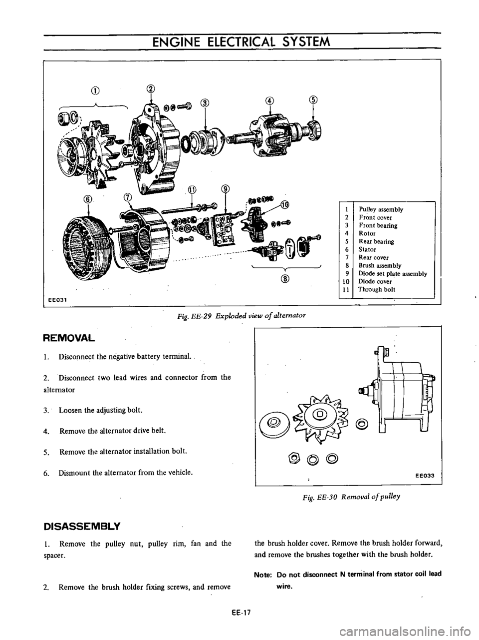
1
Pulley
assembly
2
Front
cover
3
Front
bearing
4
Rotor
5
Rear
bearing
6
Stator
7
Rear
cover
8
Brush
assembly
9
Diode
set
pl
te
assembly
10
Diode
cover
Jl
Through
bolt
EE031
Fig
EE
29
Exploded
view
of
altematoT
REMOVAL
3
Loosen
the
adjusting
bolt
@
o
lL
1
Disconnect
the
negative
battery
terminal
2
Disconnect
two
lead
wires
and
connector
from
the
alternator
4
Remove
the
alternator
drive
belt
@
J
5
Remove
the
alternator
installation
bolt
@@@
6
Dismount
the
alternator
from
the
vehicle
EE033
Fig
EE
JO
Removal
of
pulley
DISASSEMBLY
l
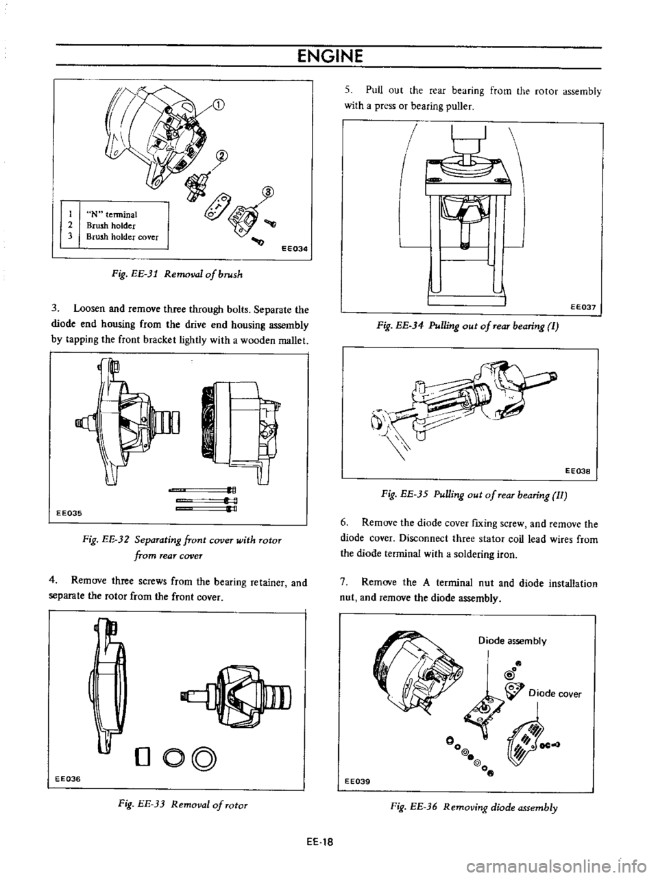
Remove
the
pulley
nut
pulley
rim
fan
and
the
spacer
the
brush
holder
cover
Remove
the
brush
holder
forward
and
remove
the
brushes
together
with
the
brush
holder
2
Remove
the
brush
holder
fixing
screws
and
remove
Note
Do
not
disconnect
N
term
inal
from
stator
coil
lead
wire
EE
17
Page 438 of 513

ENGINE
G
2
3
N
terminal
Brush
holder
Brush
holder
cover
@
f
fI
0
EE034
Fig
EE
31
Removal
of
brush
3
Loosen
and
remove
three
through
bolts
Separate
the
diode
end
housing
from
the
drive
end
housing
assembly
by
tapping
the
front
bracket
lightly
with
a
wooden
mallet
1
L
c
EE035
Fig
EE
32
Separating
front
cover
with
Totor
from
rear
cover
4
Remove
three
screws
from
the
bearing
retainer
and
separate
the
rotor
from
the
front
cover
L1
1
t
DO
L
EE036
Fig
EE
33
Removal
of
TOtOT
5
Pull
out
the
rear
bearing
from
the
rotor
assembly
with
a
press
or
bearing
puller
I
I
l
I
EE037
Fig
EE
34
Pulling
out
of
TeaT
bearing
I
j
EE038
Fig
EE
35
Pulling
out
of
Tear
bearing
II
6
Remove
the
diode
cover
fIxing
screw
and
remove
the
diode
cover
Disconnect
three
stator
coil
lead
wires
from
the
diode
terminal
with
a
soldering
iron
7
Remove
the
A
terminal
nut
and
diode
installation
nut
and
remove
the
diode
assembly
Diode
assembly
I
o
@
Diode
cover
rJ
0
00
@
Y
o@
o
EE039
Fig
EE
36
Removing
diode
assembly
EE
18
Page 439 of 513

ENGINE
ELECTRICAL
SYSTEM
Note
Use
care
in
handling
diode
assembly
to
prevent
an
undue
stress
on
it
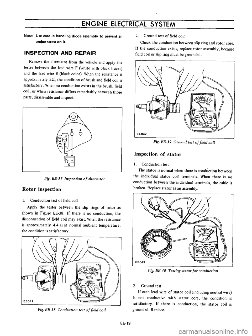
INSPECTION
AND
REPAIR
Remove
the
alternator
from
the
vehicle
and
apply
the
tester
between
the
lead
wire
F
white
with
black
tracer
and
the
lead
wire
E
black
color
When
the
resistance
is
approximately
511
the
condition
of
brush
and
field
coil
is
satisfactory
When
no
conduction
exists
in
the
brush
field
coil
or
when
resistance
differs
remarkably
between
those
parts
disassemble
and
inspect
E
o
Fig
BE
37
Inspection
of
alternator
Rotor
inspection
I
Conduction
test
of
field
coil
Apply
the
tester
between
the
slip
rings
of
rotor
as
shown
in
Figure
EE
38
If
there
is
no
conduction
the
disconnection
of
field
coil
may
exist
When
the
resistance
is
approximately
4
4
n
at
normal
ambient
temperature
the
condition
is
satisfactory
Fig
EE
3B
Conduction
test
of
field
coil
2
Ground
test
of
field
coil
Check
the
conduction
between
slip
ring
and
rotor
core
If
the
conduction
exists
replace
rotor
assembly
because
field
coil
or
slip
ring
must
be
grounded
EE042
Fig
EE
39
GTound
test
of
field
coil
Inspection
of
stator
1
Conduction
test
The
stator
is
normal
when
there
is
conduction
between
the
individual
stator
coil
terminals
When
there
is
no
conduction
between
the
individual
terminals
the
cable
is
broken
Replace
stator
as
an
assembly
EE043
Fig
EE
40
Testing
stator
for
cmlduction
2
Ground
test
If
each
lead
wire
of
stator
coil
including
neutral
wire
is
not
conductive
with
stator
core
the
condition
is
satisfactory
If
there
is
conduction
the
stator
coil
is
grounded
Replace
EE
19
Page 440 of 513

ENGINE
Stator
core
EE044
Fig
EE
41
Testing
stator
for
ground
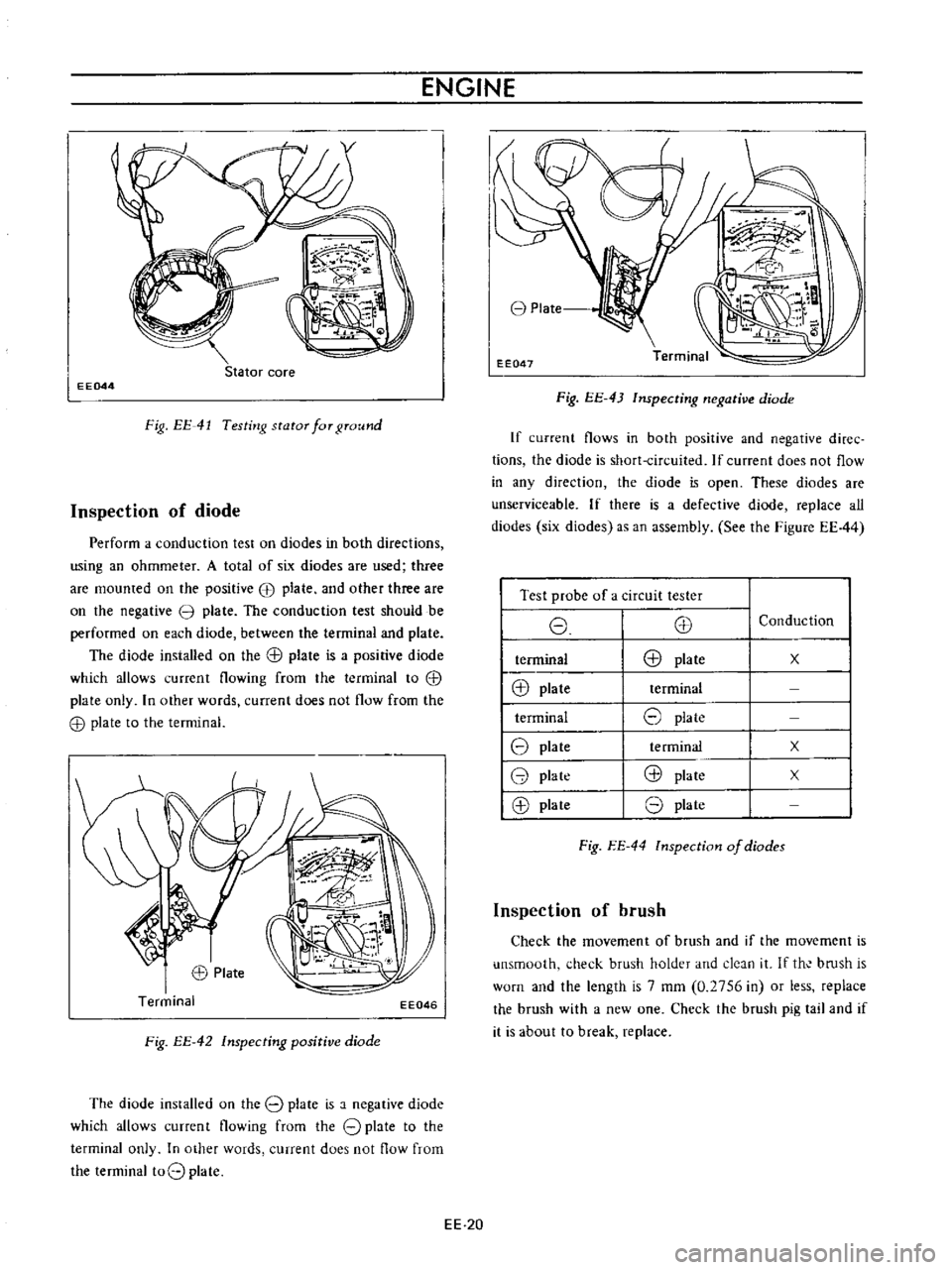
Inspection
of
diode
Perform
a
conduction
test
on
diodes
in
both
directions
using
an
ohmmeter
A
total
of
six
diodes
are
used
three
are
mounted
on
the
positive
EB
plate
and
other
three
are
on
the
negative
3
plate
The
conduction
test
should
be
performed
on
each
diode
between
the
terminal
and
plate
The
diode
installed
on
the
G
l
plate
is
a
positive
diode
which
allows
current
flowing
from
the
terminal
to
G
l
plate
only
In
other
words
current
does
not
flow
from
the
G
l
plate
to
the
terminal
EE046
Fig
EE
42
Inspecting
positive
diode
The
diode
installed
on
the
8
plate
is
a
negative
diode
which
allows
current
flowing
from
the
8
plate
to
the
terminal
only
In
other
words
current
does
not
flow
from
the
terminal
t08
plate
EE
20
8
Plate
EE047
Fig
EE
43
Inspecting
negative
diode
If
current
flows
in
both
positive
and
negative
diree
tions
the
diode
is
short
circuited
If
current
does
not
flow
in
any
direction
the
diode
is
open
These
diodes
are
unserviceable
If
there
is
a
defective
diode
replace
all
diodes
six
diodes
as
an
assembly
See
the
Figure
EE44
I
Test
probe
of
a
circuit
tester
I
8
E8
I
terminal
E8
plate
I
@
plate
terminal
I
terminal
8
plate
18
plate
te
rminal
18
plate
@
plate
18
plate
8
plate
Conduction
x
x
x
Fig
EE
44
lnspection
of
diodes
Inspection
of
brush
Check
the
movement
of
brush
and
if
the
movement
is
unsmooth
check
brush
holder
and
deJn
it
If
th
bmsh
is
worn
and
the
length
is
7
mm
0
2756
in
or
less
replace
the
brush
with
a
new
one
Check
the
brush
pig
tail
and
if
it
is
about
to
break
replace