Page 249 of 513

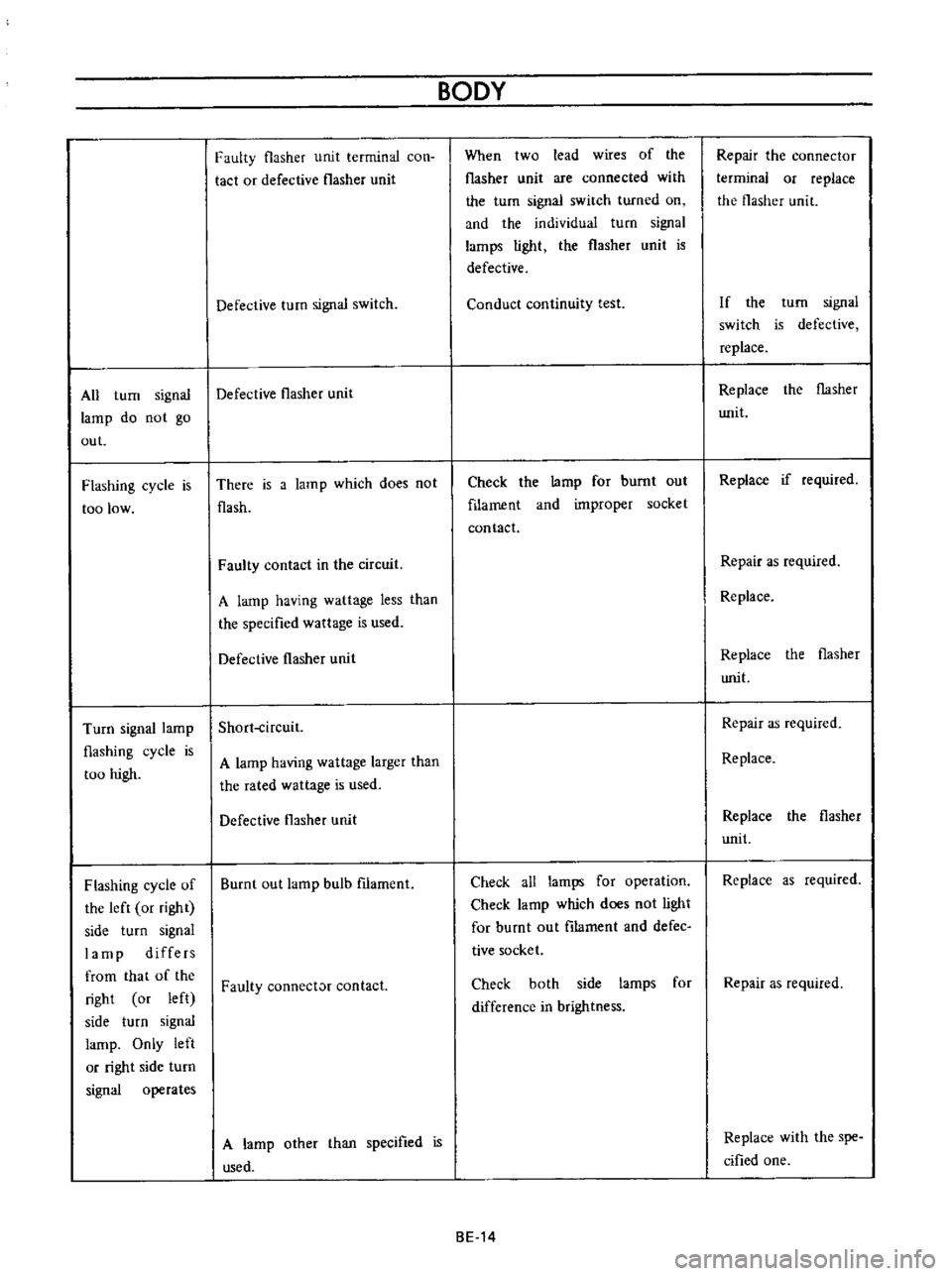
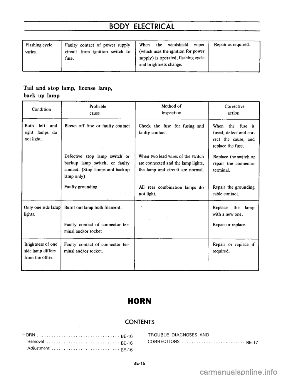
All
turn
signal
lamp
do
not
go
out
Flashing
cycle
is
too
low
Turn
signal
lamp
flashing
cycle
is
too
high
Flashing
cycle
of
the
left
or
right
side
turn
signal
lamp
differs
from
that
of
the
right
or
left
side
turn
signal
lamp
Only
left
or
right
side
turn
signal
operates
Faulty
flasher
unit
terminal
con
tact
or
defective
flasher
unit
Defective
turn
signal
switch
Defective
flasher
unit
There
is
a
lam
p
which
does
no
t
flash
Faulty
contact
in
the
circuit
A
lamp
having
wattage
less
than
the
specified
wattage
is
used
Defective
flasher
unit
Short
ircuit
A
lamp
having
wattage
larger
than
the
rated
wattage
is
used
Defective
flasher
unit
Burnt
out
lamp
bulb
filament
Faulty
connect
contact
A
lamp
other
than
specified
is
used
BODY
When
two
lead
wires
of
the
flasher
unit
are
connected
with
the
turn
signal
switch
turned
on
and
the
individual
turn
signal
larnps
light
the
flasher
unit
is
defective
Conduct
continuity
test
Check
the
lamp
for
burnt
out
filament
and
improper
socket
contact
Check
all
lamps
for
operation
Check
lamp
which
does
not
light
for
burnt
out
filarnent
and
defec
tive
socket
Check
both
side
larnps
for
difference
in
brightness
BE
14
Repair
the
connector
terminal
or
replace
the
flasher
unit
If
the
turn
signal
switch
is
defective
replace
Replace
the
flasher
Wlit
Replace
if
required
Repair
as
required
Replace
Replace
the
flasher
writ
Repair
as
required
Replace
Replace
the
flasher
unit
Replace
as
required
Repair
as
required
Replace
with
the
spe
cified
one
Page 250 of 513

Flashing
cycle
varies
BODY
ELECTRICAL
Faulty
contact
of
power
supply
circuit
from
ignition
switch
to
fuse
Tail
and
stop
lamp
license
lamp
back
up
lamp
Condition
Both
left
and
right
lamps
do
not
light
Probable
cause
Blown
off
fuse
or
faulty
contact
Defective
stop
larnp
switch
or
backup
lamp
switch
or
faulty
contact
Stop
larnps
and
backup
lamp
only
Faulty
grounding
Only
one
side
lamp
Burnt
out
lamp
bulb
f1lament
lights
Brightness
of
one
side
lamp
differs
from
the
other
HORN
Removal
Adjustment
Faulty
contact
of
connector
ter
minal
and
or
socket
Faulty
contact
of
connector
ter
minal
and
or
socket
BE
16
BE
16
BE
16
When
the
windshield
wiper
which
uses
the
ignition
for
power
supply
is
operated
flashing
cycle
and
brightness
change
Method
of
inspection
Check
the
fuse
for
fusing
and
faulty
contact
When
two
lead
wires
of
the
switch
are
connected
and
the
lamp
lights
the
larnp
and
circuit
are
normal
All
rear
combination
lamps
do
not
light
HORN
CONTENTS
TROUBLE
DIAGNOSES
AND
CORRECTIONS
BE
15
Repair
as
required
Corrective
action
When
the
fuse
is
fused
detect
and
COf
rect
the
cause
and
replace
the
fuse
Replace
the
switch
or
repair
the
connector
terrninal
Repair
the
grounding
cable
contact
Replace
the
larnp
with
a
new
one
Repair
or
replace
Repair
or
replace
if
required
BE
17
Page 251 of 513

9HORN
r
I
01
8ATTERY
HI
IGI
s
ILl
C
iORN
BODY
FUSE
H
S
HORN
BUTTON
BGI
J
H
B
S
Il
I
n6lm
I
L
J
L
HORN
RELAY
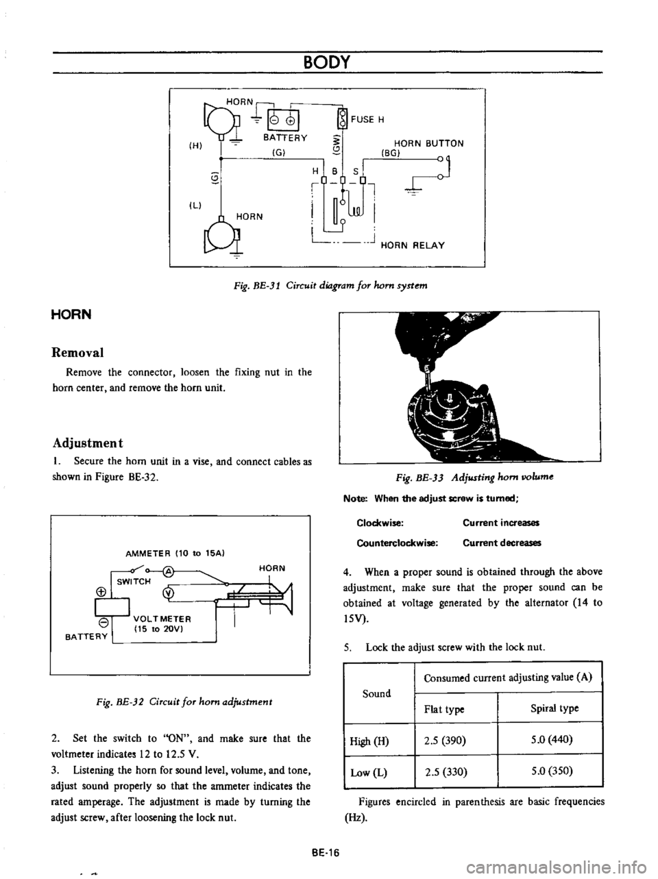
Fig
BE
3l
Circuit
diagram
for
hom
syrtem
HORN
Removal
Remove
the
connector
loosen
the
fixing
nut
in
the
horn
center
and
remove
the
horn
unit
Adjustment
1
Secure
the
horn
unit
in
a
vise
and
connect
cables
as
shown
in
Pigure
BE
32
AMMETER
110
to
15AI
Isw
f
@
113
I
VOLTMETER
I
15
to
20VI
BATTERY
HORN
Fig
BE
32
Circuit
for
ham
adjustment
2
Set
the
switch
to
ON
and
rnake
sure
that
the
voltmeter
indicates
12
to
12
5
V
3
Listening
the
horn
for
sound
level
volurne
and
tone
adjust
sound
properly
so
that
the
amrneter
indicates
the
rated
amperage
The
adjustment
is
made
by
turning
the
adjust
screw
after
loosening
the
lock
nut
Fig
BE
33
Adjusting
hom
IIOlume
Note
When
the
adjust
screw
is
turned
Clockwise
Counterclockwise
Current
increases
Current
decreases
4
When
a
proper
sound
is
obtained
through
the
above
adjustment
rnake
sure
that
the
proper
sound
can
be
obtained
at
voltage
generated
by
the
alternator
14
to
l5V
5
Lock
the
adjust
screw
with
the
lock
nut
Consumed
current
adjusting
value
A
Sound
Plat
type
Spiral
type
High
H
2
5
390
5
0
440
Low
L
2
5
330
5
0
350
Figures
encircled
in
parenthesis
are
basic
frequencies
Hz
BE
16
Page 252 of 513

BODY
ELECTRICAL
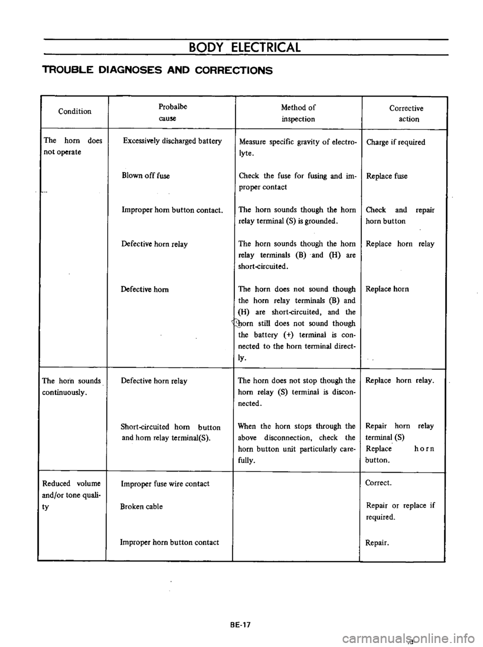
TROUBLE
DIAGNOSES
AND
CORRECTIONS
Condition
The
horn
does
not
operate
The
horn
sounds
continuously
Reduced
volume
and
or
tone
quali
ty
Probalbe
cause
Excessively
discharged
battery
Blown
off
fuse
Improper
horn
button
contact
Defective
horn
relay
Defective
horn
Defective
horn
relay
Short
circuited
horn
button
and
horn
relay
terminal
S
Improper
fuse
wire
contact
Broken
cable
Improper
horn
button
contact
Method
of
inspection
Measure
specific
gravity
of
electro
lyte
Corrective
action
Charge
if
required
Check
the
fuse
for
fusing
and
im
Replace
fuse
proper
contact
The
horn
sounds
though
the
horn
relay
terrninal
S
is
grounded
Check
and
repair
horn
button
The
horn
sounds
though
the
horn
Replace
horn
relay
relay
terrninals
B
and
H
are
short
circuited
The
horn
does
not
sound
though
Replace
horn
the
horn
relay
terminals
B
and
H
are
short
circuited
and
the
porn
still
does
not
sound
though
the
battery
terminal
is
con
nected
to
the
horn
terminal
direct
ly
The
horn
does
not
stop
though
the
Replace
horn
relay
horn
relay
S
terminal
is
discon
nected
When
the
horn
stops
through
the
above
disconnection
check
the
horn
button
unit
particularly
care
fully
BE
17
Repair
horn
relay
terminal
S
Replace
horn
button
Correct
Repair
or
replace
if
required
Repair
d
Page 253 of 513

BODY
METERS
AND
GAUGES
CONTENTS
CLUSTER
LID
Oescri
ption
Removal
SPEEDOMETER
Replacement
FUEL
GAUGE
AND
TEMPERATURE
GAUGE
Description
Replacement
BE
1B
BE
18
BE
18
BE
19
BE
19
BE
19
BE
19
BE
20
CLUSTER
LID
Description
The
cluster
lid
holds
various
rneters
indicators
and
clock
located
around
the
speedorneter
Printed
circuit
board
is
used
at
the
back
of
the
meter
as
shown
in
Figure
BE
38
and
the
printed
circuit
board
is
connected
with
multiple
connectors
Thus
the
meters
Can
be
inspected
and
serviced
extremely
easily
Except
for
the
speed
ometer
all
rneters
are
operated
electrically
The
fuel
gauge
and
therrnometer
are
very
reliable
and
they
are
equipped
with
bimetal
devices
F
a
o
ill
I
1
a
a
Fig
BE
34
Combination
meters
Removal
Disconnect
the
battery
terminal
depressing
the
OIL
PRESSURE
AND
IGNITION
WARNING
LAMPS
HAND
BRAKE
WARNING
LAMP
BULB
SPECIFICATIONS
TROUBLE
DIAGNOSES
AND
CORRECTIONS
Speedometer
Thermometer
and
fuel
meter
Oil
pressure
and
ignition
warning
lamps
BE
20
BE
21
BE
21
BE
22
BE
22
BE
23
BE
25
windshield
wiper
switch
lighting
switch
and
choke
lever
knobs
turn
them
counterclockwise
to
remove
Remove
the
escutcheon
2
Inserting
your
hand
into
back
of
the
cluster
lid
disconnect
the
cigarette
lighter
cable
and
turn
and
remove
the
cigarette
lighter
outer
case
3
Remove
the
radio
and
heater
control
knobs
4
Remove
the
shell
cover
from
the
steering
tube
loosen
the
screws
used
to
secure
the
meter
housing
to
the
instrument
panel
and
remove
the
cluster
lid
5
Pull
out
the
l2
pole
round
shape
connector
and
remove
the
speedometer
cable
union
nut
6
Remove
the
cluster
lid
from
the
instrument
panel
Fig
BE
35
Removing
clllSter
jd
BE
18
Page 254 of 513

BODY
ELECTRICAL
SPEEDOMETER
The
speedometer
is
equipped
with
a
total
odometer
which
records
travelled
distance
Replacement
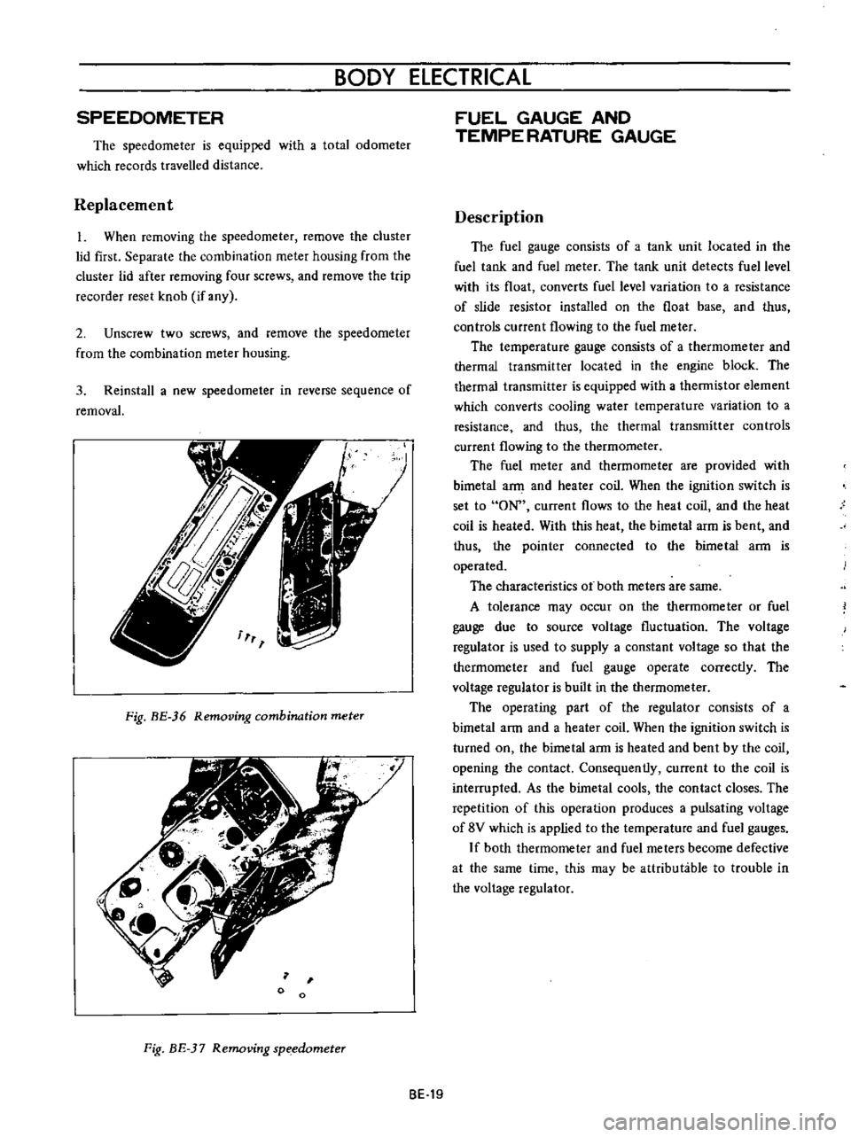
1
When
removing
the
speedometer
remove
the
cluster
lid
first
Separate
the
combination
meter
housing
from
the
cluster
lid
after
removing
four
screws
and
remove
the
trip
recorder
reset
knob
if
any
2
Unscrew
two
screws
and
remove
the
speedometer
from
the
combination
meter
housing
3
Reinstall
a
new
speedometer
in
reverse
sequence
of
removal
Fig
BE
36
Removing
combination
meter
o
Fig
BE
37
Removing
sp
edometer
FUEL
GAUGE
AND
TEMPE
RATURE
GAUGE
Description
The
fuel
gauge
consists
of
a
tank
unit
located
in
the
fuel
tank
and
fuel
meter
The
tank
unit
detects
fuel
level
with
its
float
converts
fuel
level
variation
to
a
resistance
of
slide
resistor
installed
on
the
float
base
and
thus
controls
current
flowing
to
the
fuel
meter
The
temperature
gauge
consists
of
a
thermorneter
and
thermal
transmitter
located
in
the
engine
block
The
thermal
transmitter
is
equipped
with
a
thermistor
element
which
converts
cooling
water
temperature
variation
to
a
resistance
and
thus
the
thermal
transmitter
controls
current
flowing
to
the
thermometer
The
fuel
rneter
and
thermometer
are
provided
with
bimetal
a
and
heater
coil
When
the
ignition
switch
is
set
to
ON
current
flows
to
the
heat
coil
and
the
heat
coil
is
heated
With
this
heat
the
bimetal
arm
is
bent
and
thus
the
pointer
connected
to
the
bimetal
ann
is
operated
The
characteristics
ot
both
meters
are
same
A
tolerance
may
occur
on
the
thermometer
or
fuel
gauge
due
to
source
voltage
fluctuation
The
voltage
regulator
is
used
to
supply
a
constant
voltage
so
that
the
therrnorneter
and
fuel
gauge
operate
correctly
The
voltage
regulator
is
built
in
the
thermometer
The
operating
part
of
the
regulator
consists
of
a
bimetal
arm
and
a
heater
coil
When
the
ignition
switch
is
turned
on
the
birnetal
arm
is
heated
and
bent
by
the
coil
opening
the
contact
Consequently
current
to
the
coil
is
interrupted
As
the
bimetal
cools
the
contact
closes
The
repetition
of
this
operation
produces
a
pulsating
voltage
of
8V
which
is
applied
to
the
ternperature
and
fuel
gauges
If
both
thermometer
and
fuel
meters
become
defective
at
the
same
time
this
may
be
attributable
to
trouble
in
the
voltage
regulator
BE
19
Page 255 of 513

BODY
REGULATOR
FUSE
M
TEMPE
RATURE
GAUGE
IGNITION
SWITCH
Lf
I
iT
Ji
1M
THERMAL
TRANSMITTER
I
J
0
I
GAUGE
TANK
UNIT
FUEL
TANK
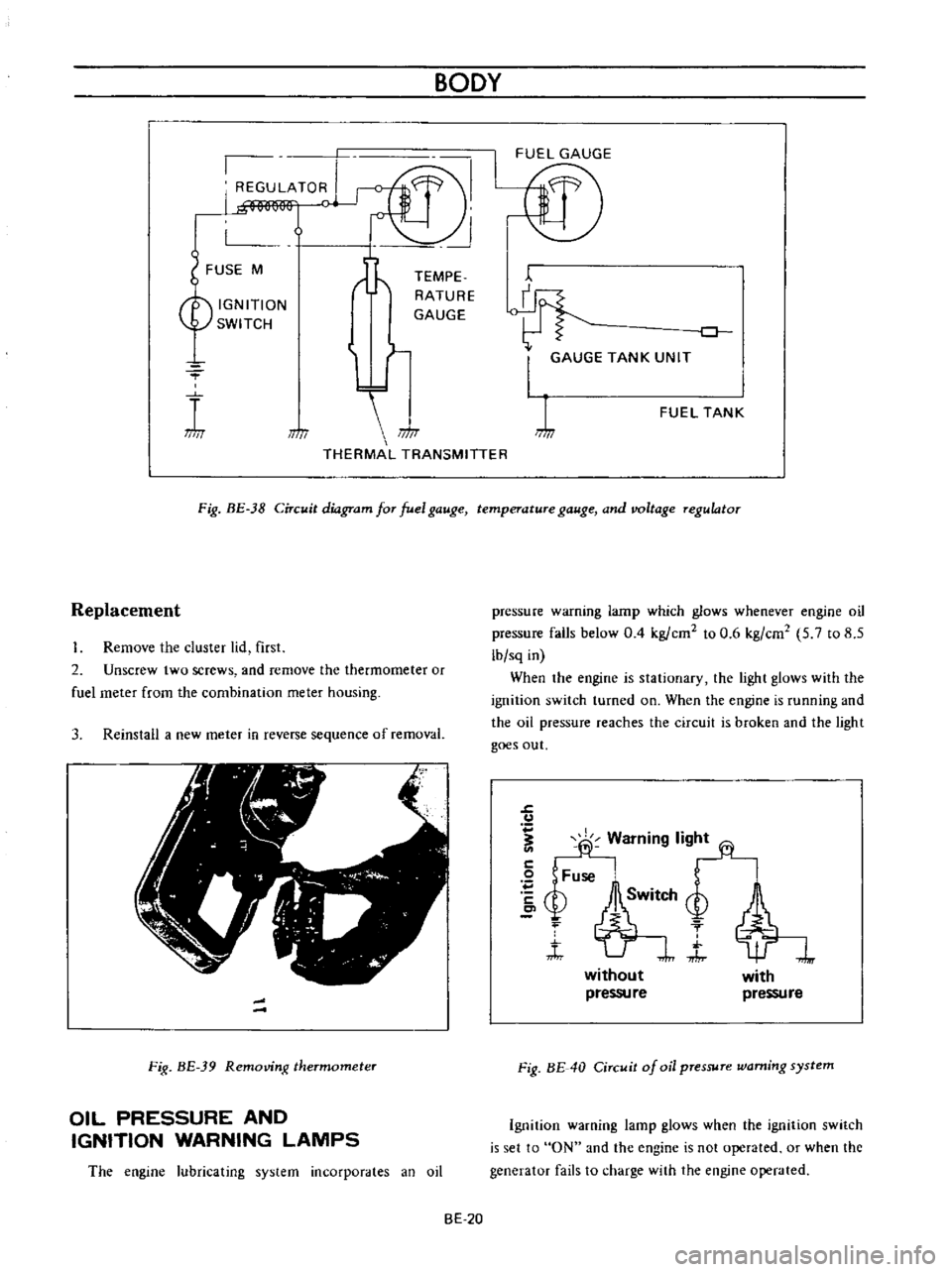
Fig
BE
38
Circuit
diagram
for
fuel
gauge
temperature
gauge
and
voltage
regulator
Replacement
Remove
the
cluster
lid
first
2
Unscrew
two
screws
and
remove
the
thermometer
or
fuel
meter
from
the
combination
meter
housing
3
Reinstall
a
new
meter
in
reverse
sequence
of
removal
Fig
BE
39
Removing
thermometer
OIL
PRESSURE
AND
IGNITION
WARNING
LAMPS
The
engine
lubricating
system
incorporates
an
oil
pressure
warning
lamp
which
glows
whenever
engine
oil
pressure
falls
below
0
4
kg
ern
to
0
6
kg
em
5
7
to
8
5
lb
sq
in
When
the
engine
is
stationary
the
light
glows
with
the
ignition
switch
turned
on
When
the
engine
is
running
and
the
oil
pressure
reaches
the
circuit
is
broken
and
the
light
goes
out
J
u
fj
Warning
lig
2
Fuse
bSM
Q
f
t
J
without
pressu
re
with
pressure
Fig
BE
40
Circuit
of
oil
pressure
warning
system
Ignition
warning
lamp
glows
when
the
ignition
switch
is
set
to
ON
and
the
engine
is
not
operated
or
when
the
generator
fails
to
charge
with
the
engine
operated
BE
20
Page 256 of 513

BODY
ElECTRICAL
When
the
ignition
switch
is
set
to
ON
the
ignition
wa
rning
circuit
is
closed
and
current
flows
flows
from
the
ignition
switch
to
the
warning
lamp
bulb
and
ground
through
the
regulator
When
the
engine
is
started
and
the
generator
comes
into
operation
the
generator
output
current
opposes
the
current
flowing
from
the
warning
lamp
in
effect
it
breaks
the
warning
circuit
ground
connection
and
the
lamp
goes
out
l
r
hffi
u
z
Ignition
switch
I
Q
6
I
0
c
M
1
E
8
ca
i
L
g
PI
lot
c
P
I
j
co
rt
0
relay
E
0
5
y
y
1
N
N
3
Alternator
Regulator
Fig
BE
41
Circuit
of
ignition
warning
system
HAND
BRAKE
WARNING
LAMP
This
lamp
functions
both
hand
brake
warning
larnp
and
BULB
SPECIFICATIONS
service
brake
line
pressure
differential
warning
lamp
When
a
difference
between
front
and
rear
brake
line
pressures
reaches
the
rated
range
13
to
17
kgfcm2
185
to
242
lb
sq
in
the
ground
circuit
for
the
warning
lamp
is
closed
and
the
warning
lamp
lights
IGNITION
SWITCH
WARNING
LAMP
L
E
WARNING
SWITCH
1
SERVICE
BRAKE
LINE
PRESSU
R
E
DIFFERENTIAL
WARNING
J
SWITCH
Fig
BE
42
Circuit
diagram
for
brake
warning
system
tern
Specifications
Square
type
meter
Round
type
meter
Meter
illumination
larnp
VoW
12
3
4
2
12
1
7
3
Turn
signal
pilot
lamp
VoW
12
3
4
2
12
1
7
2
Head
lamp
main
high
beam
VoW
12
3
4
I
12
17
1
pilot
lamp
Ignition
warning
lamp
VoW
123
4
I
12
17
1
Oil
pressure
warning
lamp
VoW
12
3
4
1
12
1
7
1
Hand
brake
warning
lamp
VoW
12
1
7
1
for
U
S
A
CANADA
Clock
illumination
lamp
VoW
123
4
I
12
17
2
Figure
encircled
in
parentheses
indicates
number
of
bulbs
used
BE
21