Page 73 of 513

CHASSIS
4
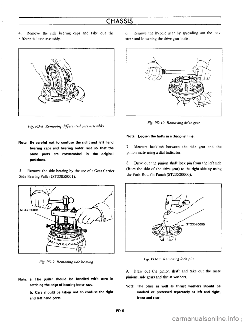
Remove
the
side
bearing
caps
and
take
out
the
differential
case
assembly
Fig
PD
8
Removing
differential
case
assembly
Note
Be
careful
not
to
confuse
the
right
and
left
hand
bearing
caps
and
bearing
outer
race
so
that
the
same
parts
are
reassembled
in
the
original
positions
5
Remove
the
side
bearing
by
the
use
of
a
Gear
Carrier
Side
Bearing
Puller
ST3305S001
o
Fig
PD
9
Removing
side
bearing
Note
a
The
puller
should
be
handled
with
care
in
catching
the
edge
of
bearing
inner
race
b
Care
should
be
taken
not
to
confuse
the
right
and
left
hand
parts
6
Remove
the
hypoid
gear
by
spreading
out
the
luck
strap
and
loosening
the
drive
gear
bolts
4
i
T
II
10
Fig
PD
I0
Removing
drive
gear
Note
Loosen
the
bolts
in
a
diagonal
line
7
Measure
backlash
between
the
side
gear
and
the
pinion
mate
using
a
dial
indicator
8
Drive
out
the
pinion
shaft
lock
pin
from
the
left
side
from
the
side
of
the
drive
gear
to
the
right
side
by
using
the
Fork
Rod
Pin
Punch
ST23520000
ST23520000
Fig
PD
l1
Removing
lock
pin
9
Draw
out
the
pinion
shaft
and
take
out
the
mate
pinions
side
gears
and
thrust
washers
Note
The
gears
as
well
as
thrust
washers
should
be
marked
or
preseNed
separately
as
left
and
right
front
and
rear
PD
6
Page 74 of 513

PROPELLER
SHAFT
DIFFERENTIAL
CARRIER
10
Measure
the
initial
turning
torque
drive
pinion
gear
by
using
Drive
Pinion
Preload
Gauge
Sn127S000
11
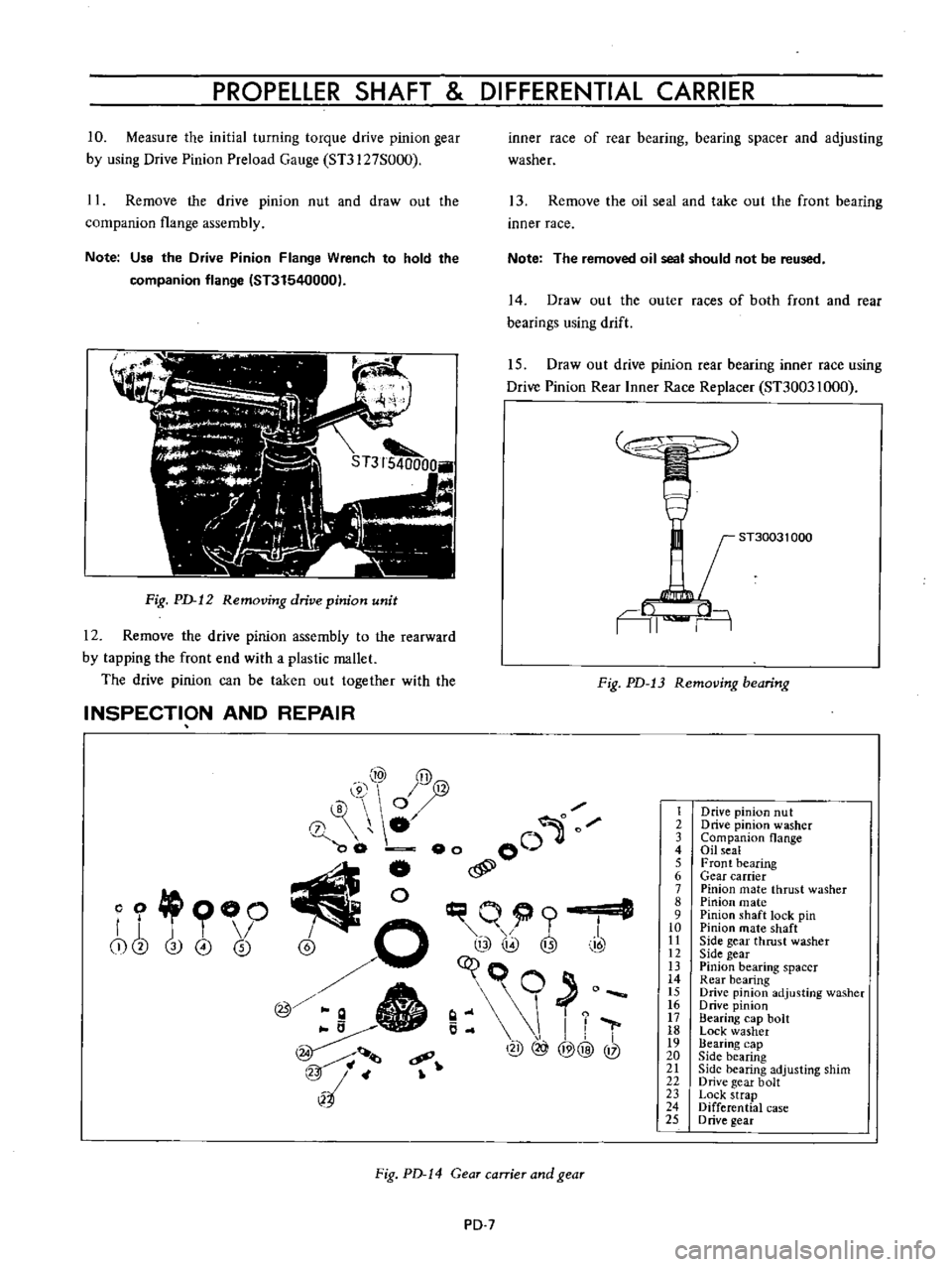
Remove
the
drive
pinion
nut
and
draw
out
the
companion
flange
assembly
Note
Use
the
Drive
Pinion
Flange
Wrench
to
hold
the
companion
flange
IST31540000
Fig
PD
12
Removing
drive
pinion
unit
12
Remove
the
drive
pinion
assembly
to
the
rearward
by
tapping
the
front
end
with
a
plastic
mallet
The
drive
pinion
can
be
taken
out
together
with
the
INSPECTION
AND
REPAIR
inner
race
of
rear
bearing
bearing
spacer
and
adjusting
washer
13
Remove
the
oil
seal
and
take
out
the
front
bearing
inner
race
Note
The
removed
oil
seal
should
not
be
reused
14
Draw
out
the
outer
races
of
both
front
and
rear
bearings
using
drift
15
Draw
out
drive
pinion
rear
bearing
inner
race
using
Drive
Pinion
Rear
Inner
Race
Replacer
ST30031000
ST30031
000
AI
n
Fig
PD
13
Removing
bearing
10
y@
@
0
0
0
00
eo
00
j
l
I
@
o
q@
@
t
I
7
c9
@
@@
@
l2
4
o
OO
r
j
T
I
i
cb
3
0
0
Fig
PD
14
Gear
carrier
and
gear
PD
7
1
2
3
4
S
6
7
8
9
10
II
12
IJ
14
IS
16
17
18
19
20
21
22
23
24
25
Drive
pinion
nut
Drive
pinion
washer
Companion
flange
Oil
seal
Front
bearing
Gear
carrier
Pinion
mate
thrust
washer
Pinion
mate
Pinion
shaft
lock
pin
Pinion
mate
shaft
Side
gear
thrust
washer
Side
gear
Pinion
bearing
spacer
Rear
bearing
Drive
pinion
adjusting
washer
o
rive
pinion
Bearing
cap
bolt
Lock
washer
Bearing
cap
Side
bearing
Side
bearing
adjusting
shim
Drive
gear
bolt
Lock
strap
Differential
case
D
rive
gear
Page 75 of 513

CHASSIS
Before
inspecting
various
parts
thoroughly
wash
them
so
that
damage
and
wear
can
be
easily
detected
Then
proceed
as
follows
Check
gear
teeth
for
scoring
cracking
and
chipping
and
make
sure
that
tooth
pattern
indicates
correct
meshing
depth
If
any
defect
is
evident
replace
parts
as
required
Note
Drive
pinion
and
drive
gear
are
supplied
for
replacement
as
a
set
therefore
should
either
part
be
damaged
replace
as
a
set
Check
the
pinion
gear
shaft
and
pinion
gear
mating
faces
for
scoring
and
signs
of
wear
and
replace
as
required
Follow
the
same
procedure
for
inner
faces
of
side
gear
and
their
seats
on
differential
case
3
Inspect
all
bearing
races
and
rollers
for
scoring
chipping
or
evidence
of
excessive
wear
They
should
be
in
tiptop
condition
not
worn
with
mirror
like
surfaces
Replace
if
there
is
a
doubt
on
their
efficiency
since
an
incorrect
bearing
operation
may
result
in
noisiness
and
gear
seizure
4
Inspect
thrust
washer
faces
Small
defects
can
be
corrected
with
emery
paper
In
ASSEMBLY
AND
AD
JUSTMENT
Tightening
torque
of
side
bearing
cap
bolts
5
to
6kg
m
36
2
to
43
4
ft
lb
co
g
E
E
on
N
case
the
clearance
between
the
side
gear
and
thrust
washer
exceeds
0
2
mm
0
0079
in
replace
the
thrust
washers
Three
kinds
of
thrust
washers
are
available
5
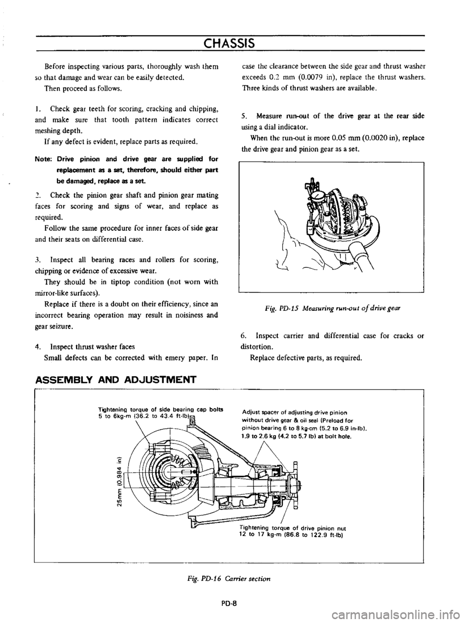
Measure
run
out
of
the
drive
gear
at
the
rear
side
using
a
dial
indicator
When
the
run
out
is
more
0
05
mm
0
0020
in
replace
the
drive
gear
and
pinion
gear
as
a
set
Fig
PD
15
Measuring
run
out
of
drive
gear
6
Inspect
carrier
and
differential
case
for
cracks
or
distortion
Replace
defective
parts
as
required
Adjust
spacer
of
adjusting
drive
pinion
without
drive
gear
oil
seal
Preload
for
pinion
bearing
6
to
8
kg
em
5
2
to
6
9
in
Ib
1
9
to
2
6
kg
4
2
to
5
7
Ib
at
bolt
hole
1
Tightening
torque
of
drive
pinion
nut
12
to
17
kg
m
86
8
to
122
9
ft
Ibl
Fig
PD
16
Carrier
section
PO
8
Page 76 of 513

PROPELLER
SHAFT
DIFFERENTIAL
CARRIER
Reassemble
the
differential
carrier
in
reverse
order
of
disassembly
The
following
instructions
for
adjustment
and
usage
of
special
tuols
are
essential
to
obtain
perfect
differential
operation
Assembling
differential
gear
case
1
Assemble
the
pinion
mate
side
gear
and
thrust
washer
in
the
differential
case
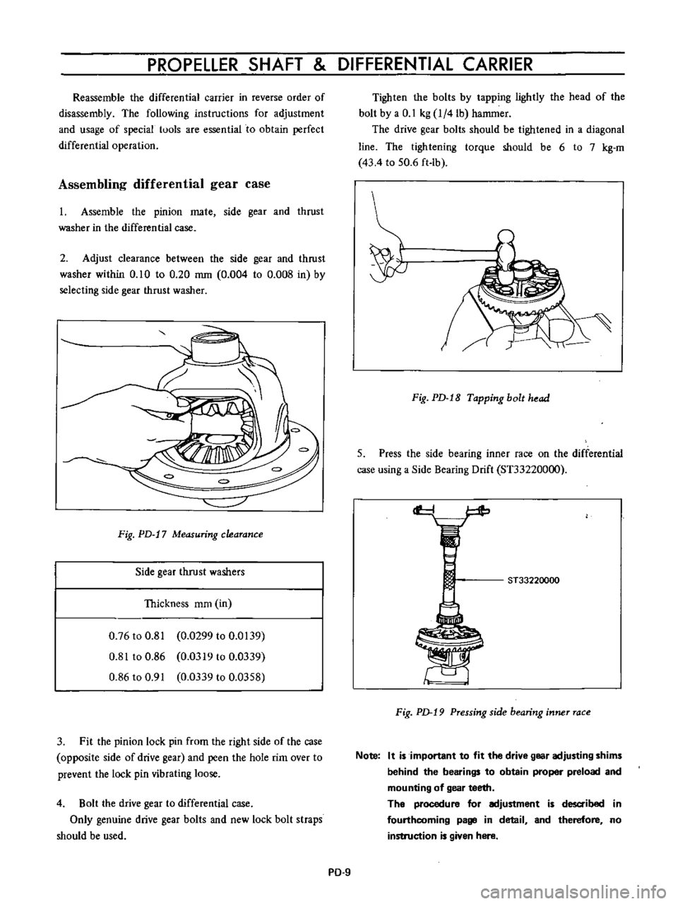
2
Adjust
clearance
between
the
side
gear
and
thrust
washer
within
0
10
to
0
20
mm
0
004
to
0
008
in
by
selecting
side
gear
thrust
washer
Fig
PD
17
Measuring
clearance
Side
gear
thrust
washers
Thickness
mm
in
0
76
to
0
81
0
0299
to
0
0139
0
81
to
0
86
0
0319
to
0
0339
0
86
to
0
91
0
0339
to
0
0358
3
Fit
the
pinion
lock
pin
from
the
right
side
of
the
case
opposite
side
of
drive
gear
and
peen
the
hole
rim
over
to
prevent
the
lock
pin
vibrating
loose
4
Bolt
the
drive
gear
to
differential
case
Only
genuine
drive
gear
bolts
and
new
lock
bolt
straps
should
be
used
Tighten
the
bolts
by
tapping
lightly
the
head
of
the
bolt
by
a
0
1
kg
l
4lb
hammer
The
drive
gear
bolts
should
be
tightened
in
a
diagonal
line
The
tightening
torque
should
be
6
to
7
kg
m
43
4
to
50
6
ft
lb
Fig
PD
18
Tapping
bolt
head
5
Press
the
side
bearing
inner
race
on
the
differential
case
using
a
Side
Bearing
Drift
ST33220000
cf
ST33220000
F
ig
p
19
Pressing
side
bearing
inner
race
Note
It
is
important
to
fit
the
drive
gear
adjusting
shims
behind
the
bearings
to
obtain
proper
preload
and
mounting
of
gear
teeth
The
procedure
for
adjustment
is
d
ibed
in
fourthcoming
page
in
detail
and
therefore
no
instruction
is
given
here
PD
9
Page 77 of 513

CHASSIS
Setting
and
adjusting
drive
pinion
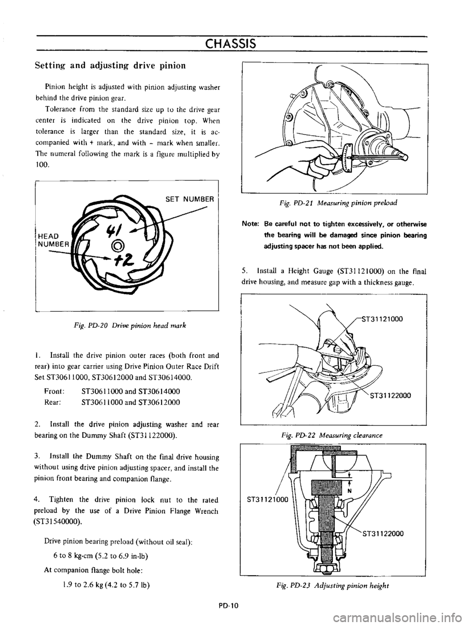
Pinion
height
is
adjusted
with
pinion
adjusting
washer
behind
the
drive
pinion
gear
Tolerance
from
the
standard
size
up
to
the
drive
gear
center
is
indicated
on
the
drive
pinion
top
When
tolerance
is
larger
than
the
standard
size
it
is
ac
companied
with
mark
and
with
mark
when
smaller
The
numeral
following
the
mark
is
a
figure
multiplied
by
100
HEAD
NUMBER
FiR
PD
20
Drive
pinion
head
mark
Install
the
drive
pinion
outer
races
both
front
and
rear
into
gear
carrier
using
Drive
Pinion
Outer
Race
Drift
Set
STJ061
1000
STJ0612000
and
Sn0614000
Froot
STJ061
1000
and
STJ0614000
Rear
STJ061
1000
and
STJ0612000
2
Install
the
drive
pinion
adjusting
washer
and
rear
bearing
on
the
Dummy
Shaft
STJI122000
3
Install
the
Dummy
Shaft
on
the
fmal
drive
housing
without
using
drive
pinion
adjusting
spacer
and
install
the
pinion
front
bearing
and
companion
flange
4
Tighten
the
drive
pinion
lock
nut
to
the
rated
preload
by
the
use
of
a
Drive
Pinion
Flange
Wrench
SnI540000
Drive
pinion
bearing
preload
without
oil
seal
6
to
8
kg
cm
5
2
to
6
9
in
lb
At
companion
flange
bolt
hole
19
to
2
6
kg
4
2
to
5
7lb
PD
l0
Fig
PD
21
Measuring
pinion
preload
Note
Be
careful
not
to
tighten
excessively
or
otherwise
the
bearing
will
be
damaged
since
pinion
bearing
adjusting
spacer
has
not
been
applied
5
Install
a
Height
Gauge
STJI12l000
on
the
flnal
drive
housing
and
measure
gap
with
a
thickness
gauge
ST31122000
Fig
PD
22
Measuring
clearance
r
ST31121000
ST31122000
Fig
PD
23
Adjusting
pinion
height
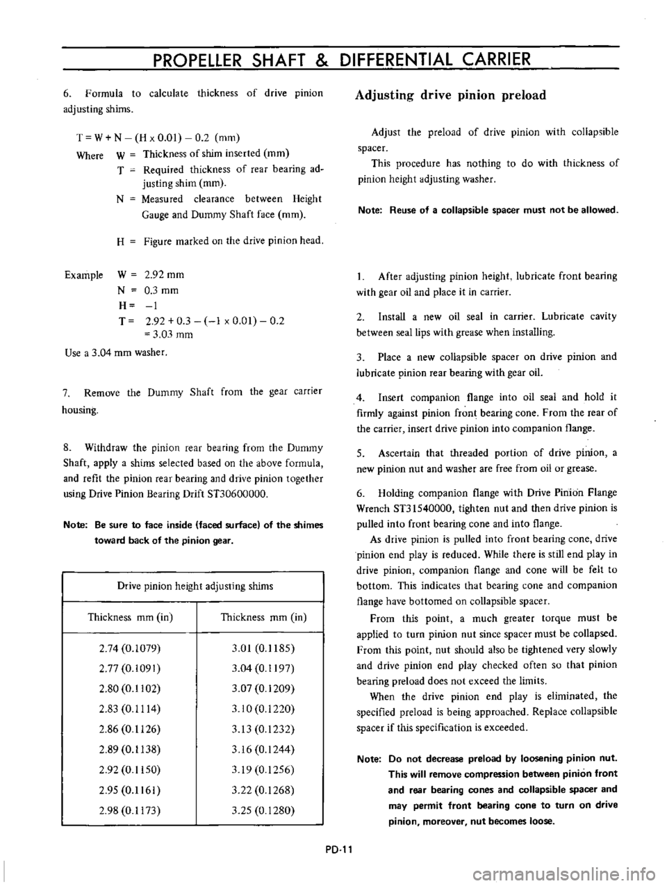
Page 78 of 513

PROPELLER
SHAFT
DIFFERENTIAL
CARRIER
6
Formula
to
calculate
thickness
of
drive
pinion
adjusting
shims
T
W
N
H
x
0
01
0
2
mm
Where
W
Thickness
of
shim
inserted
mm
T
Required
thickness
of
rear
bearing
ad
justing
shim
mm
N
Measured
clearance
between
Height
Gauge
and
Dummy
Shaft
face
mm
H
Figure
marked
on
the
drive
pinion
head
Example
W
2
92
mm
N
0
3
mm
H
1
T
2
92
0
3
1
x
0
01
0
2
3
03
mm
Use
a
3
04
mm
washer
7
Remove
the
Dummy
Shaft
from
the
gear
carrier
housing
8
Withdraw
the
pinion
rear
bearing
from
the
Dummy
Shaft
apply
a
shims
selected
based
on
the
above
formula
and
refit
the
pinion
rear
bearing
and
drive
pinion
together
using
Drive
Pinion
Bearing
Drift
STJ0600000
Note
Be
sure
to
face
inside
faced
surface
of
the
shimes
toward
back
of
the
pinion
gear
Drive
pinion
height
adjusting
shims
Thickness
mm
in
Thickness
mm
in
2
74
0
1079
2
77
0
i091
2
80
0
1102
2
83
0
1114
2
86
0
1126
2
89
0
1138
2
92
0
1150
2
95
0
1161
2
98
0
1173
3
01
0
1185
3
04
0
1197
3
07
0
1209
3
10
0
i
220
3
13
0
1232
3
16
0
1244
319
0
1256
3
22
0
1268
3
25
0
1280
PD
Adjusting
drive
pinion
preload
Adjust
the
preload
of
drive
pinion
with
collapsible
spacer
This
procedure
has
nothing
to
do
with
thickness
of
pinion
height
adjusting
washer
Note
Reuse
of
a
collapsible
spacer
must
not
be
allowed
After
adjusting
pinion
height
lubricate
front
bearing
with
gear
oil
and
place
it
in
carrier
2
Install
a
new
oil
seal
in
carrier
Lubricate
cavity
between
seal
lips
with
grease
when
installing
3
Place
a
new
collapsible
spacer
on
drive
pinion
and
lubricate
pinion
rear
bearing
with
gear
oil
4
Insert
companion
flange
into
oil
seal
and
hold
it
firmly
against
pinion
fron
bearing
cone
From
the
rear
of
the
carrier
insert
drive
pinion
into
companion
flange
5
Ascertain
that
threaded
portion
of
drive
pinion
a
new
pinion
nut
and
washer
are
free
from
oil
or
grease
6
Holding
companion
flange
with
Drive
Pinion
Flange
Wrench
ST31540000
tighten
nut
and
then
drive
pinion
is
pulled
into
front
bearing
cone
and
into
flange
As
drive
pinion
is
pulled
into
front
bearing
cone
drive
pinion
end
play
is
reduced
While
there
is
still
end
play
in
drive
pinion
companion
flange
and
cone
will
be
felt
to
bottom
This
indicates
that
bearing
cone
and
companion
flange
have
bottomed
on
collapsible
spacer
From
this
point
a
much
greater
torque
must
be
applied
to
turn
pinion
nut
since
spacer
must
be
collapsed
From
this
point
nut
should
also
be
tightened
very
slowly
and
drive
pinion
end
play
checked
often
so
that
pinion
bearing
preload
does
not
exceed
the
limits
When
the
drive
pinion
end
play
is
eliminated
the
specified
preload
is
being
approached
Replace
collapsible
spacer
if
this
specification
is
exceeded
Note
Do
not
decrease
preload
by
loosening
pinion
nut
This
will
remove
compression
between
pinion
front
and
rear
bearing
cones
and
collapsible
spacer
and
may
permit
front
bearing
cone
to
turn
on
drive
pinion
moreover
nut
becomes
loose
Page 79 of 513

CHASSIS
7
Turn
drive
pinion
in
both
directions
several
times
to
set
bearing
rollers
And
adjust
bearing
preload
to
specifi
cations
Drive
pinion
bearing
preload
with
oil
seal
7
to
9
kg
cm
6
1
to
7
8
in
1b
At
companion
flange
bolt
hole
2
25
to
2
95
kg
4
96
to
6
50
1b
Pinion
nut
tightening
torque
12
to
17
kg
m
86
8
to
122
9
ft
1b
Fig
PD
24
Measuring
pinion
preload
Setting
and
adjusting
side
bearing
shims
When
reassembling
the
side
bearing
without
replacing
be
sure
to
install
a
shim
having
same
thickness
as
that
before
disassembly
The
following
instructions
apply
when
the
hearing
is
replaced
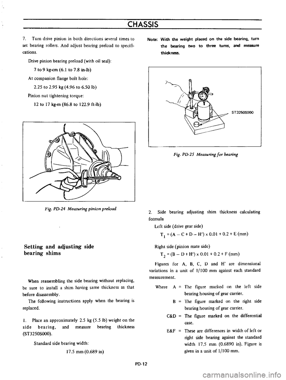
I
Place
an
approximately
2
5
kg
5
5
Ib
weight
on
the
side
bearing
and
measure
bearing
thickness
ST3250S000
Standard
side
bearing
width
17
5
mm
0
689
in
Note
With
the
weight
placed
on
the
side
bearing
turn
the
bearing
two
to
three
turns
and
measure
thickn
1
ST3250S000
Fig
PD
25
Measuring
for
bearing
2
Side
bearing
adjusting
shim
thickness
calculating
formula
Left
side
drive
gear
side
Tl
A
C
D
H
xO
01
0
2
E
mm
Right
side
pinion
mate
side
T
2
B
D
H
x
0
01
0
2
F
mm
Figures
for
A
B
C
D
and
H
are
dimensional
variations
in
a
unit
of
1
100
mm
against
each
standard
measurement
Where
A
The
figure
marked
on
the
left
side
bearing
housing
of
gear
carrier
The
figure
marked
on
the
right
side
bearing
housing
of
gear
carrier
The
figure
marked
on
the
differential
case
B
C
D
E
F
These
are
differences
in
width
of
left
or
right
side
bearing
against
the
standard
width
17
5
mm
0
6890
in
Figure
is
given
in
a
unit
of
1
100
mm
PD
12
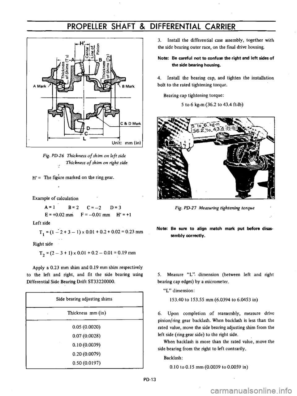
Page 80 of 513

PROPELLER
SHAFT
DIFFERENTIAL
CARRIER
C
DMark
Unit
mm
in
Fig
PD
26
Thickness
of
shim
on
left
side
Thickness
of
shim
on
right
side
H
The
figure
marked
on
the
ring
gear
Example
of
calculation
A
I
B
2
E
0
02
mni
Left
side
C
2
D
3
F
O
Olmm
H
1
TJ
1
2
3
1
xO
01
0
2
0
02
0
23
mm
Right
side
T
2
2
3
1
x
0
01
0
2
0
01
0
19
mm
Apply
a
0
23
mm
shim
and
0
19
mm
shim
respectively
to
the
left
and
right
and
fit
the
side
bearing
using
Differential
Side
Bearing
Drift
ST33220000
Side
bearing
adjusting
shims
Thickness
mm
in
0
05
0
0020
0
07
0
0028
0
10
0
0039
0
20
0
0079
0
50
0
0197
PD
13
3
Install
the
differential
case
assembly
together
with
the
side
bearing
outer
race
on
the
final
drive
housing
Note
Be
careful
not
to
confuse
the
right
and
left
sides
of
the
side
bearing
housing
4
Install
the
bearing
cap
and
tighten
the
installation
bolt
to
the
rated
tightening
torque
Bearing
cap
tightening
torque
5
to
6
kg
m
36
2
to
43
4
ft
1b
Fig
PD
27
Measuring
tightening
torque
Note
Be
sure
to
align
match
mark
put
before
disas
sembly
correctly
5
Measure
L
dimension
between
left
and
right
bearing
cap
edges
by
a
micrometer
L
dimension
153
40
to
153
55
mm
6
0394
to
6
0453
in
6
Upon
completion
of
reassembly
measure
drive
pinion
ring
gear
backlash
When
backlash
is
less
than
the
rated
value
move
the
side
bearing
adjusting
shim
from
the
left
side
ring
gear
side
to
the
right
side
When
backlash
is
more
than
the
rated
value
move
the
side
bearing
from
the
right
to
left
contrarily
Backlash
0
10
to
0
15
mm
0
0039
to
0
0059
in