Page 49 of 513

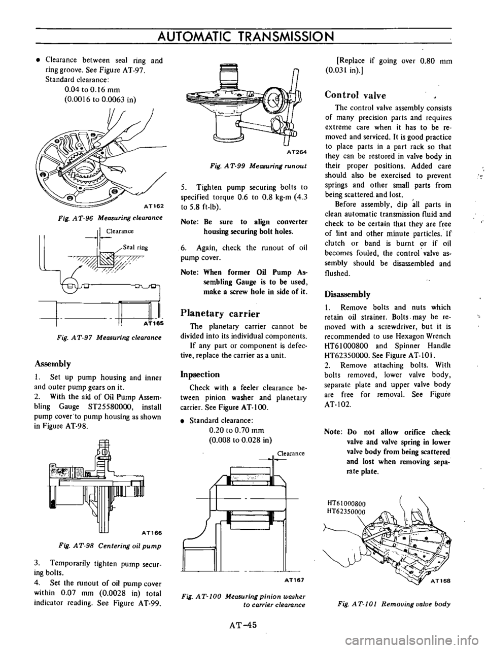
Clearance
between
seal
ring
and
ring
groove
See
Figure
AT
97
Standard
clearance
0
04toO
16mm
0
0016
to
0
0063
in
AT162
Fig
A
T
96
Measuring
clearance
I
earance
I
Seal
rIng
0d
t
AT185
II
Fig
AT
97
Measuring
clearance
Assembly
1
Set
up
pump
housing
and
inner
and
outer
pump
gears
on
it
2
With
the
aid
of
Oil
Pump
Assem
bling
Gauge
ST255800oo
install
pump
cover
to
pump
housing
as
shown
in
Figure
AT
98
lnnrr
i
rnl
l
AT166
Fig
A
T
98
Centering
oil
pump
3
Temporarily
tighten
pump
secur
ing
bolts
4
Set
the
runout
of
oil
pump
cover
within
0
07
mm
0
0028
in
total
indicator
reading
See
Figure
A
T
99
AUTOMATIC
TRANSMISSION
AT264
Fig
A
T
99
Measuring
run
out
5
Tighten
pump
securing
bolts
to
specified
torque
0
6
to
0
8
kg
m
4
3
to
5
8
ft
Ib
Note
Be
sure
to
align
converter
housing
securing
bolt
holes
6
Again
check
the
runout
of
oil
pump
cover
Note
When
former
Oil
Pump
As
sembling
Gauge
is
to
be
used
make
a
screw
hole
in
side
of
it
Planetary
carrier
The
planetary
carrier
cannot
be
divided
into
its
individual
components
If
any
part
or
component
is
defec
tive
replace
the
carrier
as
a
unit
Inpsection
Check
with
a
feeler
clearance
be
tween
pinion
washer
and
planetary
carrier
See
Figure
AT
100
Standard
clearance
0
20
to
0
70
mm
0
008
to
0
028
in
Clearance
I
LJ
b
II
I
AT161
Fig
AT
100
Mea
uring
pinion
washer
to
carrier
clearance
AT
45
Replace
if
going
over
0
80
mm
0
031
in
Control
valve
The
control
valve
assembly
consists
of
many
precision
parts
and
requires
extreme
care
when
it
has
to
be
re
moved
and
serviced
It
is
good
practice
to
place
parts
in
a
part
rack
so
that
they
can
be
restored
in
valve
body
in
their
proper
positions
Added
care
should
also
be
exercised
to
prevent
springs
and
other
small
parts
from
being
scattered
and
lost
Before
assembly
dip
all
parts
in
clean
automatic
transmission
nuid
and
check
to
be
certain
that
they
are
free
of
lint
and
other
minute
particles
If
clutch
or
band
is
burnt
or
if
oil
becomes
fouled
the
control
valve
as
sembly
should
be
disassembled
and
flushed
Disassembly
1
Remove
bolts
and
nuts
which
retain
oil
strainer
Bolts
may
be
re
moved
with
a
screwdriver
but
it
is
recommended
to
use
Hexagon
Wrench
HT61000800
and
Spinner
Handle
HT62350000
See
Figure
AT
10
I
2
Remove
attaching
bolts
With
bolts
removed
lower
valve
body
separate
plate
and
upper
valve
body
are
free
for
removal
See
Figure
AT
102
Note
Do
not
allow
orifice
check
valve
and
valve
spring
in
lower
valve
body
from
being
scattered
and
lost
when
removing
sepa
rate
plate
HT61000BOO
HT62350000
Fig
AT
101
Removing
valve
body
Page 50 of 513

I
Fig
AT
102
Removing
5
parote
plate
3
Pull
out
manual
valve
as
shown
in
Figure
AT
103
4
Remove
side
plate
Take
out
1st
2nd
shift
valve
2nd
3rd
shift
valve
pressure
modifier
valve
and
three
valve
springs
See
Figure
AT
I04
CHASSIS
AT170
Fig
AT
103
Removing
manual
valve
Note
Do
not
work
it
off
with
screw
drivers
to
avoid
damaging
machine
screws
5
Remove
side
plate
pull
out
pres
sure
regulator
valve
second
lock
valve
pressure
regulator
plug
and
two
valve
springs
sp
m
Pressure
regutlltor
sleeve
C
Prt
ssure
P
elato
piug
IZt
1
2iid3
d
h
1
alve
7
I
Solenoid
down
skutt
Throttle
back
up
alw
p
u
modif
Second
lock
alve
MllllU81
1st
2nd
shift
2nd
3rd
shift
Inspection
I
Check
valves
for
sign
of
burning
and
if
necessary
replace
2
Check
to
be
certain
that
oil
strainer
is
in
good
condition
If
found
damaged
in
any
ffi3nner
discard
3
Test
valve
springs
for
weakened
egulator
alve
3
1
ott
jj
r
of
U
d
4
t
i
i
J
j
r
r
lC
i
i
4
i
I
5
j
AT171
Fig
A
T
l
04
Removing
8ide
plate
6
Remove
side
plate
With
side
plate
removed
solenoid
downshift
valve
throttle
back
up
valve
vacuum
throttle
valve
2nd
3rd
timing
valve
and
three
valve
springs
are
free
for
removal
2nd
3rd
timing
3
ve
i
Vacuum
Ihrotlle
alve
aive
Fig
AT
L05
Components
parts
of
control
value
tension
if
necessary
replace
4
Examine
if
there
is
any
sign
of
damage
or
score
marks
on
separate
plate
If
left
unheeded
oil
will
bypass
correct
oil
passages
causing
many
types
of
abnormalities
in
the
system
AT
46
5
Check
oil
passages
in
valve
body
for
sign
of
damage
and
other
condi
tions
which
might
interfere
with
prop
er
valve
operation
6
Check
bolts
for
stripped
threads
Replace
as
required
Page 51 of 513

AUTOMATIC
TRANSMISSIO
N
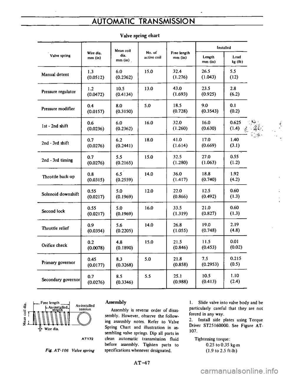
Valve
pring
chart
Installed
Wiredia
Mean
coil
No
of
Free
length
Valve
spring
mm
in
dia
active
coil
mm
in
Length
Load
mm
in
mm
in
kg
Ib
1
3
6
0
15
0
32
4
26
5
5
5
Manual
detent
0
0512
0
2362
1
276
1
043
12
1
2
10
5
13
0
43
0
23
5
2
8
Pressure
regulator
0
0472
0
4134
1
693
0
925
6
2
0
4
8
0
5
0
18
5
9
0
0
1
Pressure
modifier
0
0157
0
3150
0
728
0
3543
0
2
0
6
6
0
16
0
32
0
16
0
0
625
it
J
1st
2nd
shift
0
0236
0
2362
1
260
0
630
14
i
o
0
7
6
2
18
0
41
0
17
0
140
2nd
3
rd
shift
0
0276
0
2441
1
614
0
669
3
1
0
7
5
5
15
0
32
5
27
0
0
55
2nd
3rd
timing
0
0276
0
2165
1
280
1
063
1
2
Throttle
back
up
0
8
6
5
14
0
36
0
18
8
1
92
0
0315
0
2559
1417
0
740
4
2
0
55
5
0
12
0
22
0
12
5
0
60
Solenoid
downshift
0
0217
0
1969
0
866
0
492
1
3
0
55
5
0
16
0
33
5
21
0
0
60
Second
lock
0
0217
0
1969
1
319
0
827
1
3
0
9
5
6
14
0
26
8
19
0
2
19
Throttle
relief
0
0354
0
2205
1
055
0
748
4
8
0
2
4
8
15
0
21
5
11
5
0
01
Orifice
check
0
0078
0
1890
0
846
0
453
0
02
0
45
8
3
5
0
21
8
7
5
0
215
Primary
governor
0
0177
0
3268
0
858
0
2953
0
5
0
7
8
5
5
5
25
1
10
5
1
10
Secondary
governor
0
0276
0
3346
0
988
0
413
2
4
Free
length
L
U
d
As
ins
alled
I
t
LldnstjH
e
t
n
Ion
J
I
I
Assembly
Assembly
is
reverse
order
of
disas
sembly
However
observe
the
follow
ing
assembly
notes
Refer
to
Valve
Spring
Chart
and
illustration
in
as
sembling
valve
springs
Dip
all
parts
in
clean
automatic
transmission
fluid
before
assembly
Tighten
parts
to
specifications
whenever
designated
AT172
Fig
AT
106
Value
pring
AT
47
I
Slide
valve
into
valve
body
and
be
particularly
careful
that
they
are
not
forced
in
any
way
2
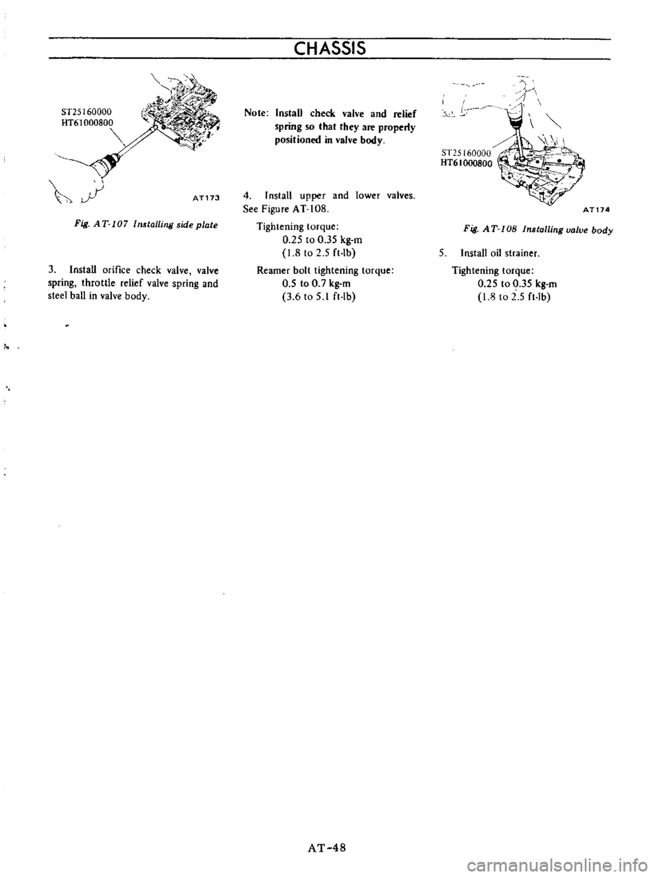
Install
side
plates
using
Torque
Driver
ST25I60000
See
Figure
AT
107
Tightening
torque
0
25
to
0
35
kg
m
1
9
to
2
5
ft
Ib
Page 52 of 513
ST25
1
60000
HT6
1
000800
r
if
AT173
Fig
AT
107
Installing
side
plate
3
Install
orifice
check
valve
valve
spring
throttle
relief
valve
spring
and
steel
ball
in
valve
body
CHASSIS
Note
Install
check
valve
and
relief
spring
so
that
they
are
properly
positioned
in
valve
body
4
I
nstall
upper
and
lower
valves
See
Figure
AT
108
Tightening
torque
0
25
to
0
35
kg
m
1
8
to
2
5
ft
Ib
Reamer
bolt
tightening
torque
0
5
to
0
7
kg
m
3
6
to
5
1
ft
Ib
AT
48
A
t
ST25160000
HT61ooo800
AT174
Fig
AT
lOB
Installingualve
body
5
Install
oil
strainer
Tightening
torque
0
25
to
0
35
kg
m
1
8
to
2
5
ft
Ib
Page 53 of 513

AUTOMATIC
TRANSMISSIO
N
TROUBLE
DIAGNOSES
AND
ADJUSTMENT
INSPECTION
AND
ADJUSTMENT
BEFORE
TROUBLE
DIAGNOSIS
Testing
instrument
for
inspection
Checking
oil
level
Inspection
and
repair
of
oil
leakage
Checking
engine
idling
rpm
Checking
and
adjusting
kick
down
switch
and
downshift
solenoid
Inspection
and
adjustment
of
manual
linkage
Checking
and
adjusting
inhibitor
switch
STALL
TEST
Stall
test
procedures
Judgement
As
the
troubles
on
the
automatic
transmission
can
be
mostly
repaired
by
doing
simple
adjustment
so
do
not
disassemble
immediately
if
the
auto
m
tic
transmission
is
in
trouble
Firstly
inspect
and
adjust
the
auto
matic
transmission
with
mounting
on
vehicle
by
observing
the
trouble
shooting
chart
If
the
trouble
could
not
be
solved
by
this
procedure
then
remove
and
disassemble
the
automatic
transmis
sion
It
is
advisable
to
check
overhaul
and
repair
each
point
in
the
order
itemized
in
the
trouble
shooting
chart
l
In
the
trouble
shooting
chart
the
diagnosis
items
are
arranged
in
the
order
from
easy
to
difficult
and
there
fore
please
follow
these
items
The
transmission
should
not
be
removed
unless
necessary
2
The
test
and
adjustment
for
trou
ble
diagnosis
should
be
made
on
the
basis
of
standard
values
and
the
data
should
be
recorded
ROAD
TEST
Car
speed
at
gear
shift
Checking
speed
changing
condition
Checking
items
during
speed
change
Shift
schedule
LINE
PRESSURE
TEST
Line
pressure
governor
feed
pressure
Judgement
in
measuring
line
pressure
TROUBLE
SHOOTING
CHART
Inspecting
items
Trouble
shooting
chart
for
3N71
B
Automatic
Transmission
Trouble
shooting
guide
for
3N718
Automatic
Transmission
CONTENTS
AT
49
AT
49
AT
49
AT
50
AT
50
AT
50
AT
51
AT
51
AT
51
AT51
AT
52
INSPECTION
AND
AD
JUSTMENT
BEFORE
TROUBLE
DIAGNOSIS
Testing
instrument
for
inspection
1
Engine
tachometer
2
Vacuum
gauge
3
Oil
pressure
gauge
It
is
convenient
to
install
these
instruments
in
a
way
that
allows
meas
urements
to
be
made
from
the
driver
s
seat
Checking
oil
level
In
checking
the
automatic
transmis
sion
the
oil
level
and
the
condition
of
oil
around
the
oil
level
gauge
should
be
examined
every
5
000
km
3
000
miles
These
steps
are
easy
and
effec
live
in
trouble
shooting
as
some
change
of
oil
conditions
are
linked
with
developed
troubles
in
many
cases
AT
49
AT
52
AT
52
AT
53
AT
53
AT
53
AT
53
AT
53
AT
54
AT
54
AT
54
AT
55
AT
5B
For
instance
Lack
of
oil
causes
defective
opera
tion
by
making
the
clutches
and
brakes
slip
developing
severe
wear
The
cause
of
this
operation
is
that
the
oil
pump
has
begun
to
suck
air
which
caused
oil
foaming
thus
rapidly
deteriora
ting
the
oil
quality
and
pro
ducing
sludge
and
varnish
Meanwhile
excessive
oil
is
also
bad
as
in
the
case
of
a
lack
of
oil
because
of
oil
foaming
by
being
stirred
up
by
the
gears
Moreover
in
high
speed
driving
with
excessive
oil
in
the
trans
mission
the
oil
often
blows
out
from
the
breather
I
Measuring
oil
level
When
checking
the
fluid
level
start
the
engine
and
run
it
until
normal
operating
temperatures
oil
tempera
ture
50
to
800e
122
to
176
F
Approximately
ten
minute
operation
will
elevate
the
temperature
to
this
range
and
enigne
idling
conditions
are
stabilized
Then
apply
the
brakes
and
move
the
transmission
shift
lever
Page 54 of 513

through
all
drive
positions
and
place
the
lever
in
park
P
position
In
this
inspection
the
car
must
be
placed
on
a
level
surface
The
amount
of
the
oil
varies
with
the
temperature
As
a
rule
the
oil
level
must
be
measured
after
its
tempera
ture
becomes
sufficiently
high
I
Fill
the
oil
to
the
line
H
The
difference
of
capacities
between
both
H
and
L
is
approximately
0
4
liter
7
8
U
S
pt
3
4
Imper
pt
and
therefore
take
care
not
to
fill
beyond
the
line
H
2
At
the
time
of
the
above
topping
up
and
changing
of
oil
care
should
be
taken
of
to
prevent
mixing
the
oil
with
dust
and
water
2
Inspecting
oil
condition
The
condition
of
oil
sticking
to
the
level
gauge
indicates
whether
to
over
haul
and
repair
the
transmission
or
look
for
the
defective
part
If
the
oil
has
deteriorated
into
a
varnish
like
quality
it
causes
the
con
trol
valve
to
stick
The
blackened
oil
gives
the
proof
of
the
burned
clutch
brake
band
etc
In
these
cases
the
transmission
must
be
replaced
Notes
a
In
oil
level
checking
use
special
paper
waste
to
handle
the
level
gauge
and
take
care
not
to
let
the
scraps
of
paper
and
cloth
tick
to
the
gauge
b
Insert
the
gauge
fully
and
take
it
out
quickly
before
splashing
oil
adheres
to
the
gauge
and
theu
observe
the
level
c
Use
automatic
transmission
fluid
having
DEXRON
iden
tIficatIon
only
in
the
3N71
B
automatic
transmission
d
Pay
atteutIon
because
the
oil
to
be
used
dIffers
from
that
i
used
in
the
Nissan
Full
Automatic
Transmission
3N7IA
Never
mix
the
oil
with
that
CHASSIS
Inspection
and
repair
of
oil
leakage
When
oil
leakage
takes
place
the
portion
near
the
leakage
is
covered
with
oil
presenting
difficulty
in
de
tecting
the
spot
Therefore
the
places
where
oil
seals
and
gaskets
are
equipped
are
enumerated
below
I
Converter
housing
The
rubber
ring
of
oil
pump
hous
ing
The
oil
eaI
of
oil
pump
housing
The
oil
seal
of
engine
crankshaft
The
bolts
of
converter
housing
to
case
2
Transmission
and
rear
extension
Junction
of
transmission
and
rear
extension
Oil
tube
connectors
Oil
pan
Oil
pressure
inspection
holes
Refer
to
Figure
AT
112
The
mounting
portion
of
vacuum
diaphragm
and
downshift
solenoid
Breather
and
oil
charging
pipe
Speedometer
pinion
sleeve
The
oil
seal
of
rear
extension
To
exactly
locate
the
place
of
oil
leakage
proceeds
as
follows
Place
the
vehicle
in
a
pit
and
by
sampling
the
leaked
oil
examine
whe
ther
it
is
the
torq
le
converter
oil
or
not
The
torque
converter
oil
assumes
color
like
red
wine
when
shipped
from
the
factory
so
it
is
ea
ily
distin
guished
from
engine
oil
or
gear
oil
Cleanly
wipe
off
the
leaking
oil
and
dust
and
detect
the
spot
of
oil
leakage
Use
nonflammable
organic
solvent
such
as
carbon
tetrachloride
for
wip
ing
Raise
the
oil
temperature
by
op
erating
the
engine
and
shift
the
lever
to
0
to
heighten
the
oil
pressure
The
spot
of
oil
leakage
will
then
be
found
more
easily
Note
A
the
oil
leakage
from
the
breather
does
not
take
place
except
when
running
at
high
speed
it
is
impossible
to
locate
the
spot
of
leakage
with
vehicle
stalled
AT
50
Checking
engine
idling
rprn
The
engine
idling
revolution
should
be
properly
adjusted
If
the
engine
revolution
is
too
low
the
engine
does
not
operate
smoothly
and
if
too
high
a
strong
shock
or
creep
develops
when
changing
over
from
N
to
D
or
R
Specified
idling
speed
650
rpm
at
D
position
800
rpm
at
N
position
Checking
and
adjusting
kick
down
switch
and
downshift
solenoid
When
the
kick
down
operation
is
not
made
properly
or
the
speed
chang
ing
point
is
too
high
check
the
kick
down
switch
downshift
solenoid
and
wiring
between
them
When
the
igni
tion
key
is
positioned
at
the
1st
stage
and
the
accelerator
pedal
is
depressed
deeply
the
switch
contact
should
be
closed
and
the
solenoid
should
click
If
it
does
not
click
it
indicates
a
defect
Then
check
each
part
with
the
testing
instruments
See
Figure
AT
I09
0
0
1
M
r
7
I
Y
ATl08
Fig
A
T
l
09
Downshift
solenoid
Note
Watch
for
oil
leakage
from
transmission
case
Page 55 of 513

c
Inspection
and
adJu
Stmenf
trouble
first
check
the
linhge
f
no
1
i
jI
fect
is
found
in
the
lin1
age
check
of
manu
a
l
liiiJ
i
the
inhibitor
switch
Th
d
1F
aI
S
t
th
I
I
f
e
a
JU
i
J
u
epara
e
e
range
se
eet
ever
rom
Iy
important
ii
s3
ns
etion
of
oil
the
lower
shift
rod
and
turn
the
range
1
level
for
the
automatiC
tran
smission
select
lever
to
N
Therefore
great
care
should
be
exer
Note
In
the
position
N
the
slot
of
cised
because
defective
adjustment
will
the
manual
shaft
is
vertical
result
in
the
breakdown
of
the
trans
By
the
use
of
the
tester
check
the
two
bIack
yellow
BY
wires
from
the
inhibitor
switch
in
the
ranges
N
and
P
and
the
two
red
bIack
RB
wires
in
the
range
R
for
continuity
Turn
range
select
lever
to
both
directions
from
each
lever
set
position
and
check
each
continuity
range
It
is
normal
if
the
electricity
is
on
while
the
lever
is
within
an
angle
of
about
3
0
on
both
sides
from
each
lever
set
line
How
ever
if
its
continuity
range
is
obvi
ously
unequal
on
both
sides
the
adjustment
is
required
f
any
malfunction
is
found
un
screw
the
fastening
nut
of
the
range
selector
lever
and
two
fastening
bolts
of
the
switch
body
and
then
remove
the
machine
screw
under
the
switch
body
Adjust
the
manual
shaft
correct
ly
to
the
position
N
by
means
of
the
selector
lever
When
the
slot
of
the
shaft
becomes
vertical
the
detent
works
to
position
the
shaft
correctly
with
a
click
sound
Move
the
switch
slightly
aside
so
that
the
screw
hole
will
be
aligned
with
the
pin
hole
of
the
internal
rotor
combined
with
the
manual
shaft
and
check
their
alignment
by
inserting
a
1
5
0101
0
0591
in
diameter
pin
into
the
holes
If
the
alignment
is
made
correct
1
5ten
the
switch
body
with
the
bolts
pull
out
the
pin
and
tighten
up
the
screw
again
into
the
hole
and
fasten
the
selector
lever
as
before
Check
over
again
the
continuity
with
the
tester
If
the
malfunction
still
remains
replace
the
inhibitor
switch
mission
Inspection
Pull
the
selector
lever
toward
you
and
turn
it
so
far
as
p
to
1
range
where
clicks
will
be
felt
by
hand
This
is
the
detent
of
manual
valve
in
the
body
and
indicates
the
correct
posi
tion
of
the
lever
Inspect
whether
the
pointer
of
selector
dial
corresponds
to
this
point
and
also
whether
the
lever
comes
in
alignment
with
the
stepping
of
posi
tion
plate
when
it
is
released
Adjustment
This
procedure
can
be
accom
plished
by
referring
to
Removal
and
nstallation
Checking
and
adjusting
inhibitor
switch
The
inhibitor
switch
serves
to
light
the
reverse
lamp
in
the
range
R
of
the
transmission
operation
and
also
to
rotate
the
starter
motor
in
the
ranges
N
and
P
j
r@
I
If
r
f
B
@
I
Jt
@
@
c
v@
i
r
fji
AT109
1
Inhibitor
switch
2
Manual
shaft
3
Washer
4
Nut
5
Manual
plate
Fig
AT
II
0
Con
truction
of
inhibitor
witch
6
Washer
7
Nut
8
Inhibitor
switch
9
Range
select
lever
Check
whether
the
reverse
lamp
and
the
starter
motor
operate
normal
ly
in
these
ranges
If
there
is
any
t
ki
A
mm
ATIC
TRANSMISSION
STALL
TEST
The
purpose
of
this
test
is
to
check
the
transmission
and
engine
for
trou
ble
by
measuring
the
maximwn
num
bers
of
revolutions
of
the
engine
while
vehicle
is
held
in
a
stalled
condition
and
the
carburetor
is
in
full
throttle
operation
with
the
selector
lever
in
AT
51
rang
s
D
2
and
I
respectively
and
by
com
pairing
the
measured
re
sults
with
the
standard
values
Standard
stall
revolution
1
750
to
2
000
rpm
Components
to
be
tested
and
test
items
1
Clutches
brake
and
band
in
trans
mission
for
slipping
2
Torque
converter
for
function
3
Engine
for
overall
property
Stall
test
procedures
Before
testing
check
the
enigne
oil
and
torque
converter
oil
warm
up
the
engine
cooling
water
to
the
suitable
temperature
by
warming
up
ope
ration
at
1
200
rpm
with
the
selector
lever
in
the
range
P
for
several
minutes
and
warm
up
the
torque
converter
oil
to
the
suitable
temperature
60
to
IOOoC
140
to
2120F
1
Mount
the
engine
tachometer
at
a
location
that
allows
good
visibility
from
the
driver
s
seat
and
put
a
mark
on
specified
revolutions
on
the
meter
2
Secure
the
front
and
rear
wheels
completely
with
chocks
and
apply
the
hand
brake
Be
sure
to
depress
the
brake
pedal
firmly
with
the
left
foot
before
depressing
down
the
accelerator
pedal
3
Throw
the
selector
lever
into
the
range
D
4
Slowly
depress
the
accelerator
pedal
down
till
the
throttle
valve
is
fully
opened
Quickly
read
and
record
the
engine
revolution
when
the
engine
begins
to
rotate
steadily
and
then
release
the
accelerator
pedal
5
Turn
the
selector
lever
into
N
and
operate
the
enigne
at
approxi
mately
1
200
rpm
for
more
than
one
minute
to
cool
down
the
torque
con
verter
oil
and
coolant
6
Make
similar
stall
tests
in
the
ranges
2
I
and
R
Note
The
stall
test
operation
as
spec
ified
in
the
item
4
should
be
made
within
five
seconds
If
it
takes
too
long
the
oil
deterio
rates
and
the
clutches
brake
Page 56 of 513

and
band
are
adversely
af
fected
Sufficient
cooling
time
should
be
given
between
each
test
for
the
four
ranges
0
2
I
and
R
Judgement
I
High
stall
revolution
more
than
standard
revolution
If
the
engine
revolution
in
staU
condition
is
higher
than
the
standard
values
it
indicates
that
one
or
more
clutches
in
the
transmission
are
slip
ping
and
therefore
nO
further
test
is
required
For
the
following
abnormalities
the
respective
causes
3re
presumed
High
rpm
in
all
ranges
Low
line
pre
ure
High
rpm
in
D
2
and
I
and
normal
rpm
in
R
Rear
clutch
slipping
High
pm
in
D
and
2
and
normal
rpm
in
lOne
way
clutch
slipping
High
rpm
in
R
only
Front
clutch
or
low
and
reverse
brake
slipping
To
determine
which
is
slipping
either
front
clutch
or
low
and
reverse
brake
a
road
test
is
needed
If
while
coasting
after
starting
with
the
lever
in
I
range
engine
braking
does
not
work
properly
it
is
deter
mined
the
low
and
reverse
brake
is
slipping
Otherwise
the
front
clutch
is
slipping
The
slipping
of
the
band
brake
is
difficult
to
ascertain
However
if
it
occurs
with
the
lever
in
2
range
the
enigne
revolution
increases
up
to
the
same
level
as
in
1st
speed
and
therefore
it
can
be
found
out
by
careful
observation
It
is
impossible
to
check
it
in
the
stall
test
Z
Standard
stall
revolution
If
the
enigne
revolution
in
stall
condition
is
within
the
standard
values
the
control
elements
are
nor
mally
operating
in
the
ranges
0
2
I
and
R
Also
the
engine
and
one
way
clutch
of
the
torque
converter
are
normal
in
perfonnance
and
operation
The
one
way
clutch
of
the
torque
Gear
shift
Propeller
shaft
rpm
D
D
1
840
to
2
340
D
DJ
3
340
to
3
840
DJ
D
3
460
to
2
960
D
0
1
790
to
1
290
D
D
330
to
830
D
OJ
l
720
to
2
220
DJ
D2
or
1
350
to
850
DJ
D
D
0
700
Max
I
I
1
860
to
1
360
CHASSIS
converter
however
sometimes
sticks
This
should
be
determined
in
the
road
test
3
Low
stall
revolution
less
than
standard
revolution
If
the
engine
revolution
in
stall
condition
is
lower
than
the
standard
values
it
indicates
that
the
engine
is
in
abnormal
condition
or
the
torque
con
verter
s
one
way
clutch
is
slipping
4
Other
I
If
the
accelerating
performance
is
poor
until
vehicle
speed
of
approxi
mately
50
km
h
30
MPH
is
attained
and
then
normal
beyond
that
speed
it
can
be
judged
that
the
torque
con
verter
s
one
way
dutch
is
slipping
2
If
the
torque
converter
s
one
way
clutch
sticks
vehicle
speed
can
not
exceed
approximately
80
km
h
Car
speed
at
gear
shift
Throttle
opening
mmHg
Kick
down
0
Half
throttle
200
Full
throttle
0
Minimum
throttle
450
I
50
MPH
in
the
road
test
In
such
a
case
the
torque
converter
oH
tempera
ture
rises
up
abnormally
and
s
o
s
pecial
care
is
required
13
If
the
transmission
does
not
operate
properly
in
all
vehicle
speeds
it
indicates
poor
engine
perfonnance
ROAD
TEST
An
accurate
knowledge
of
the
auto
matic
transmission
is
prerequisite
to
its
exact
diagnosis
by
a
road
test
It
is
recommended
to
prepare
a
diagnosis
guide
chart
in
which
are
written
the
standard
vehicle
speeds
for
each
stage
of
the
up
and
down
shiftings
Measured
vehicle
speeds
are
to
be
filled
in
the
adjoining
column
in
each
testing
Also
it
is
advisable
to
mount
a
stopper
for
positioning
the
throttle
opening
I
I
1
860
to
1
360
I
Reduce
the
speed
by
shifting
to
range
from
D
range
output
shaft
2
000
rpm
Note
Car
speed
can
be
calculated
by
the
following
fonnula
2
x
7r
x
r
x
Npx
60
v
RF
X
1
000
where
V
Car
speed
km
h
Np
Propeller
shaft
revolution
rpm
RF
Final
gear
ratio
r
Tire
effective
radius
m
11
The
ratio
of
circumference
of
a
circle
to
its
diameter
3
14
AT
52