Page 161 of 513

STEERING
DESCRIPTION
The
steering
system
consists
of
recirculating
ball
type
gear
box
and
parallelogram
linkage
These
systems
give
good
response
light
handling
and
utmost
durability
Moreover
the
steering
linkage
is
equipped
with
a
torsion
rubber
system
idler
arm
which
absorbs
shock
from
the
wheel
Check
the
lubricant
of
gear
box
every
10
000
km
6
000
miles
and
replenish
recommended
oil
as
required
The
steering
linkage
should
be
greased
up
with
wheel
bearing
grease
every
50
000
km
30
000
miles
All
necessary
service
procedures
for
the
steering
lock
system
are
described
in
the
BODY
ELECTRICAL
SECTION
of
this
manual
and
therefore
no
instruction
is
given
here
STEERING
CONTENTS
REMOVAL
DISASSEMBL
Y
Ball
nut
assembly
ST
2
ST
3
ST
4
INSPECTION
AND
REPAIR
ASSEMBL
Y
AND
ADJUSTMENT
INSTALLATION
ST
4
ST
5
ST
7
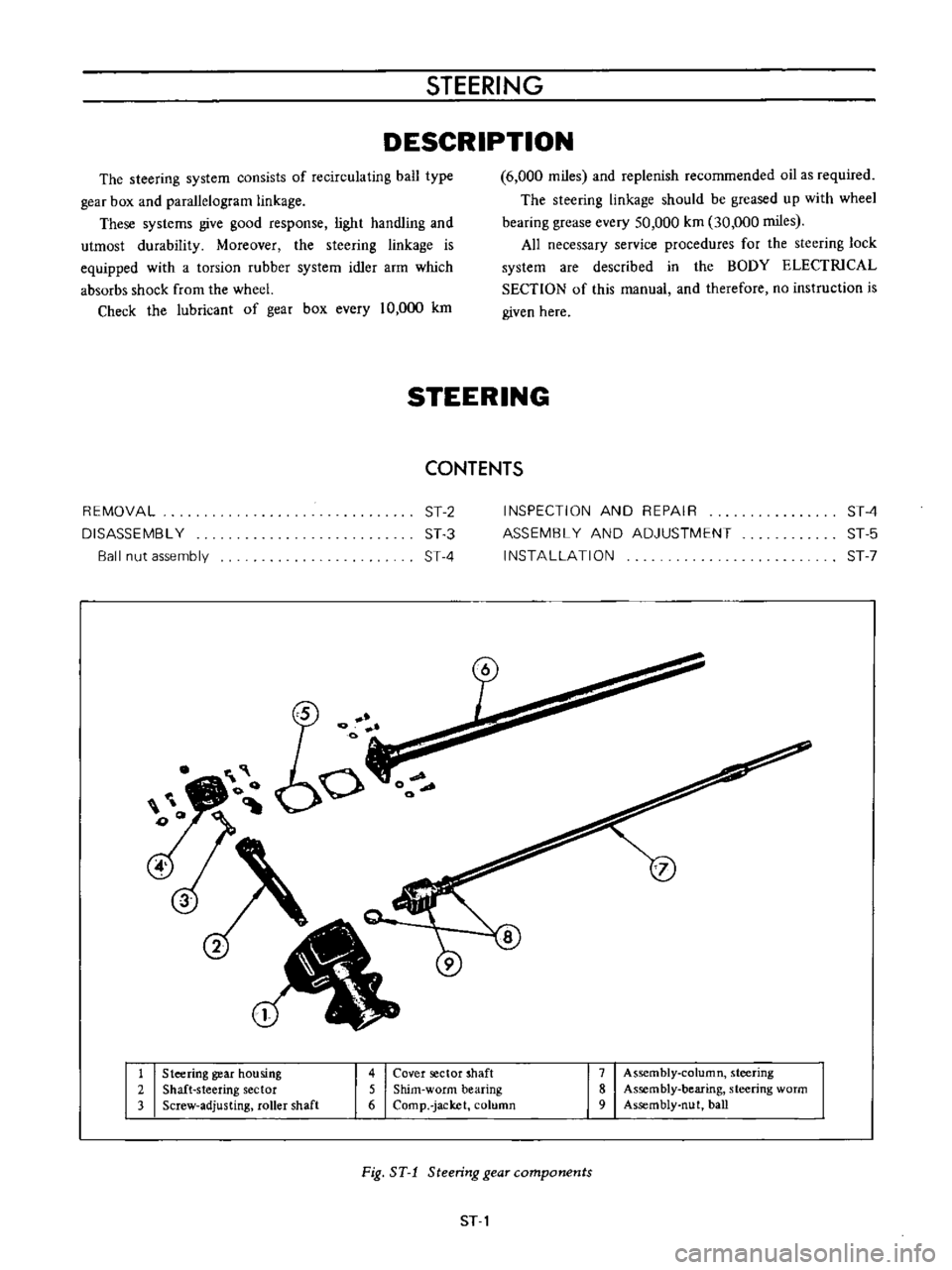
1
Steering
gear
housing
2
Shaft
steering
sector
3
Screw
adjusting
roller
shaft
4
Cover
sector
shaft
5
Shim
worm
bearing
6
Comp
jacket
column
7
Assembly
column
steering
8
Assembly
bearing
steering
worm
9
Assembly
nut
ball
Fig
ST
1
Steering
gear
components
ST
1
Page 162 of 513
Iii
I
o
t
I
I
CHASSIS
Fig
ST
2
Steering
wheel
REMOVAL
1
Remove
the
horn
ring
and
remove
the
steering
wheel
nut
and
pull
out
the
steering
wheel
by
the
use
of
a
Steer
ing
wheel
puller
ST27180000
3
Remove
the
turn
signal
and
lighting
switch
com
pletely
4
Remove
the
hand
lever
assembly
from
the
control
rod
assembly
by
unscrewing
the
fIxing
bolts
5
Remove
two
fIxing
bolts
used
to
secure
the
steering
column
to
the
instrument
panel
ST27180000
Fig
ST
3
Removing
steering
wheel
lock
nut
Note
The
horn
ring
can
be
easily
removed
by
two
bolts
2
Remove
the
steering
column
shell
Fig
ST
4
Removing
steering
column
upper
side
ST
2
Page 163 of 513

STEERING
6
Remove
six
bolts
used
to
secure
the
steering
column
hole
cover
to
the
dash
board
Fig
ST
5
Removing
steering
column
hole
cover
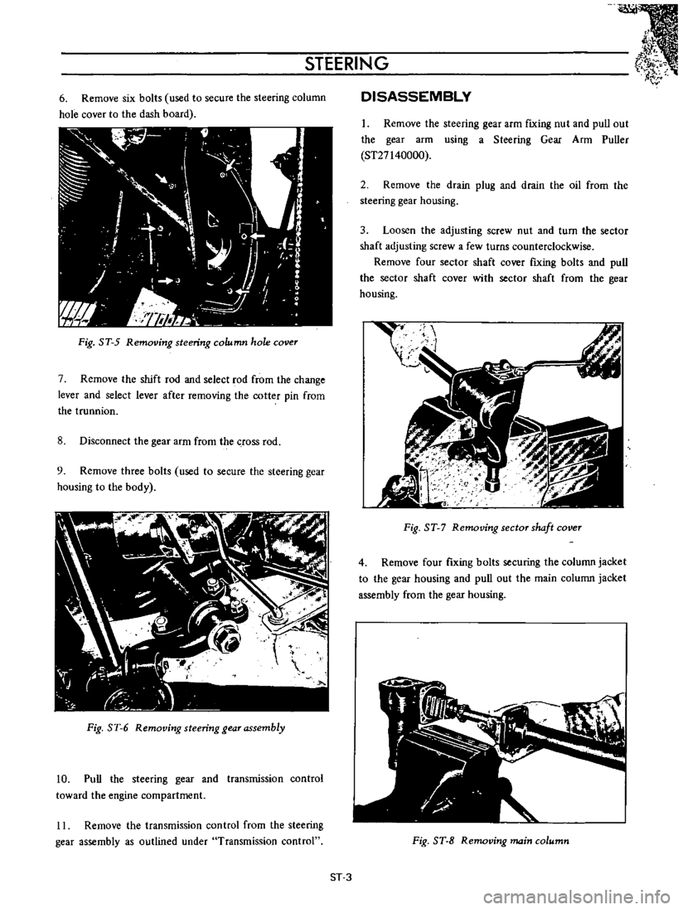
7
Remove
the
shift
rod
and
select
rod
from
the
change
lever
and
select
lever
after
removing
the
cotter
pin
from
the
trunnion
8
Disconnect
the
gear
arm
from
the
crOSS
rod
9
Remove
three
bolts
used
to
secure
the
steering
gear
housing
to
the
body
Fig
ST
6
Removing
steering
gear
assembly
10
Pull
the
steering
gear
and
transmission
control
toward
the
engine
compartment
11
Remove
the
transmission
control
from
the
steering
gear
assembly
as
outlined
under
Transmission
control
DISASSEMBLY
1
Remove
the
steering
gear
arm
fIxing
nut
and
pull
out
the
gear
arm
using
a
Steering
Gear
Arm
Puller
ST27140000
2
Remove
the
drain
plug
and
drain
the
oil
from
the
steering
gear
housing
3
Loosen
the
adjusting
screw
nut
and
turn
the
sector
shaft
adjusting
screw
a
few
turns
counterclockwise
Remove
four
sector
shaft
cover
fIxing
bolts
and
pull
the
sector
shaft
cover
with
sector
shaft
from
the
gear
housing
t
I
gJ
I
I
Fig
ST
7
Removing
sector
shaft
cover
4
Remove
four
fIxing
bolts
securing
the
column
jacket
to
the
gear
housing
and
pull
out
the
main
column
jacket
assembly
from
the
gear
housing
Fig
ST
8
Removing
main
column
ST
3
Page 164 of 513

CHASSIS
Note
Be
careful
not
to
allow
the
ball
nut
running
down
to
either
end
of
the
worm
The
ends
of
the
ball
guides
will
be
damaged
if
the
nut
is
allowed
to
rotate
until
stopped
at
the
end
of
the
worm
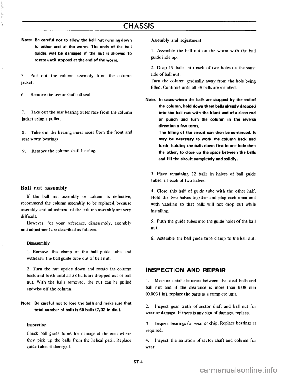
5
Pull
out
the
column
assembly
from
the
column
jacket
6
Remove
the
sector
shaft
oil
seal
7
Take
out
the
rear
bearing
outer
race
from
the
column
jacket
using
a
puller
8
Take
out
the
bearing
inner
races
from
the
front
and
rear
worm
bearings
9
Remove
the
column
shaft
bearing
Ball
nut
assembly
If
the
ball
nut
assembly
or
column
is
defective
recommend
the
column
assembly
to
be
replaced
because
assembly
and
adjustment
of
the
column
assembly
are
very
difficult
However
for
your
reference
disassembly
assembly
and
adjustment
are
described
as
follows
Disassembly
L
Remove
the
damp
of
the
ball
guide
lube
and
withdraw
the
ball
guide
tube
out
of
ball
nut
2
Turn
the
nut
upside
down
and
rotate
the
column
back
and
forth
until
all
38
balls
are
dropped
out
of
ball
nut
With
the
balls
removed
the
nul
can
be
pulled
endwise
off
the
column
Note
Be
careful
not
to
lose
the
balls
and
make
sure
that
total
number
of
balls
is
60
balls
7
32
in
dia
l
Inspection
Check
ball
guide
tubes
for
damage
at
the
ends
where
they
pick
up
the
balls
from
the
helical
path
Replace
guide
tubes
if
damaged
Assembly
and
adjustment
1
Assembie
the
ball
nut
on
the
worm
with
the
ball
guide
hole
up
2
Drop
19
balls
into
each
of
two
hoies
on
the
same
side
of
ball
nul
Turn
the
column
gradually
away
from
the
hole
being
filled
Continue
until
all
38
balls
are
installed
Note
I
n
cases
where
the
balls
are
stopped
by
the
end
of
the
column
hold
down
these
balls
already
dropped
into
the
ball
nut
with
the
blunt
end
of
a
clean
rod
or
punch
and
turn
the
column
in
the
reverse
direction
a
few
turns
The
filling
of
the
circuit
can
then
be
continued
It
may
be
o
ry
to
work
the
column
back
and
forth
holding
the
balls
down
first
in
one
hole
then
the
other
to
close
up
the
space
between
the
balls
and
fill
the
circuit
completely
and
solidly
3
Place
remammg
22
balls
in
halves
of
ball
guide
tubes
11
each
of
two
halves
4
Close
this
half
of
guide
tube
with
the
other
half
Hold
the
two
halves
together
and
plug
each
open
end
with
vaseline
so
that
balls
will
not
drop
out
while
installing
5
Push
the
guide
tubes
into
the
guide
holes
of
the
ball
nut
6
Assemble
the
ball
guide
tube
clamp
to
the
ball
nut
INSPECTION
AND
REPAIR
I
Measure
axial
clearance
between
the
steel
balls
and
ball
nut
and
if
the
clearance
is
more
than
0
08
mm
0
0031
in
replace
the
parts
as
a
complete
unit
2
Inspect
gear
teeth
of
sector
shaft
and
ball
nut
for
wear
or
damage
If
there
is
any
sign
of
damage
replace
3
Inspect
bearings
for
wear
or
chip
Replace
bearings
as
required
4
Inspect
the
serration
of
sector
shaft
and
colunm
for
wear
ST
4
Page 165 of 513
STEERING
ASSEMBLY
AND
AD
JUSTMENT
Tightening
torque
1
5
to
2
5
kg
m
110
8
to
18
1
ft
lb
II
1
r
I
II
U
J
Standard
shim
O
5mm
0
0197
in
1
Press
in
oil
seal
into
the
housing
Tightening
torque
1
7
to
2
8
kg
m
12
3
to
20
2
ft
Ib
Tightening
torque
2
0
to
3
0
kg
m
14
5
to
21
7
ft
Ib
Clearance
of
adjusting
screw
to
sector
shaft
0
05
mm
0
0020
in
L
Apply
grease
here
I
when
assembling
Pitman
arm
Tightening
torque
14kg
rn
101
ft
Ib
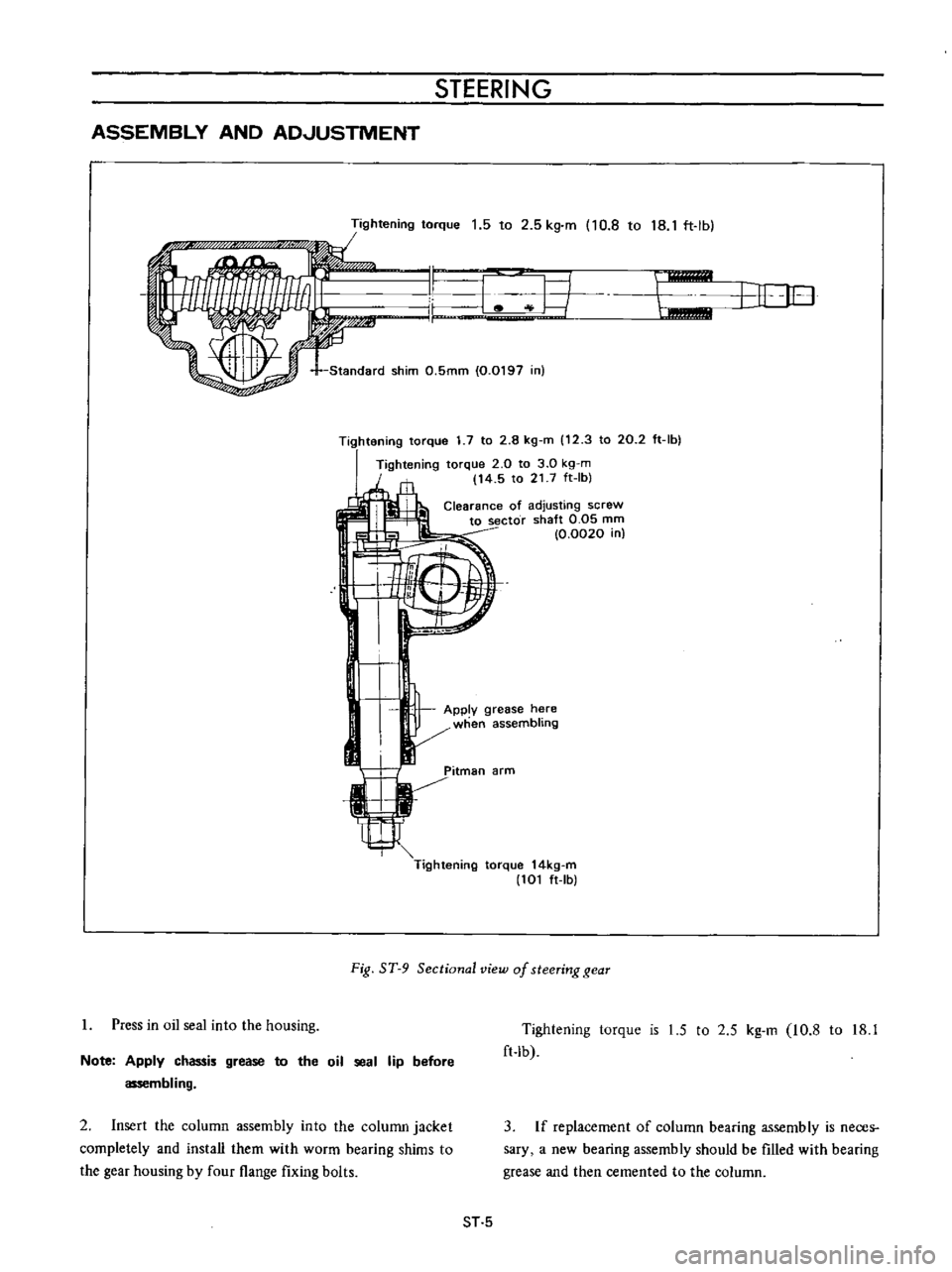
Fig
ST
9
Sectional
view
of
steering
gear
Note
Apply
chassis
grease
to
the
oil
seal
lip
before
assembling
2
Insert
the
column
assembly
into
the
column
jacket
completely
and
install
them
with
worm
bearing
shims
to
the
gear
housing
by
four
flange
fixing
bolts
Tightening
torque
is
1
5
to
2
5
kg
m
10
8
to
18
1
ft
lb
3
If
replacement
of
column
bearing
assembly
is
nece
r
sary
a
new
bearing
assembly
should
be
filled
with
bearing
grease
and
then
cemented
to
the
column
ST
5
Page 166 of 513

I
CHASSIS
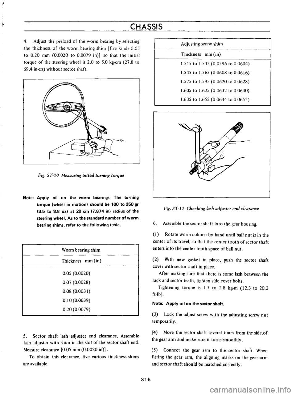
4
Adjust
the
preload
of
the
worm
bearing
by
selecting
the
thickness
of
he
worm
bearing
shim
five
kinds
0
05
to
0
20
mm
0
0020
to
0
0079
in
so
that
the
initial
torque
of
the
steering
wheel
is
2
0
to
5
0
kg
cm
27
8
to
694
in
oz
without
sector
shaft
J
Fig
ST
10
Measuring
initial
tunring
torque
Note
Apply
oil
on
the
worm
bearings
The
turning
torque
wheel
in
motion
should
be
100
to
250
gr
13
5
to
8
8
oz
at
20
em
7
874
in
radius
of
the
steering
wheel
As
to
the
standard
number
of
worm
bearing
shims
refer
to
the
following
table
Worm
bearing
shim
Thickness
mm
in
0
05
0
0020
0
07
0
0028
0
08
0
0031
0
10
0
0039
0
20
0
0079
5
Sector
shaft
lash
adjuster
end
clearance
Assemble
lash
adjuster
with
shim
in
the
slot
of
the
sector
shaft
end
Measure
clearance
0
05
mm
0
0020
in
To
obtain
this
clearance
five
various
thickness
shims
are
available
Adjusting
screw
shim
Thickness
mm
in
1
515
to
1
535
0
0596
to
0
0604
1
545
to
1
565
0
0608
to
0
0616
1
575
to
1
595
0
0620
to
0
0628
1
605
to
1
625
0
0632
to
0
0640
1
63510
1
655
0
0644
to
0
0652
Fig
ST
J
J
Checking
lash
adjuster
end
clearance
6
Assemble
the
sector
shaft
into
the
gear
housing
I
Rotate
worm
column
by
hand
unlil
ball
nut
is
in
the
center
of
its
travel
so
that
the
center
tooth
of
sector
shaft
enters
into
the
center
tooth
space
of
ball
nut
2
With
new
gasket
in
place
push
the
sector
shaft
cover
with
sector
shaft
in
place
After
making
sure
that
there
is
some
lash
between
the
rack
and
sector
teeth
tighten
side
cover
bolts
Tightening
torque
is
I
7
to
2
8
kg
m
I2
3
to
20
2
ft
lb
Note
Apply
oil
on
the
sector
shaft
3
Lock
the
adjust
screw
with
the
adjusting
screw
nut
temporarily
4
Move
the
sector
shaft
several
times
from
the
side
of
the
gear
arm
and
make
sure
it
turns
smoothly
5
Connect
the
gear
arm
to
the
sector
shaft
When
fitting
the
gear
arm
the
aligning
marks
on
the
gear
arm
and
sector
shaft
should
be
matched
correctly
ST
6
Page 167 of 513
STEERING
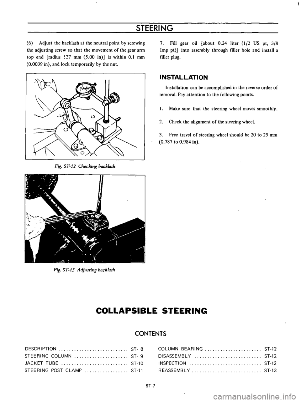
6
Adjust
the
backlash
at
the
neutral
point
by
screwing
the
adjusting
screw
so
that
the
movement
of
the
gear
arm
top
end
radius
7
mm
5
00
in
is
within
0
1
mm
0
0039
in
and
lock
temporarily
by
the
nut
Fig
ST
12
Checking
backlash
Fig
ST
13
Adjusting
backlash
7
Fill
gear
oil
about
0
24
liter
I
2
US
pt
3
8
Imp
pt
into
assembly
through
f1ller
hole
and
install
a
mIer
plug
INSTALLATION
Installation
can
be
accomplished
in
the
reverse
order
of
removal
Pay
attention
to
the
following
points
I
Make
sure
that
the
steering
wheel
moves
smoothly
2
Check
the
alignment
of
the
steering
wheeL
3
Free
travel
of
steering
wheel
should
be
20
to
25
mm
0
787
to
0
984
in
COLLAPSIBLE
STEERING
CONTENTS
DESCRIPTION
STEERING
COLUMN
JACKET
TUBE
STEERING
POST
CLAMP
ST
8
ST
9
ST
10
ST
11
COLUMN
BEARING
DISASSEMBL
Y
INSPECTION
REASSEMBL
Y
ST
12
ST
12
ST
12
ST
13
ST
7
Page 168 of 513

CHASSIS
I
l
I
I
2
fa
r
o
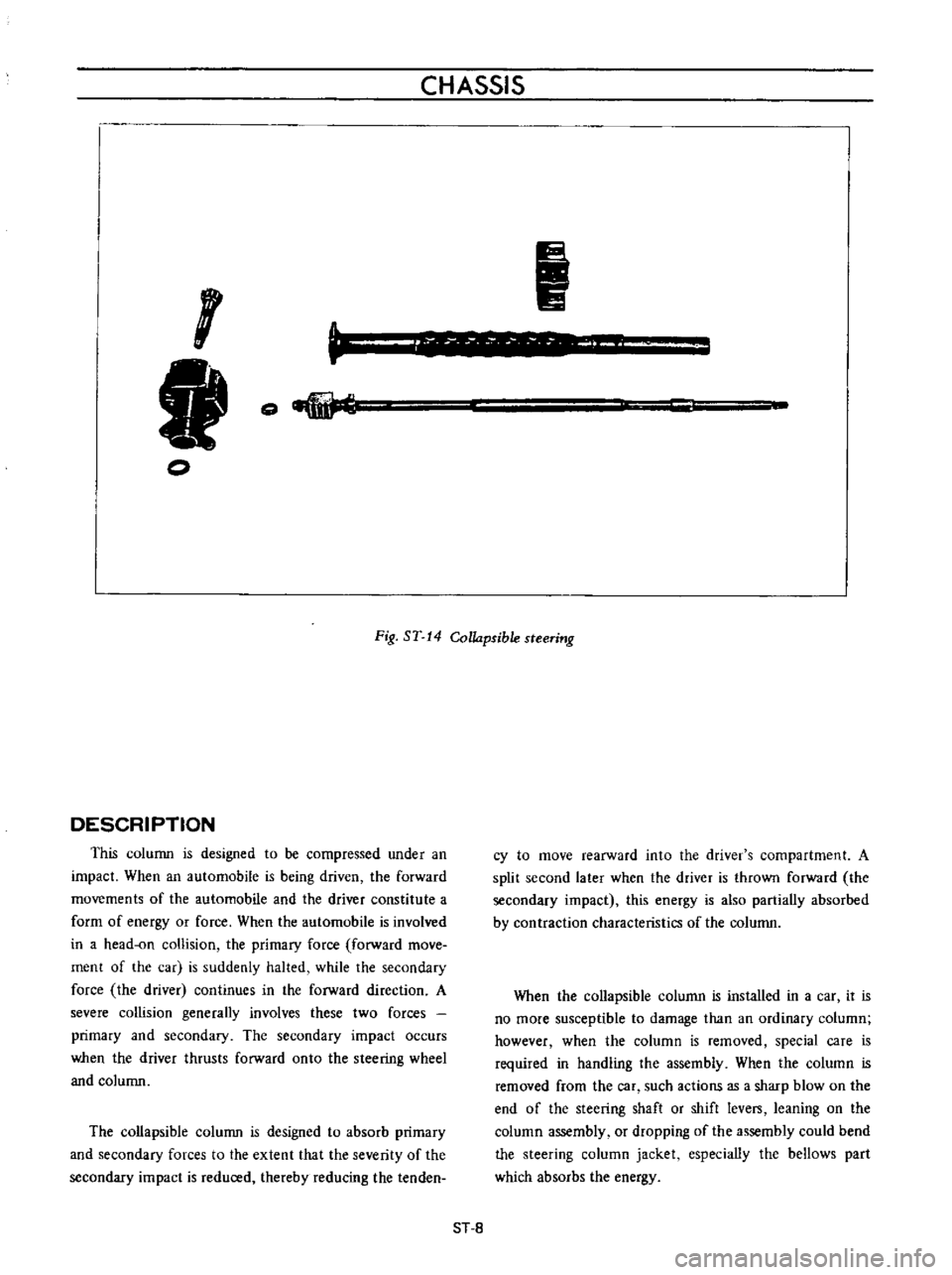
Fig
ST
14
Collapsible
steering
DESCRIPTION
This
column
is
designed
to
be
compressed
under
an
impact
When
an
automobile
is
being
driven
the
forward
movements
of
the
automobile
and
the
driver
constitute
a
form
of
energy
or
force
When
the
automobile
is
involved
in
a
head
on
collision
the
primary
force
forward
move
ment
of
the
car
is
suddenly
halted
while
the
secondary
force
the
driver
continues
in
the
forward
direction
A
severe
collision
generally
involves
these
two
forces
primary
and
secondary
The
secondary
impact
occurs
when
the
driver
thrusts
forward
onto
the
steering
wheel
and
column
The
collapsible
column
is
designed
to
absorb
primary
and
secondary
forces
to
the
extent
that
the
severity
of
the
secondary
impact
is
reduced
thereby
reducing
the
tenden
cy
to
move
rearward
into
the
driver
s
compartment
A
split
second
later
when
the
driver
is
thrown
forward
the
secondary
impact
this
energy
is
also
partially
absorbed
by
contraction
characteristics
of
the
column
When
the
collapsible
column
is
installed
in
a
car
it
is
no
more
susceptible
to
damage
than
an
ordinary
column
however
when
the
column
is
removed
special
care
is
required
in
handling
the
assembly
When
the
column
is
removed
from
the
car
such
actions
as
a
sharp
blow
on
the
end
of
the
steering
shaft
or
shift
levers
leaning
on
the
column
assembly
or
dropping
of
the
assembly
could
bend
the
steering
column
jacket
especially
the
bellows
part
which
absorbs
the
energy
ST
8