Page 297 of 900

INSP
ADJ
3 - 90
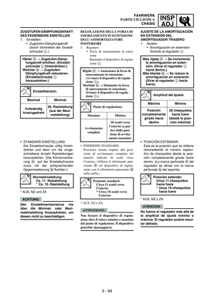
DRUCKSTUFEN-DÄMPFUNGS-
KRAFT DER TELESKOPGABEL
EINSTELLEN
1. Demontieren:
Gummikappe
2. Einstellen:
Druckstufen-Dämpfungskraft
(durch Verdrehen der Einstell-
schraube
1)
STANDARD-EINSTELLUNG:
Die Einstellschraube völlig hinein-
drehen und dann um die vorge-
schriebene Anzahl Raststellungen
herausdrehen.
* EUROPE
** AUS, NZ und ZA
ACHTUNG:
Den Einstellmechanismus nie
über die Minimal- oder Maxi-
maleinstellung hinausdrehen, um
diesen nicht zu beschädigen.
WARNUNG
Sicherstellen, dass beide Gabel-
beine gleichmäßig eingestellt
sind. Eine ungleichmäßige Ein-
stellung beeinträchtigt das Fahr-
verhalten.
3. Montieren:
Gummikappe Härter a → Druckstufen-Dämp-
fungskraft erhöhen. (Einstell-
schraube 1 hineindrehen.)
Weicher b → Druckstufen-
Dämpfungskraft reduzieren.
(Einstellschraube 1 heraus-
drehen.)
Einstellbereich:
Maximal Minimal
Vollständig
hineingedreht20. Raststellung
(aus der Maxi-
malstellung)
Normaleinstellung:
8. Raststellung
* 10. Raststellung
** 12. Raststellung
REGOLAZIONE DELLA FORZA DI
SMORZAMENTO IN COMPRES-
SIONE DELLA FORCELLA ANTE-
RIORE
1. Togliere:
Coperchio in gomma
2. Regolare:
Forza di smorzamento in com-
pressione
Ruotando il dispositivo di regola-
zione 1.
POSIZIONE STANDARD:
Posizione ritratta rispetto alla posi-
zione di avvitamento completo del
numero indicato di scatti verso
l’esterno.
* EUROPE
** AUS, NZ e ZA
ATTENZIONE:
Non forzare il dispositivo di regola-
zione oltre il valore minimo o massimo
del punto di regolazione. Il dispositivo
potrebbe danneggiarsi.
AVVERTENZA
Regolare sempre allo stesso modo ogni
forcella anteriore. Una regolazione
disuguale può determinare difficoltà
di manovrabilità e perdita di stabilità.
3. Installare:
Coperchio in gomma Rigido a → Aumentare la forza di
smorzamento in compressione.
(Avvitare il dispositivo di
regolazione 1.)
Morbido b → Diminuire la forza
di smorzamento in compres-
sione. (Svitare il dispositivo di
regolazione 1.)
Punto di regolazione:
Massimo Minimo
Avvitamento
completo20 scatti verso
l’esterno (a par-
tire dalla posi-
zione di avvita-
mento massimo)
Posizione standard:
8 scatti verso l’esterno
* 10 scatti verso l’esterno
** 12 scatti verso l’esterno
AJUSTE DE LA AMORTIGUACIÓN
EN COMPRESIÓN DE LA
HORQUILLA DELANTERA
1. Extraer:
Tapa de goma
2. Ajustar:
Amortiguación en compresión
Girando el regulador
1.
POSICIÓN ESTÁNDAR:
Esta es la posición que se obtiene
retrocediendo el número especí-
fico de chasquidos desde la posi-
ción completamente girada hacia
dentro.
* EUROPE
** AUS, NZ y ZA
ATENCION:
No fuerce el regulador más allá de
la amplitud de ajuste mínima o
máxima. El regulador podría resul-
tar dañado.
ADVERTENCIA
Ajuste siempre las dos barras de
la horquilla a la misma posición.
Un ajuste desequilibrado puede
reducir la maniobrabilidad y la
estabilidad.
3. Instalar:
Tapa de goma Más rígida a → Se incrementa
la amortiguación en compre-
sión. (Girar el regulador 1
hacia dentro.)
Más blanda b → Se reduce la
amortiguación en compre-
sión. Girar el regulador 1
hacia fuera.)
Amplitud del ajuste:
Máxima Mínima
Posición
completamente
girado hacia
dentro20 chasquidos
hacia fuera
(desde la posi-
ción máxima)
Posición estándar:
8 chasquidos hacia
fuera
* 10 chasquidos hacia
fuera
** 12 chasquidos hacia
fuera
FAHRWERK
PARTE CICLISTICA
CHASIS
Page 298 of 900

3 - 91
INSP
ADJ
EC36K000REAR SHOCK ABSORBER
INSPECTION
1. Inspect:
Swingarm smooth action
Abnormal noise/unsmooth
action
→ Grease the pivoting
points or repair the pivoting
points.
Damage/oil leakage
→
Replace.
REAR SHOCK ABSORBER
SPRING PRELOAD ADJUSTMENT
1. Elevate the rear wheel by plac-
ing the suitable stand under the
engine.
2. Remove:
Rear frame
3. Loosen:
Locknut
1
4. Adjust:
Spring preload
By turning the adjuster
2.
* For EUROPE
** For AUS, NZ and ZA
NOTE:Be sure to remove all dirt and mud
from around the locknut and
adjuster before adjustment.
The length of the spring (installed)
changes 1.5 mm (0.06 in) per turn
of the adjuster.
CAUTION:
Never attempt to turn the adjuster
beyond the maximum or mini-
mum setting.
5. Tighten:
Locknut
6. Install:
Rear frame (upper)
Rear frame (lower) Stiffer → Increase the spring
preload. (Turn the adjuster 2
in.)
Softer → Decrease the spring
preload. (Turn the adjuster 2
out.)
Spring length (installed)
a:
Standard lengthExtent of
adjustment
248 mm (9.76 in)
* 246 mm
(9.69 in)
** 247.5 mm
(9.74 in)237.5 ~
258.5 mm
(9.35 ~ 10.18 in)
T R..32 Nm (3.2 m · kg, 23 ft · lb)
T R..29 Nm (2.9 m · kg, 21 ft · lb)
CONTROLE DE L’AMORTISSEUR
ARRIÈRE
1. Contrôler:
Fonctionnement régulier du bras
oscillant
Bruit anormal/fonctionnement
irrégulier → Graisser ou réparer
les points de pivot.
Endommagement/fuite d’huile →
Remplacer.
REGLAGE DE LA PRECON-
TRAINTE DU RESSORT DE
L’AMORTISSEUR ARRIERE
1. Surélever la roue arrière en plaçant
un support adéquat sous le moteur.
2. Déposer:
Cadre arrière
3. Desserrer:
Contre-écrou 1
4. Régler:
Précontrainte de ressort
En vissant le dispositif de réglage
2.
* EUROPE
** AUS, NZ et ZA
N.B.:
Avant d’effectuer le réglage, bien
enlever toute la boue et toutes les sale-
tés autour du contre-écrou et du dispo-
sitif de réglage.
La longueur du ressort (monté) change
de 1,5 mm (0,06 in) par tour du dispo-
sitif de réglage.
ATTENTION:
Ne jamais forcer le dispositif de
réglage au-delà des limites maximum
ou minimum.
5. Serrer:
Contre-écrou
6. Monter:
Cadre arrière (supérieur)
Cadre arrière (inférieur) Plus dur → Augmenter la
précontrainte du ressort. (Visser
le dispositif de réglage 2.)
Plus mou → Diminuer la précon-
trainte du ressort. (Dévisser le
dispositif de réglage 2.)
Longueur du ressort
(monté) a:
Longueur
standardPlage de réglage
248 mm (9,76 in)
* 246 mm
(9,69 in)
** 247,5 mm
(9,74 in)237,5 à 258,5 mm
(9,35 à 10,18 in)
T R..32 Nm (3,2 m · kg, 23 ft · lb)
T R..29 Nm (2,9 m · kg, 21 ft · lb)
CHASSIS
CHASSIS
Page 299 of 900

INSP
ADJ
3 - 92
FEDERBEIN KONTROLLIEREN
1. Kontrollieren:
Leichtgängigkeit der Schwinge
Geräuschvoll/stockend
→
Drehpunkte schmieren, ggf.
instand setzen.
Beschädigt/undicht
→ Erneu-
ern.
FEDERVORSPANNUNG DES
FEDERBEINS EINSTELLEN
1. Das Motorrad aufbocken, um
das Hinterrad vom Boden abzu-
heben.
2. Demontieren:
Rahmenheck
3. Lockern:
Sicherungsmutter
1
4. Einstellen:
Federvorspannung
(durch Verdrehen des Feder-
vorspannrings
2)
* EUROPE
** AUS, NZ und ZA
HINWEIS:
Vor der Einstellung die Ringe von
jeglichem Schmutz und Schlamm
befreien.
Die Einbaulänge der Feder ändert
sich um 1,5 mm (0,06 in) pro
Umdrehung des Federvorspann-
rings.
ACHTUNG:
Den Einstellmechanismus nie
über die Maximal- oder Mini-
maleinstellung hinausdrehen.
5. Festziehen:
Sicherungsmutter
6. Montieren:
Rahmenheck (oben)
Rahmenheck (unten) Härter → Federvorspannung
erhöhen. (Federvorspannring
2 hineindrehen.)
Weicher → Federvorspannung
reduzieren. (Federvorspann-
ring 2 herausdrehen.)
Einbaulänge a der
Feder:
Standardlänge Einstellbereich
248 mm (9,76 in)
* 246 mm
(9,69 in)
** 247,5 mm
(9,74 in)237,5–258,5 mm
(9,35–10,18 in)
T R..32 Nm (3,2 m · kg, 23 ft · lb)
T R..29 Nm (2,9 m · kg, 21 ft · lb)
CONTROLLO AMMORTIZZA-
TORE POSTERIORE
1. Controllare:
Funzionamento uniforme del for-
cellone oscillante
Rumorosità inusuale/funziona-
mento non uniforme → Lubrificare
o riparare i punti di articolazione.
Danno/perdita di olio → Sostituire.
REGOLAZIONE PRECARICO
DELLA MOLLA DELL’AMMOR-
TIZZATORE POSTERIORE
1. Sollevare la ruota posteriore ponendo
un apposito cavalletto sotto il motore.
2. Togliere:
Telaio posteriore
3. Allentare:
Controdado 1
4. Regolare:
Precarico della molla
Ruotando il dispositivo di regola-
zione 2.
* EUROPE
** AUS, NZ e ZA
NOTA:
Prima di procedere alla regolazione,
assicurarsi di eliminare tutta la sporci-
zia e il fango intorno al controdado e
al dispositivo di regolazione.
La lunghezza della molla (installata)
varia di 1,5 mm (0,06 in) per ogni rota-
zione del dispositivo di regolazione.
ATTENZIONE:
Non tentare mai di ruotare il disposi-
tivo oltre il livello di regolazione
minimo e massimo.
5. Serrare:
Controdado
6. Installare:
Telaio posteriore (superiore)
Telaio posteriore (inferiore) Rigido → Aumentare il precarico
della molla. (Avvitare il
dispositivo di regolazione 2.)
Morbido → Diminuire il precarico
della molla. (Svitare il dispositivo
di regolazione 2.)
Lunghezza della molla
(installata) a:
Lunghezza
standardPunto di
regolazione
248 mm (9,76 in)
* 246 mm
(9,69 in)
** 247,5 mm
(9,74 in)237,5 ~ 258,5 mm
(9,35 ~ 10,18 in)
T R..32 Nm (3,2 m · kg, 23 ft · lb)
T R..29 Nm (2,9 m · kg, 21 ft · lb)
COMPROBACIÓN DEL
AMORTIGUADOR TRASERO
1. Comprobar:
Suavidad de movimiento del
basculante
Ruido anómalo/movimiento
irregular
→ Engrase los pun-
tos de pivote o repárelos.
Dañado/fugas
→ Cambiar.
AJUSTE DE LA PRECARGA DEL
MUELLE DEL AMORTIGUADOR
TRASERO
1. Eleve la rueda trasera colocando
un soporte adecuado debajo del
motor.
2. Extraer:
Bastidor trasero
3. Aflojar:
Contratuerca
1
4. Ajustar:
Precarga del muelle
Girando el regulador
2.
* EUROPE
** AUS, NZ y ZA
NOTA:
Antes de proceder al ajuste eli-
mine toda la suciedad y el barro en
torno a la contratuerca y el regula-
dor.
La longitud del muelle (montada)
varía 1,5 mm (0,06 in) por cada
vuelta del regulador.
ATENCION:
No gire nunca el regulador más
allá del límite máximo o mínimo.
5. Apretar:
Contratuerca
6. Instalar:
Bastidor trasero (superior)
Bastidor trasero (inferior) Más rígido → Se incrementa la
precarga del muelle. (Girar el
regulador 2 hacia dentro.)
Más blando → Se reduce la
precarga del muelle. (Girar el
regulador 2 hacia fuera.)
Longitud del muelle
(montada) a:
Longitud
estándarAmplitud del
ajuste
248 mm (9,76 in)
* 246 mm
(9,69 in)
** 247,5 mm
(9,74 in)237,5 ~
258,5 mm
(9,35 ~ 10,18 in)
T R..32 Nm (3,2 m · kg, 23 ft · lb)
T R..29 Nm (2,9 m · kg, 21 ft · lb)
FAHRWERK
PARTE CICLISTICA
CHASIS
Page 300 of 900

3 - 93
INSP
ADJ
EC36N014REAR SHOCK ABSORBER
REBOUND DAMPING FORCE
ADJUSTMENT
1. Adjust:
Rebound damping force
By turning the adjuster
1.
Stiffer a → Increase the
rebound damping force.
(Turn the adjuster 1 in.)
Softer b → Decrease the
rebound damping force.
(Turn the adjuster 1 out.)
Extent of adjustment:
Maximum Minimum
Fully turned in
position20 clicks out
(from maximum
position)
STANDARD POSITION:
This is the position which is back
by the specific number of clicks
from the fully turned-in position.
(Which align the punch mark
a on
the adjuster with the punch mark
b on the bracket.)
* For AUS, NZ and ZA
CAUTION:
Do not force the adjuster past the
minimum or maximum extent of
adjustment. The adjuster may be
damaged.
Standard position:
About 11 clicks out
* About 10 clicks out
REGLAGE DE LA FORCE
D’AMORTISSEMENT A LA
DETENTE DE L’AMORTISSEUR
ARRIERE
1. Régler:
Force d’amortissement à la
détente
En tournant le dispositif de
réglage 1.
Plus dur a → Augmenter la force
d’amortissement à la détente.
(Visser le dispositif de réglage 1.)
Plus mou b → Diminuer la force
d’amortissement à la détente.
(Dévisser le dispositif de réglage
1.)
Plage de réglage:
Maximum Minimum
Position
complètement
visséedévissé de
20 déclics (par
rapport à la posi-
tion maximum)
POSITION STANDARD:
Position à laquelle le dispositif de
réglage est dévissé du nombre de tours
spécifié par rapport à la position com-
plètement vissée. (Ce qui aligne le
repère a du dispositif de réglage avec
le repère b du support.)
* AUS, NZ et ZA
ATTENTION:
Ne pas forcer le dispositif de réglage
au-delà des positions minimum ou
maximum. Cela pourrait l’endomma-
ger.
Position standard:
Dévissé d’environ 11
déclics
*Dévissé d’environ 10
déclics
CHASSIS
CHASSIS
Page 301 of 900

INSP
ADJ
3 - 94
ZUGSTUFEN-DÄMPFUNGSKRAFT
DES FEDERBEINS EINSTELLEN
1. Einstellen:
Zugstufen-Dämpfungskraft
(durch Verdrehen der Einstell-
schraube
1.)
Härter a → Zugstufen-Dämp-
fungskraft erhöhen. (Einstell-
schraube 1 hineindrehen.)
Weicher b → Zugstufen-
Dämpfungskraft reduzieren.
(Einstellschraube 1
herausdrehen.)
Einstellbereich:
Maximal Minimal
Vollständig
hineingedreht20. Raststellung
(aus der Maxi-
malstellung)
STANDARD-EINSTELLUNG:
Die Einstellschraube völlig hinein-
drehen und dann um die vorge-
schriebene Anzahl Raststellungen
herausdrehen. (Die Körnermarkie-
rung
a auf der Einstellschraube
muss mit der entsprechenden
Gegenmarkierung
b fluchten.)
* AUS, NZ und ZA
ACHTUNG:
Den Einstellmechanismus nie
über die Minimal- oder Maxi-
maleinstellung hinausdrehen, um
diesen nicht zu beschädigen.
Normaleinstellung:
Ca. 11. Raststellung
* Ca. 10. Raststellung
REGOLAZIONE DELLA FORZA DI
SMORZAMENTO IN ESTENSIONE
DELL’AMMORTIZZATORE
POSTERIORE
1. Regolare:
Forza di smorzamento in esten-
sione
Ruotando il dispositivo di regola-
zione 1.
POSIZIONE STANDARD:
Posizione ritratta rispetto alla posi-
zione di avvitamento completo del
numero indicato di scatti verso
l’esterno. (Allinea il riferimento pun-
zonato a sul dispositivo di regola-
zione con il riferimento punzonato b
sulla staffa.)
* AUS, NZ e ZA
ATTENZIONE:
Non forzare il dispositivo di regola-
zione oltre il valore minimo o massimo
del punto di regolazione. Il dispositivo
potrebbe danneggiarsi. Rigido a → Aumentare la forza di
smorzamento in estensione.
(Avvitare il dispositivo di regola-
zione 1.)
Morbido b → Diminuire la forza
di smorzamento in estensione.
(Svitare il dispositivo di regola-
zione 1.)
Punto di regolazione:
Massimo Minimo
Avvitamento
completo20 scatti verso
l’esterno (a par-
tire dalla posi-
zione di avvita-
mento massimo)
Posizione standard:
Circa 11 scatti verso
l’esterno
* Circa 10 scatti verso
l’esterno
AJUSTE DE LA AMORTIGUACIÓN
EN EXTENSIÓN DEL
AMORTIGUADOR TRASERO
1. Ajustar:
Amortiguación en extensión
Girando el regulador
1.
Más rígida a → Se incrementa
la amortiguación en exten-
sión. (Girar el regulador 1
hacia dentro.)
Más blanda b → Se reduce la
amortiguación en extensión.
(Girar el regulador 1 hacia
fuera).
Amplitud del ajuste:
Máxima Mínima
Posición
completamente
girado hacia
dentro20 chasquidos
hacia fuera
(desde la posi-
ción máxima)
POSICIÓN ESTÁNDAR:
Esta es la posición que se obtiene
retrocediendo el número especí-
fico de chasquidos desde la posi-
ción completamente girada hacia
dentro. (La marca perforada
a del
regulador se alinea con la marca
perforada
b del soporte).
* AUS, NZ y ZA
ATENCION:
No fuerce el regulador más allá de
la amplitud de ajuste mínima o
máxima. El regulador podría resul-
tar dañado.
Posición estándar:
Unos 11 chasquidos
hacia fuera
* Unos 10 chasquidos
hacia fuera
FAHRWERK
PARTE CICLISTICA
CHASIS
Page 302 of 900

3 - 95
INSP
ADJ
EC36c000REAR SHOCK ABSORBER LOW
COMPRESSION DAMPING FORCE
ADJUSTMENT
1. Adjust:
Low compression damping
force
By turning the adjuster
1.
Stiffer a → Increase the low
compression damping force.
(Turn the adjuster 1 in.)
Softer b → Decrease the low
compression damping force.
(Turn the adjuster 1 out.)
Extent of adjustment:
Maximum Minimum
Fully turned in
position20 clicks out
(from maximum
position)
1b
a
STANDARD POSITION:
This is the position which is back
by the specific number of clicks
from the fully turned-in position.
(Which align the punch mark
a on
the adjuster with the punch mark
b on the high compression damp-
ing adjuster.)
* For EUROPE
** For AUS, NZ and ZA
CAUTION:
Do not force the adjuster past the
minimum or maximum extent of
adjustment. The adjuster may be
damaged.
Standard position:
About 11 clicks out
* About 10 clicks out
** About 8 clicks out
a
b
REGLAGE DE LA FORCE
D’AMORTISSEMENT A LA
COMPRESSION BASSE DE
L’AMORTISSEUR ARRIERE
1. Régler:
Force d’amortissement à la com-
pression basse
En tournant le dispositif de
réglage 1.
Plus dur a → Augmenter la force
d’amortissement à la
compression basse. (Visser le
dispositif de réglage 1.)
Plus mou b → Diminuer la force
d’amortissement. (Dévisser le
dispositif de réglage 1.)
Plage de réglage:
Maximum Minimum
Position
complètement
visséedévissé de
20 déclics (par
rapport à la posi-
tion maximum)
POSITION STANDARD:
Position à laquelle le dispositif de
réglage est dévissé du nombre de tours
spécifié par rapport à la position com-
plètement vissée. (Ce qui aligne le
repère a du dispositif de réglage avec
le repère b du dispositif de réglage de
l’amortissement à la compression
haute.)
* EUROPE
** AUS, NZ et ZA
ATTENTION:
Ne pas forcer le dispositif de réglage
au-delà des positions minimum ou
maximum. Cela pourrait l’endomma-
ger.
Position standard:
Dévissé d’environ 11
déclics
*Dévissé d’environ 10
déclics
** Dévissé d’environ 8
déclics
CHASSIS
CHASSIS
Page 303 of 900

INSP
ADJ
3 - 96
UNTERE DRUCKSTUFEN-
DÄMPFUNGSKRAFT DES
FEDERBEINS EINSTELLEN
1. Einstellen:
untere Druckstufen-Dämp-
fungskraft
(durch Verdrehen der Einstell-
schraube
1.)
Härter a → Untere Druckstu-
fen-Dämpfungskraft erhö-
hen. (Einstellschraube 1
hineindrehen.)
Weicher b → Untere Druckstu-
fen-Dämpfungskraft reduzie-
ren. (Einstellschraube 1
herausdrehen.)
Einstellbereich:
Maximal Minimal
Vollständig
hineingedreht20. Raststellung
(aus der Maxi-
malstellung)
STANDARD-EINSTELLUNG:
Die Einstellschraube völlig hinein-
drehen und dann um die vorge-
schriebene Anzahl Raststellungen
herausdrehen. (Die Körnermarkie-
rung
a auf der Einstellschraube
muss mit der entsprechenden
Gegenmarkierung
b fluchten.)
* EUROPE
** AUS, NZ und ZA
ACHTUNG:
Den Einstellmechanismus nie
über die Minimal- oder Maxi-
maleinstellung hinausdrehen, um
diesen nicht zu beschädigen.
Normaleinstellung:
Ca. 11. Raststellung
* Ca. 10. Raststellung
** Ca. 8. Raststellung
REGOLAZIONE DELLA FORZA DI
SMORZAMENTO IN BASSA COM-
PRESSIONE DELL’AMMORTIZ-
ZATORE POSTERIORE
1. Regolare:
Forza di smorzamento in bassa
compressione
Ruotando il dispositivo di regola-
zione 1.
POSIZIONE STANDARD:
Posizione ritratta rispetto alla posi-
zione di avvitamento completo del
numero indicato di scatti verso
l’esterno. (Allinea il riferimento pun-
zonato a sul dispositivo di regola-
zione con il riferimento punzonato b
sul dispositivo di regolazione di smor-
zamento in alta compressione.)
* EUROPE
** AUS, NZ e ZA
ATTENZIONE:
Non forzare il dispositivo di regola-
zione oltre il valore minimo o massimo
del punto di regolazione. Il dispositivo
potrebbe danneggiarsi. Rigido a → Aumentare la forza di
smorzamento in bassa
compressione. (Avvitare il
dispositivo di regolazione 1.)
Morbido b → Diminuire la forza
di smorzamento in bassa
compressione. (Svitare il
dispositivo di regolazione 1.)
Punto di regolazione:
Massimo Minimo
Avvitamento
completo20 scatti verso
l’esterno (a par-
tire dalla posi-
zione di avvita-
mento massimo)
Posizione standard:
Circa 11 scatti verso
l’esterno
* Circa 10 scatti verso
l’esterno
** Circa 8 scatti verso
l’esterno
AJUSTE DE LA AMORTIGUACIÓN
EN COMPRESIÓN BAJA DEL
AMORTIGUADOR TRASERO
1. Ajustar:
Amortiguación en compresión
baja
Girando el regulador
1.
Más rígida a → Se incrementa
la amortiguación en
compresión baja. (Girar el
regulador 1 hacia dentro.)
Más blanda b → Se reduce la
amortiguación en compre-
sión baja. (Girar el regulador
1 hacia fuera.)
Amplitud del ajuste:
Máxima Mínima
Posición
completamente
girado hacia
dentro20 chasquidos
hacia fuera
(desde la posi-
ción máxima)
POSICIÓN ESTÁNDAR:
Esta es la posición que se obtiene
retrocediendo el número especí-
fico de chasquidos desde la posi-
ción completamente girada hacia
dentro. (La marca perforada
a del
regulador se alinea con la marca
perforada
b del regulador de
amortiguación en compresión
alta).
* EUROPE
** AUS, NZ y ZA
ATENCION:
No fuerce el regulador más allá de
la amplitud de ajuste mínima o
máxima. El regulador podría resul-
tar dañado.
Posición estándar:
Unos 11 chasquidos
hacia fuera
* Unos 10 chasquidos
hacia fuera
** Unos 8 chasquidos
hacia fuera
FAHRWERK
PARTE CICLISTICA
CHASIS
Page 304 of 900

3 - 97
INSP
ADJ
EC36d000REAR SHOCK ABSORBER HIGH
COMPRESSION DAMPING FORCE
ADJUSTMENT
1. Adjust:
High compression damping
force
By turning the adjuster
1.
Stiffer a → Increase the high
compression damping force.
(Turn the adjuster 1 in.)
Softer b → Decrease the high
compression damping force.
(Turn the adjuster 1 out.)
Extent of adjustment:
Maximum Minimum
Fully turned in
position2 turns out
(from maximum
position)
1ba
STANDARD POSITION:
This is the position which is back
by the specific number of turns
from the fully turned-in position.
(Which align the punch mark
a on
the adjuster with the punch mark
b on the adjuster body.)
* For AUS, NZ and ZA
CAUTION:
Do not force the adjuster past the
minimum or maximum extent of
adjustment. The adjuster may be
damaged.
Standard position:
About 1-1/4 turns out
* About 1-1/2 turns out
a
b
REGLAGE DE LA FORCE
D’AMORTISSEMENT A LA
COMPRESSION HAUTE DE
L’AMORTISSEUR ARRIERE
1. Régler:
Force d’amortissement à la com-
pression haute
En tournant le dispositif de
réglage 1.
Plus dur a → Augmenter la force
d’amortissement à la compres-
sion haute. (Visser le dispositif de
réglage 1.)
Plus mou b → Diminuer la force
d’amortissement haute. (Dévis-
ser le dispositif de réglage 1.)
Plage de réglage:
Maximum Minimum
Position
complètement
visséeDesserrer de 2
tours (par rap-
port à la position
maximum)
POSITION STANDARD:
Position à laquelle le dispositif de
réglage est dévissé du nombre de tours
spécifié par rapport à la position com-
plètement vissée. (Ce qui aligne le
repère a du dispositif de réglage avec
le repère b du corps du dispositif de
réglage.)
* AUS, NZ et ZA
ATTENTION:
Ne pas forcer le dispositif de réglage
au-delà des positions minimum ou
maximum. Cela pourrait l’endomma-
ger.
Position standard:
Dévissé d’environ 1-1/4
tour
* Dévissé d’environ
1-1/2 tour
CHASSIS
CHASSIS