Page 25 of 413

02-02-06
Brake
System
02-02-06
SHOE GUIDE (ANCHOR
PIN)
PLATE
SHOE GUIDE (ANCHOR
PIN)
PLATE
WASHER
PRIMARY SHOE
-TC
-ANCHOR
SPRING
PARKING
BRAKE LEVER
RETAINING
CLIP
SECONDARY
SHOE
PRIMARY
SHOE
CABLE HOOK
PARKING
BRAKE CABLE
AND HOUSING
PIVOT
NUT
AUTOMATIC
ADJUSTER
SPRING
H
1649-
A
FIG. 8—Self-Adjusting Brake Assemblies—Typical
BRAKE BOOSTER SYSTEM
This diaphragm-type brake booster
is
a
self-contained vacuum-hydraulic
braking unit mounted
on the
engine
side
of the
dash panel.
The brake booster
is of the
vacuum
suspended-type which utilizes engine
intake manifold vacuum
and
atmos-
pheric pressure
for its
power.
Adjustment
of the
push
rod and re-
placement
of the
check valve
and
grommet
are the
only services permit-
ted
on the
brake booster.
The
booster
unit
is to be
exchanged when
it is in-
spected, checked
and
found
to be de-
fective.
PARKING BRAKE
An independent foot-operated park-
ing brake control actuates
the
rear
wheel brake shoes through
a
cable
linkage.
On all
models except Ford,
Mercury, Meteor, Thunderbird
and
Continental Mark
III, the
operating
cable
is
routed from
the
parking brake
control assembly
to the
equalizer.
On
Ford, Mercury, Meteor, Thunderbird,
and Continental Mark
III, the
operat-
ing cable
is
routed from
the
parking
brake control assembly
to the
actuator
assembly.
An
intermediate cable
con-
nects
the
actuator
to the
equalizer.
The rear brake cables connect
the
equalizer assembly
to the
parking
brake lever
at
each rear secondary
shoe
(Fig. 8).
Two types
of
brake pedal control
are used.
The
automatic (vacuum)
re-
lease type
(Fig. 9) is
used
on the Mer-
cury, Ford
LTD,
Meteor LeMoyne,
Thunderbird, Continental Mark
III
and Lincoln Continental models.
All
other models
use the
manual release-
type
(Fig. 10).
On
the
automatic-type,
the
vacuum
PISTON
ROD
VACUUM POWER UNIT
RELEASE LEVER
PEDAL
H 1635-A
FIG. 9—Parking Brake Control Assembly
With Automatic Release—Typicalprocarmanuals.com
Page 26 of 413

02-02-07
Brake System
02-02-07
ANTI-SKID CONTROL SYSTEM
RELEASE PAWL CAM PIN
RELEASE PAWL CAM LEVER
RELEASE CABLE
H
1636-
A
FIG. 10—Parking Brake Control Assembly
With Manual Release—Typical
power unit with mounting bracket is
riveted to the control assembly. The
vacuum actuated piston within the
unit is connected by a rod to the
upper end of the release lever (Fig. 9).
The lower end of the release lever ex-
tends out for alternate manual release
in the event of vacuum power failure
or for optional manual release at any
time.
Hoses connect the power unit and
the engine manifold to a vacuum re-
lease valve in the transmission neutral
safety switch.
The anti-skid control system con-
sists of three major components (Fig.
39).
Mechanically driven electromag-
netic sensors at each rear wheel; an
electronic control module mounted
under the glove box; a vacuum pow-
ered actuator attached to a bracket on
the inside of the right front frame rail
under the toe board.
The sensors consist of steel rings
having teeth on their outer diameters,
pressed on each axle shaft just out-
board of the wheel bearing. The teeth
rotate past corresponding teeth on the
inside diameter of stationary steel
rings mounted in the bearing retain-
ers.
Also mounted in the retainers, are
ring-shaped permanent magnets and
coils of wire. Two wires from each
sensor connect the sensors to the con-
trol module.
The control module consists of solid
state electronic components sealed in
a container. It is connected to the sen-
sors and to a solenoid on the actuator.
The actuator is similar to a vacuum
brake booster and consists of three
parts.
A chamber divided by a vacuum
suspended diaphragm; a hydraulic cyl-
inder connected to the diaphragm; and
a solenoid connected electrically to the
control module.
IN-VEHICLE ADJUSTMENTS AND REPAIRS
After any brake service work, ob-
tain a firm brake pedal before moving
the vehicle. Riding the brake pedal
(common on left foot application)
should be avoided when driving the
vehicle.
BRAKE SHOE ADJUSTMENTS—
DRUM BRAKES
The hydraulic drum brakes are
self-adjusting and require a manual
adjustment only after the brake shoes
have been relined, replaced, or when
the length of the adjusting screw has
been changed while performing some
other service operation. The manual
adjustment is performed with the
drums removed, using the tool and the
procedure detailed below.
When adjusting the rear brake
shoes,
check the parking brake cables
for proper adjustment. Make sure that
the equalizer operates freely.
To adjust the brake shoes:
1.
Use Rotunda Tool HRE 8650,
(Fig. 11) to determine the inside diam-
eter of the drum braking surface.
2.
Reverse the tool as shown in Fig.
11 and adjust the brake shoe diameter
to fit the gauge. Hold the automatic
adjusting lever out of engagement
while rotating the adjusting screw, to
prevent burring the screw slots. Make
sure the adjusting screw rotates freely.
If necessary, lubricate the adjusting
screw threads with a thin, uniform
coating of MIC-100-A.
3.
Rotate Tool HRE 8650 around
the brake shoes to be sure of the set-
ting.
4.
Apply a small quantity of high
temperature grease to the points
where the shoes contact the backing
plate, being careful not to get the lu-
bricant on the linings.
5. Install the drums. Install Tinner-
man nuts and tighten securely.
6. Install the wheels on the drums
and tighten the nuts to specification.
7.
Complete the adjustment by
applying the brakes several times with
a minimum of 50 lbs pressure on the
pedal while backing the vehicle. After
each stop the vehicle must be moved
forward.
8. After the brake shoes have been
properly adjusted, check the operation
of the brakes by making several stops
while operating in a forward direction.
WHEEL CYLINDER REPAIR-
DRUM BRAKE
Wheel cylinders should not be di-
sassembled unless they are leaking or
unless new cups and boots are to be
installed. It is not necessary to remove
the brake cylinder from the backing
plate to disassemble, inspect, or hone
and overhaul the cylinder. Removal is
necessary only when the cylinder is
damaged or scored beyond repair.procarmanuals.com
Page 27 of 413

02-02-08
Brake System
02-02-08
Tool-HRE-8650
JUST SET TO DRUM
DIAMETER HERE . . .
FIND CORRECT BRAKE
SHOE DIAMETER HERE
H1416-A
FIG.
7
7—Adjusting Brake Shoes Using Tool HRE-8650
BOOT
BOOT
PISTON
. BLEEDER .
CYLINDER
SCREW RETURN SPRING PIST0N
H1385-B
FIG. 72—Brake Wheel Cylinder—Typical
DISASSEMBLY
1.
Remove the links and the rubber
boots from the ends of the brake cyl-
inder. Remove the pistons, cups, and
return spring from the cylinder bore
(Fig. 12).
2.
Remove the bleeder screw from
the cylinder.
INSPECTION
1.
Wash all parts in clean brake
fluid. Dry with compressed air.
2.
Replace scored pistons. Always
replace the rubber cups and dust
boots.
3.
Inspect the cylinder bore for
score marks or rust. If either condi-
tion is present the cylinder bore must
be honed. However, the cylinder
should not be honed more than 0.003
inch beyond its original diameter.
4.
Check the bleeder hole to be sure
that it is open.
ASSEMBLY
1.
Apply a light coating of heavy-
duty brake fluip! to all internal parts.
2.
Thread the bleeder screw into the
cylinder and tighten securely.
3.
Insert the return spring, cups,
and pistons into their respective posi-
tions in the cylinder bore (Fig. 12).
Place a boot over each end of the cyl-
inder. Bleed the brake system.
HYDRAULIC LINE REPAIR
Steel tubing is used throughout the
brake system with the exception of the
flexible hoses at the front wheels and
at the fear axle housing brake tube
connection (Figs. 17 thru 21).
Always bleed the applicable pri-
mary or secondary brake system after
primary or secondary brake system
hose or line replacement. Centralize
the pressure differential valve after
bleeding the system.
BRAKE TUBE
REPLACEMENT
If a section of the brake tubing be-
comes damaged, the entire section
should be replaced with tubing of the
same type, size, shape and length.
Copper tubing should not be used in a
hydraulic system. When bending
brake tubing to fit underbody or rear
axle contours, be careful not to kink
or crack the tube.
All brake tubing should be double
flared properly to provide good leak-
proof connections. Clean the brake
tubing by flushing with clean brake
fluid before installation.
When connecting a tube to a hose,
tube connector, or brake cylinder,
tighten the tube fitting nut to specified
torque with Milbar tool 1112-144 or
equivalent.
BRAKE HOSE
REPLACEMENT
A flexible brake hose should be re-
placed if it shows signs of softening,
cracking, or other damage.
When installing a new front brake
hose,
position the hose to avoid con-
tact with other chassis parts. Place a
new copper gasket over the hose fit-
ting and thread the hose assembly into
the front wheel cylinder. Engage the
opposite end of the hose to the brack-
et on the frame. Install the horsesho-
e-type retaining clip, and connect the
tube to the hose with the tube fitting
nut (Figs. 17 thru 21).
A rear brake hose should be in-
stalled so that it does not touch the
muffler outlet pipe or shock absorber.
Thread the hose into the rear brake
tube connector. Engage the front end
of the hose to the bracket on the
frame. Install the horseshoe-type re-
taining clip, and connect the tube to
the hose with the tube fitting nut.procarmanuals.com
Page 28 of 413

02-02-09
Brake System
02-02-09
REMOVAL AND INSTALLATION
FRONT BRAKE DRUM
REMOVAL
1.
Raise the vehicle until the wheel
and tire clear the floor. Remove the
wheel cover or hub cap, and remove
the wheel and tire from the drum.
2.
Remove the grease cap from the
hub.
Remove the cotter pin, nut lock,
adjusting nut, and flat washer from
the spindle. Remove the outer bearing
cone and roller assembly.
3.
Pull the drum off the wheel
spindle.
4.
If the drum will not come off,
pry the rubber cover from the brake
backing plate. Insert a narrow screw-
driver through the slot and disengage
the adjusting lever from the adjusting
screw. While holding the adjusting
lever away from the screw, back off
the adjusting screw with the brake ad-
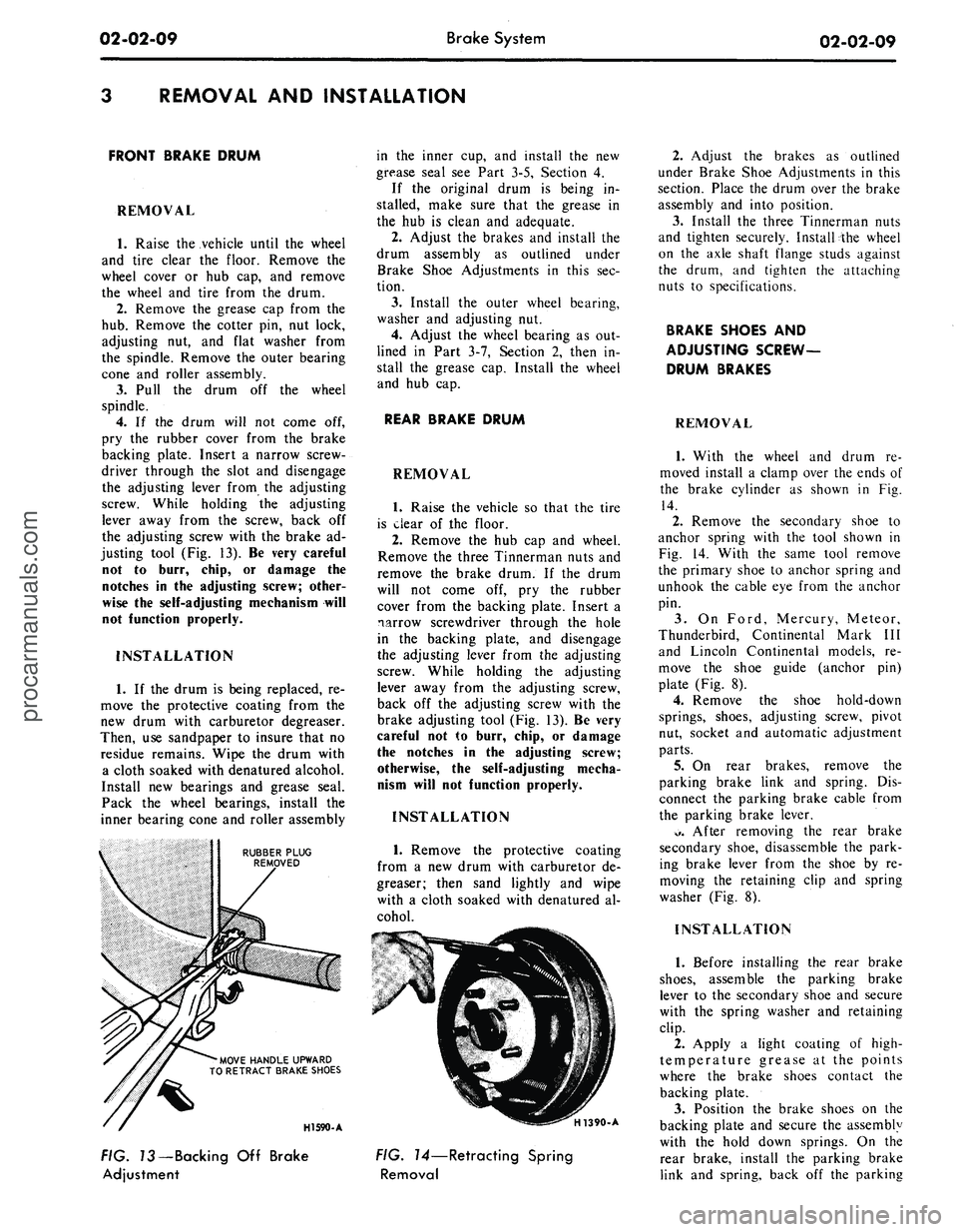
justing tool (Fig. 13). Be very careful
not to burr, chip, or damage the
notches in the adjusting screw; other-
wise the self-adjusting mechanism will
not function properly.
INSTALLATION
1.
If the drum is being replaced, re-
move the protective coating from the
new drum with carburetor degreaser.
Then, use sandpaper to insure that no
residue remains. Wipe the drum with
a cloth soaked with denatured alcohol.
Install new bearings and grease seal.
Pack the wheel bearings, install the
inner bearing cone and roller assembly
RUBBER PLUG
REMOVED
'MOVE HANDLE UPWARD
TO RETRACT BRAKE SHOES
in the inner cup, and install the new
grease seal see Part 3-5, Section 4.
If the original drum is being in-
stalled, make sure that the grease in
the hub is clean and adequate.
2.
Adjust the brakes and install the
drum assembly as outlined under
Brake Shoe Adjustments in this sec-
tion.
3.
Install the outer wheel bearing,
washer and adjusting nut.
4.
Adjust the wheel bearing as out-
lined in Part 3-7, Section 2, then in-
stall the grease cap. Install the wheel
and hub cap.
REAR BRAKE DRUM
REMOVAL
1.
Raise the vehicle so that the tire
is clear of the floor.
2.
Remove the hub cap and wheel.
Remove the three Tinnerman nuts and
remove the brake drum. If the drum
will not come off, pry the rubber
cover from the backing plate. Insert a
narrow screwdriver through the hole
in the backing plate, and disengage
the adjusting lever from the adjusting
screw. While holding the adjusting
lever away from the adjusting screw,
back off the adjusting screw with the
brake adjusting tool (Fig. 13). Be very
careful not to burr, chip, or damage
the notches in the adjusting screw;
otherwise, the self-adjusting mecha-
nism will not function properly.
INSTALLATION
1.
Remove the protective coating
from a new drum with carburetor de-
greaser; then sand lightly and wipe
with a cloth soaked with denatured al-
cohol.
HI 590-A
H1390-A
FIG. 73—Backing Off Brake
Adjustment
FIG. 14—Retracting Spring
Removal
2.
Adjust the brakes as outlined
under Brake Shoe Adjustments in this
section. Place the drum over the brake
assembly and into position.
3.
Install the three Tinnerman nuts
and tighten securely. Install the wheel
on the axle shaft flange studs against
the drum, and tighten the attaching
nuts to specifications.
BRAKE SHOES AND
ADJUSTING SCREW-
DRUM BRAKES
REMOVAL
1.
With the wheel and drum re-
moved install a clamp over the ends of
the brake cylinder as shown in Fig.
14.
2.
Remove the secondary shoe to
anchor spring with the tool shown in
Fig. 14. With the same tool remove
the primary shoe to anchor spring and
unhook the cable eye from the anchor
pin.
3.
On Ford, Mercury, Meteor,
Thunderbird, Continental Mark III
and Lincoln Continental models, re-
move the shoe guide (anchor pin)
plate (Fig. 8).
4.
Remove the shoe hold-down
springs, shoes, adjusting screw, pivot
nut, socket and automatic adjustment
parts.
5.
On rear brakes, remove the
parking brake link and spring. Dis-
connect the parking brake cable from
the parking brake lever.
*>.
After removing the rear brake
secondary shoe, disassemble the park-
ing brake lever from the shoe by re-
moving the retaining clip and spring
washer (Fig. 8).
INSTALLATION
1.
Before installing the rear brake
shoes,
assemble the parking brake
lever to the secondary shoe and secure
with the spring washer and retaining
clip.
2.
Apply a light coating of high-
temperature grease at the points
where the brake shoes contact the
backing plate.
3.
Position the brake shoes on the
backing plate and secure the assembly
with the hold down springs. On the
rear brake, install the parking brake
link and spring, back off the parkingprocarmanuals.com
Page 29 of 413

02-02-10
Brake System
02-02-10
brake adjustment then connect the
parking brake cable to the parking
brake lever (Fig. 8).
4.
Install the shoe guide (anchor
pin) plate on the anchor pin when so
equipped.
5.
Place the cable eye over the an-
chor pin with the crimped side toward
the backing plate.
6. Install the primary shoe to an-
chor spring (Fig. 15).
H1391-A
FIG. 75—Retracting Spring
Installation
7.
Install the cable guide on the
secondary shoe web with the flanged
hole fitted into the hole in the second-
ary shoe web. Thread the cable
around the cable guide groove (Fig.
8).
It
is
imperative that
the
cable
be
positioned
in
this groove
and not be-
tween
the
guide
and the
shoe
web.
8.
Install the secondary shoe to an-
chor spring with the tool shown in
Fig. 15.
Be certain that
the
cable
eye is not
cocked
or
binding
on the
anchor
pin
when installed.
All
parts should
be
flat
on
the
anchor
pin.
Remove
the
brake
cylinder clamp.
9. Apply high-temperature grease
(MIC-100-A) to the threads and the
socket end of the adjusting screw.
Turn the adjusting screw into the ad-
justing pivot nut to the limit of the
threads and then back off 1/2 turn.
Interchanging
the
brake shoe
ad-
justing screw assemblies from
one
side
of
the
vehicle
to the
other would cause
the brake shoes
to
retract rather than
expand each time
the
automatic
ad-
justing mechanism operated.
To pre-
vent installation on the wrong side of
the vehicle, the socket end of the ad-
justing screw is stamped with an R or
L (Fig. 16). The adjusting pivot nuts
can be distinguished by the number of
grooves machined around the body of
the nut. Two grooves on the nut indi-
cate a right thread; one groove indi-
cates a left thread.
10.
Place the adjusting socket on
the screw and install this assembly be-
tween the shoe ends with the adjusting
screw toothed wheel nearest the sec-
ondary shoe.
11.
Hook the cable hook into the
hole in the adjusting lever. The adjust-
ing levers are stamped with an R or L
to indicate their installation on right
or left brake assembly (Fig. 16).
12.
Position the hooked end of the
ADJUSTING LEVER
IDENTIFICATION LINES
H1143-C
FIG. 16—Adjusting Screw
and
Lever Identification
adjuster spring completely into the
large hole in the primary shoe web.
The last coil of the spring should be at
the edge of the hole. Connect the loop
end of the spring to the adjuster lever
hole.
13.
Pull the adjuster lever, cable
and automatic adjuster spring down
and toward the rear to engage the
pivot hook in the large hole in the sec-
ondary shoe web (Fig. 8).
14.
After installation, check the ac-
tion of the adjuster by pulling the sec-
tion of the cable between the cable
guide and the anchor pin toward the
secondary shoe web far enough to lift
the lever past a tooth on the adjusting
screw wheel. The lever should snap
into position behind the next tooth,
and release of the cable should cause
the adjuster spring to return the lever
to its original position. This return ac-
tion of the lever will turn the adjusting
screw.one tooth.
If pulling the cable does not pro-
duce the action described, or if the
lever action is sluggish instead of posi-
tive and sharp, check the position of
the lever on the adjusting screw
toothed wheel. With the brake in a
vertical position (anchor at the top),
the lever should contact the adjusting
wheel 3/16 inch (plus or minus 1/32
inch) above the centerline of the
screw. If the contact point is below
this centerline, the lever will not lock
on the teeth in the adjusting screw
wheel, and the screw will not be turned
as the lever is actuated by the cable.
To determine the cause of this con-
dition:
a. Check the cable end fittings. The
cable should completely fill or extend
slightly beyond the crimped section of
the fittings. If it does not meet this
specification, possible damage is indi-
cated and the cable assembly should
be replaced.
b.
Check the cable length. On
Ford, Mercury, Meteor, Thunderbird,
Continental Mark III, and Lincoln
Continental models, the cable should
measure 11 1/8 inches (plus or minus
1/64 inch) from the end of the cable
anchor to the end of the cable hook.
On Fairlane, Montego, Falcon,
Mustang, and Cougar models the
cable should measure 8 13/32 inches
on 9 inch brakes or 9 3/4 inches on
10 inch brakes from the end of the
cable anchor to the end of the cable
hook.
c. Check the cable guide for dam-
age.
The cable groove should be paral-
lel to the shoe web, and the body of
the guide should lie flat against the
web.
Replace the guide if it shows
damage.
d. Check the pivot hook on the
lever. The hook surfaces should be
square with the body of the lever for
proper pivoting. Replace the lever if
the hook shows damage.
e. See that the adjusting; screw
socket is properly seated in the notch
in the shoe web.
WHEEL CYLINDER
DRUM BRAKE
REMOVAL '
1.
Remove the wheel and the drum.
2.
Remove the brake shoe assem-
blies,
following procedures outlined in
this section.
3.
Disconnect the brake line from
the brake cylinder Figs. 17 thru 21.
On
a
vehicle with
a
vacuum brake
booster,
be
sure
the
engine
is
stopped
and there
is no
vacuum
in the
booster
system before disconnecting
the hy-
draulic lines.
To disconnect the hose at a front
cylinder, loosen the tube fitting that
connects the opposite end of the hose
to the brake tube at a bracket on the
frame. Remove the horseshoe-type re-
taining clip from the hose and brack-
et, disengage the hose from the brack-
et, then unscrew the entire hose as-
sembly from the front wheel cylinder.
At a rear cylinder, unscrew the tubeprocarmanuals.com
Page 30 of 413
TUBE 2B253 TUBE 2263
SWITCH 2B264
TUBE 2265
VIEWZ
DRUM BRAKE
VIEWY
DISC BRAKE
VIEW IN CIRCLE M
VIEW Y
TYPICAL 2 PLACES
DRUM BRAKE
VIEW IN CIRCLE K
H 1639-A
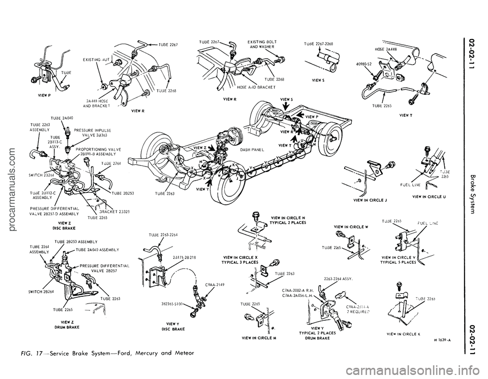
FIG. 17—Service Brake System—Ford, Mercury and Meteorprocarmanuals.com
Page 31 of 413

02-02-12
Brake System
02-02-12
TUBE ASSY. REF.
2 A 040
TUBE ASSY. REF.
2B113-B
PRESSURE
IMPULSE VALVE
PROPORTIONING
TUBE
>Y.
2B253 ASSY REF TUBE
/W W '
Kth#
2263 ASSY. R.H. REF.
TUBE
2B112-E
2264 ASSY. L.H. REF.
2B329
ASSY. REF.
HOSE
C8OA-2B218-C ASSY.L.H.
C80A-26171-D ASSY.R.H.
2B269 ASSY. REF.
VIEWZ
INSTALLATION-DISC BRAKE ONLY
BEND CLIP TO RETAIN
TUBE AS SHOWN
-TUBE
VIEW IN CIRCLE T
382365-S36
WASHER
8M-2149
TUBE-2A040
INSTALLATION-DISC BRAKES SAME AS
DRUM BRAKES AND MAIN VIEW
EXCEPT AS SHOWN
TUBE-2267 R.H.
TUBE-2B253
TUBE 2B329
PRESSURE DIFFERENTIAL
VALVE
TUBE 2B329
VIEW IN
CIRCLE U
TYPICAL ^,
CES^^
CLI
BOLT-
VIEW IN CIRCLE N
WASHER
34808-S8
PART OF AXLE
VENT ON STATION
WAGON ONLY
VENT ASSEMBLY
TUBE ASSEMBLY-2265
STANDARD AND POWER DRUM
3RAKES TUBE ASSEMBLY-2B1T2
POWER DISC BRAKES
MANUAL DISC
TUBE-2263 R.H.
3 REQUIRED
BOLT- 3 REQUIRED
CHECK BRAKE HOSE CLEARANCE „
TO ALL COMPONENTS IN
2A448"
METAL/METAL JOUNCE AND
METAL/METAL REBOUND-
TUBE-2267
ARMOR-390, 428 ENGINES ONLY
8 CYLINDER ENGINE REAR AXLE ONLY
TUBE ASSEMBLY-2268 L.H.
PRESSURE DIFFERENTIAL
VALVE
- GROMMET- 2
jl^REQUIRED
EWYN
TUBE
VIEW P
ROUTING FOR STATION WAGON ONLY
TUBE-22.S5
TUBE-2263 R.H. 2264 L.H.
VIEW IN CIRCLE Y
TYPICAL 2 PLACES
CHECK BRAKE HOSE CLEARANCE TO ALL
COMPONENTS IN METAL/METAL JOUNCE,
METAL/METAL REBOUND AND FULL
INSIDE AND OUTSIDE TURNS
VIEWX
TYPICAL 2 PLACES
DRUM BRAKES
TUBE-2263 R.H
2264 L.H.
VIEW IN CIRCLE U
TYPICAL 4 PLACES
HOSE-2A448
BRAKE HOSE-2078
GASKET-2149 2 REQUIRED
VIEW IN CIRCLE W
TYPICAL 2 PLACES
DRUM BRAKES
LIP
REINFORCEMENT ASSEMBLY-2B222
APPLY ESB-M4632-A SEALER AROUND
STUDS AND SCREW HOLE ON
FLOOR PAN SIDE
TUBE
TUBE ASSEMBLY-226J)
VIEW R
TUBE
VIEW IN CIRCLE M
POWER DISC BRAKES
BRAKE HOSE MUST BE ASSEMBLED
WITH WHEELS STRAIGHT AHEAD.
STRIPE ON HOLE HOSE ASSEMBLY
MUST SHOW NO EVIDENCE OF TWIST.
H 1559-C
—Service Brake
System—Fairlane,
Montego
and
Falconprocarmanuals.com
Page 32 of 413
PRESSURE IMPULSE
VALVE
TUBE-2A040
TUBE-2B253
TUBE-2263 ASSY R.H.
2264 ASSY L.H.
TUBE-2267
PRESSURE
DIFFERENTIAL
VALVE
TUBE-2265
PROPORTIONING
VALVE
TUBE-2B112 \ TUBE-2263
L.H. FENDER APRON REF.
VIEWP
FOR POWER DISC BRAKES
TUBE-2B253
TUBE-
TUBE-22 64
TUBE-2B269
VIEWX
427 & 428 ENGINES 382410-S2
ALL EXCEPT
200 ENGINE
TUBE-2267
HOSE-2A448
TUBE-2265
TUBJ,-2268
VIEWY
ALL EXCEPT 200 ENGINE
PRESSURE DIFFERENTIAL
VALVE -2B257
VIEWS L&M //
BODY CROSSMEMBER
TUBE-2265
L.H. FENDER APRON REF.
VIEWR
FOR DRUM BRAKES
VIEW IN CIRCLE V
TYPICAL 4 PLACES
HOSE-2A448
VIEW IN CIRCLE U
VIEWW
VIEW IN CIRCLE T
VIEW IN CIRCLE S
TYPICAL 4 PLACES
VIEWN
H1640-A
FIG. 19—Service Brake System—Mustang and Cougarprocarmanuals.com