Page 321 of 413

07-02-13
C4 Automatic Transmission
07-02-13
4.
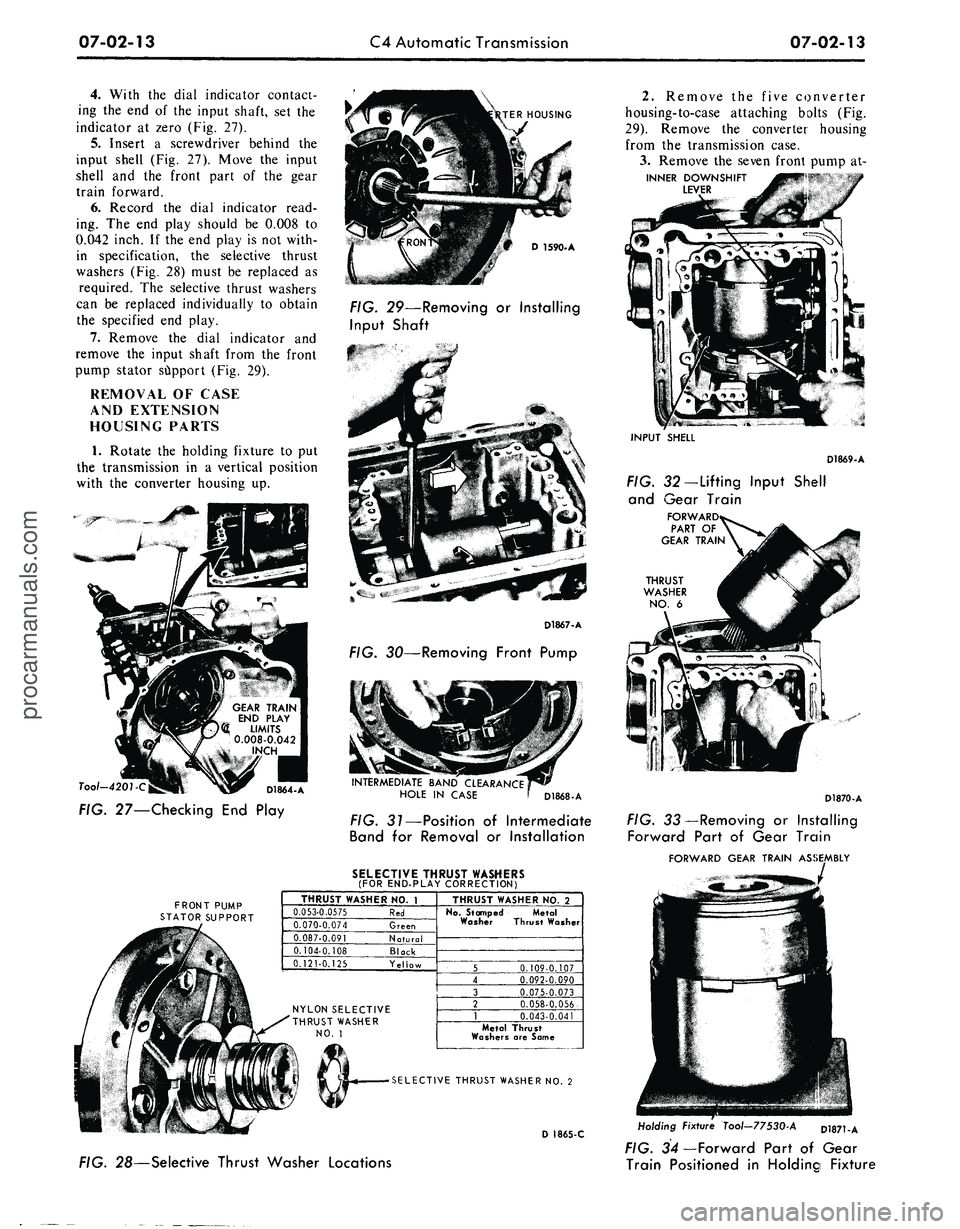
With the dial indicator contact-
ing the end of the input shaft, set the
indicator at zero (Fig. 27).
5.
Insert a screwdriver behind the
input shell (Fig. 27). Move the input
shell and the front part of the gear
train forward.
6. Record the dial indicator read-
ing. The end play should be 0.008 to
0.042 inch. If the end play is not with-
in specification, the selective thrust
washers (Fig. 28) must be replaced as
required. The selective thrust washers
can be replaced individually to obtain
the specified end play.
7.
Remove the dial indicator and
remove the input shaft from the front
pump stator support (Fig. 29).
REMOVAL OF CASE
AND EXTENSION
HOUSING PARTS
1.
Rotate the holding fixture to put
the transmission in a vertical position
with the converter housing up.
•?*
GEAR TRAIN
END PLAY
LIMITS
0.008-0.042
Tool-4201-C
D1864-A
FIG. 27—Checking End Play
TER HOUSING
D 1590-A
FIG. 29—Removing or Installing
Input Shaft
D1867-A
FIG. 30—Removing Front Pump
INTERMEDIATE BAND CLEARANCE
HOLE IN CASE
D1868-A
FIG. 31—Position of Intermediate
Band for Removal or Installation
SELECTIVE THRUST WASHERS
(FOR END-PLAY CORRECTION)
FRONT PUMP
STATOR SUPPORT
THRUST WASHER NO. 1
0.053-0.0575 Red
0.070-0.074 Green
0.087-0.091 Natural
0.104-0.108 Block
0.121-0.125 Yellow
NYLON SELECTIVE
"'THRUST WASHER
NO.
1
EI\
Jtth.
THRUST WASHER NO. 2
No.
Stamped Metal
Washer Thrust Washer
5 0.109-0.107
4 0.092-0.090
3 0.075-0.073
2 0.058-0.056
1 0.043-0.041
Metal Thrust
Washers are Same
SELECTIVE THRUST WASHER NO. 2
D 1865-C
2.
Remove the five converter
housing-to-case attaching bolts (Fig.
29).
Remove the converter housing
from the transmission case.
3.
Remove the seven front pump at-
INNER DOWNSHIFT
LEVER
INPUT SHELL
D1869-A
FIG. 32—
Lifting
Input Shell
and Gear Train
FORWARD
PART
OF
GEAR TRAIN
THRUST
WASHER
NO. 6
D1870-A
FIG. 33—Removing or Installing
Forward Part of Gear Train
FORWARD GEAR TRAIN ASSEMBLY
FIG. 28—Selective Thrust Washer Locations
Holding Fixture Tool—77530-A D1871-A
FIG. 34— Forward Part of Gear
Train Positioned in Holding Fixtureprocarmanuals.com
Page 322 of 413

07-02-14
C4 Automatic Transmission
07-02-14
FORWARD CLUTCH
FORWARD CLUTCH FRONT PLANET CARRIER INPU^ SHELL
HUB AND
RING GEAR
SUN GEAR
REVERSE-HIGH CLUTCH
THRUST WASHER
NO.
5
FIG. 35—Forward Part of Gear Train Disassembled
D1872-A
taching bolts. Remove the front pump
by inserting a screwdriver behind the
input shell (Fig. 30). Move the input
shell forward until the front pump seal
is above the edge of the case.
Remove the front pump and gasket
from the case. If the selective thrust
washer No. 1 did not come out with
the front pump, remove it from the
top of the reverse-high clutch.
4.
Remove the intermediate and
low-reverse band adjusting screws
from the case. Rotate the intermediate
band to align the band ends with the
clearance hole in the case (Fig. 31).
Remove the intermediate band from
the case.
5.
Using a screwdriver between the
input shell and rear planet carrier
(Fig. 32), lift the input shell upward
and remove the forward part of the
gear train as an assembly (Fig. 33).
6. Place the forward part of the
gear train in the holding fixture shown
in Fig. 34.
7.
From the gear train in the hold-
ing fixture, remove the reverse-high
clutch and drum from the forward
clutch (Fig. 35).
8. If thrust washer No. 2 (Fig. 28)
did not come out with the front pump,
remove the thrust washer from the
forward clutch cylinder. Remove the
forward clutch from the forward
clutch hub and ring gear (Fig. 35).
9. If thrust washer No. 3 (Fig. 35)
did not come out with the forward
clutch, remove the thrust washer from
the forward clutch hub.
10.
Remove the forward clutch hub
and ring gear from the front planet
carrier (Fig. 35).
11.
Remove thrust washer No. 4
and the front planet carrier from the
input shell.
12.
Remove the input shell, sun
gear and thrust washer No. 5 from the
holding fixture.
13.
From inside the transmission
case (Fig. 33) remove thrust washer
No.
6 from the top of the reverse
planet carrier.
14.
Remove the reverse planet car-
rier and thrust washer No. 7 from the
reverse ring gear and hub (Fig. 36).
15.
Move the output shaft forward
and with the tool shown in Fig. 37 re-
move the reverse ring gear hub-
to-output shaft retaining ring.
16.
Remove the reverse ring gear
and hub from the output shaft. Re-
move thrust washer No. 8 from the
low and reverse drum.
17.
Remove the low-reverse band
from the case (Fig. 38).
18.
Remove the low-reverse drum
from the one-way clutch inner race
(Fig. 36).
19.
Remove the one-way clutch
inner race by rotating the race clock-
wise as it is removed.
20.
Remove the 12 one-way clutch
rollers, springs and the spring retainer
from the outer race (Fig. 36). Do not
lose or damage any of the 12 springs
REVERSE PLANET CARRIER
THRUST WASHER NO. 8
THRUST WASHER NO. 9
SPRING RETAINER
INNER RACE
THRUST WASHER NO. 6
LOW AND REVERSE DRUM
ONE-WAY
CLUTCH
SPRINGS (12)
AND ROLLERS (12)
OUTER RACE
D1394-A
FIG. 36—Lower Part of Gear Train Disassembledprocarmanuals.com
Page 323 of 413

07-02-15
C4 Automatic Transmission
07-02-15
GOVERNOR DISTRIBUTOR
REVERSE RING GEAR
HUB RETAINING RING
D 2044-A
FIG.
37—Removing
or
Installing
Reverse
Ring Gear
Hub
Retaining
Ring
I®
LOW-RE'VERSE BAND
D1873-A
FIG.
38—Removing
or
Installing
Low-Reverse
Band
OUTPUT SHAFT
GOVERNOR
DISTRIBUTOR
SLEEVE
D1875-A
FIG.
39—Removing
or
Installing
Output
Shaft
and
Governor
Distributor
LOCK RING
D1876-A
FIG.
40—Removing
or
Installing
Governor
Distributor Snap Ring
or rollers.
The
outer race
of the one-
way clutch cannot
be
removed worn
the case until
the
extension housing,
output shaft
and
governor distributor
sleeve
are
removed.
21.
Remove
the
transmission from
the holding fixture. Position
the
trans-
mission
on the
bench
in a
vertical
po-
sition with
the
extension housing
up.
Remove
the
four extension housing-
to-case attaching bolts. Remove
the
extension housing
and
gasket from
the
case.
22.
Pull outward
on the
output
shaft
and
remove
the
output shaft
and
governor distributor assembly from
the governor distributor sleeve
(Fig.
39).
23.
Remove
the
governor distribu-
tor lock ring from
the
output shaft
(Fig.
40).
Remove
the
governor
dis-
tributor from
the
output shaft.
24.
Remove
the
four distributor
sleeve-to-case attaching bolts. Remove
the distributor sleeve from
the
case.
Do
not
bend
or
distort
the
fluid tubes
as
the
tubes
are
removed from
the
case with
the
distributor sleeve.
25.
Remove
the
parking pawl
re-
turn spring, pawl,
and
pawl retaining
pin from
the
case (Fig.
41).
26.
Remove
the
parking gear
and
thrust washer
No. 10
from
the
case.
27.
Remove
the six
one-way clutch
outer race-to-case attaching bolts with
the tool sh^'vn
in
Fig. 42.
As the
bolts
are removed, hold
the
outer race
lo-
cated inside
the
case
in
position.
Re-
move
the
outer race
and
thrust washer
No.
9
from
the
case (Fig.
36).
Too/-
T65P.7B456-8
D1879-A
FIG.
42—Removing One-Way
Clutch
Outer Race
Attaching
Bolts
PARKING GEAR
i^ffif
THRUST WASHER NO. 10 ^*t^
$
D1399-A
FIG.
41—Parking
Pawl,
Return Spring Retaining
Pin and
Gearprocarmanuals.com
Page 324 of 413

07-02-16
C4 Automatic Transmission
07-02-16
COVER SEAL
STEM NUT
SERVO PISTON STEM
PISTON RETURN SPRING PISTON AND SEAL
(SEAL BONDED TO PISTON)
FIG. 43—Low-Reverse Servo Disassembled
PARTS REPAIR OR
REPLACEMENT
During the repair of the sub-
assemblies, certain general instructions
which apply to all units of the trans-
missions must be followed. These in-
structions are given here to avoid un-
necessary repetition.
Handle all transmission parts care-
fully to avoid nicking or burring the
bearing or mating surfaces.
Lubricate all internal parts of the
transmission before assembly with
clean automatic transmission fluid. Do
not use any other lubricants except on
gaskets and thrust washers which may
be coated with vaseline to facilitate
assembly. Always install new gaskets
when assembling the transmission.
Tighten all bolts and screws to the
recommended torque as outlined in
the Specification Section.
TRANSMISSION CASE AND
LINKAGE REPAIR
Low-Reverse Servo
1.
Remove the four servo cover-
to-case attaching bolts. Remove the
vent tube and retaining clip from the
case.
2.
Remove the servo cover, cover
seal, servo piston and piston return
spring from the case (Fig. 43).
3.
The servo piston seal is bonded
to the piston. If the seal has to be re-
placed, replace the piston assembly
which includes the seal. Disassemble
the servo piston from the piston stem
by inserting a small screwdriver in the
hole of the piston stem and removing
the piston attaching nut (Fig. 44).
Position the accumulator spring and
spacer (Fig. 43) on the piston stems.
Make sure the crowned side of the
spring is facing toward the rod. Install
the new servo piston and attaching nut
COVER
D1880-A
LOW-REVERSE
PISTON
D1881-A
FIG. 44—Removing or Installing
Low-Reverse Servo Piston
on the stem, torque the nut to specifi-
cation.
4.
Place the piston return spring in
the servo bore of the case. Lubricate
the piston seal with clean transmission
fluid and install the servo pistion into
the bore of the case.
5.
Place a new cover seal on the
cover and install the servo cover. In-
stall the vent tube and retaining clip.
Install the four cover attaching bolts.
Torque the cover-to-case retaining
bolts to specifications.
Intermediate Servo
1.
Remove the transmission
identif-
ication tag and the four servo cover to
case attaching bolts.
2.
Remove the servo cover, gasket,
servo piston, and piston return spring
from the case (Fig. 45).
3.
Remove the intermediate servo
piston from the cover.
4.
Remove the seal rings from the
servo piston and cover.
5.
Install a new seal on the cover
and servo piston. Figure 46 shows the
correct servo piston and cover for
each transmission model. Lubricate
the seals with clean transmission fluid.
Install the piston into the cover. Be
careful not to damage the piston seal.
6. Install the piston return spring in
the servo bore of the case.
7.
Place a new gasket on the servo
cover. Position the servo piston and
cover assembly into the case with the
piston stem slot in a horizontal posi-
tion to engage the strut. Use two
5/16-18 bolts, 1 1/4 inch long, 180
degrees apart, to position the cover
against the case. Install two cover at-
taching bolts. Remove the two 1 1/4
V-8 ENGINE
COVER
RETURN SPRING
PISTON
COVER SEAL COVER^ GASKET
PISTON SEALS
6 CYLINDER ENGINE
COVER
D1882-A
FIG. 45—Intermediate Servo Disassembledprocarmanuals.com
Page 325 of 413

07-02-17
C4 Automatic Transmission
07-02-17
Vehicle
Ford,
Meteor
Fairlane,
Montegc,
Falcon,
Mustang
Ford,
Meteor
Fairlane,
Montego,
Mustang
Mustang
Falcon
Engine
302-2V
302-2V
240-IV
250-1V
200-1V
170-1V
200-1V
Transmi ssion
PEA-MI,
Nl
PEE-M,
V, AC
PEA-A2
PEE-AD,
AE,
AF
PEB-B2
PEB-C2
Servo Piston
Dia.
A
3.7875
3.7875
3.3265
Dia.
B
2.8265
2.7065
2.4865
Servo Cover
Dia.
C
None
None
3.340
Dia.
D
2.840
2.975
2.500
Spring
Free Length
(Inches)
2.480
2.480
2.480
Color
Cniif
White
White
White
D 1800-D
FIG. 46—Intermediate Servo Piston, Cover and Spring Identification
inch bolts and install the transmission
identification tag and the other two
cover attaching bolts. Torque the bolts
to specifications.
Downshift and Manual
Linkage
1.
Apply penetrating oil to the
outer lever attaching nut to prevent
UPPER RETAINING RING
breaking the inner lever shaft. Remove
the downshift outer lever nut. Remove
the downshift outer and inner lever.
From inside the transmission case, re-
move the upper retaining ring from
the manual lever link (Fig. 47). Re-
move the upper end of the lever link
from the case retaining pin.
2.
From the back of the transmis-
sion case, remove the upper retaining
INNER MANUAL
'ER ATTACHING NUT
mmMm
INNER MANUAL LEVER MANUAL LEVER LINK
FIG. 47—Case Internal Linkage
ring and flat washer from the parking
pawl link (Fig. 48). Remove the pawl
link from the case retaining pin.
3.
From the back of the transmis-
sion case, remove the parking pawl
link, toggle rod, and manual lever link
as an assembly (Fig. 49).
UPPER
r RETAINING
RING
D1885-A
FIG. 48—Parking Pawl Link
/7^-MANUAL LEVER LINK
D1405-B
FIG. 49—Removing or Installing
Parking Pawl Link
4.
Remove the rear parking pawl
link lower retaining ring, flat washer
and link from the toggle rod (Fig. 50).
5.
Remove the manual lever link,
lower retaining ring, flat washer, and
link from the toggle rod.
6. Install the manual and marking
pawl links, flat washers and retaining
rings to the toggle rods.
7.
Remove the inner manual lever
attaching nut and lever. Remove the
outer manual lever from the case.
8. To remove the manual lever seal,
use the tools shown in Fig. 51. To in-
stall the new seal, use a driver that fits
the ID of the seal.
9. Install the outer manual lever in
the case. Install the inner manual
lever and attaching nut with the cham-
fer facing toward the lever (Fig. 47).
Torque the nut to specification.
10.
From the back of the transmis-
sion case, install the parking toggle
rod and link assembly into the case
(Fig. 49).
11.
Install the parking pawl link on
the case retaining pin. Install the flat
washer and link retaining ring (Fig.
48).procarmanuals.com
Page 326 of 413

07-02-18
C4 Automatic Transmission
07-02-18
OUTER MANUAL LEVER
MANUAL LEVER LINK
INNER MANUAL LEVER
PARKING PAWL LINK
TOGGLE ROD
PARKING PAWL LINK
FIG. 50—Case Linkage
D1888-A
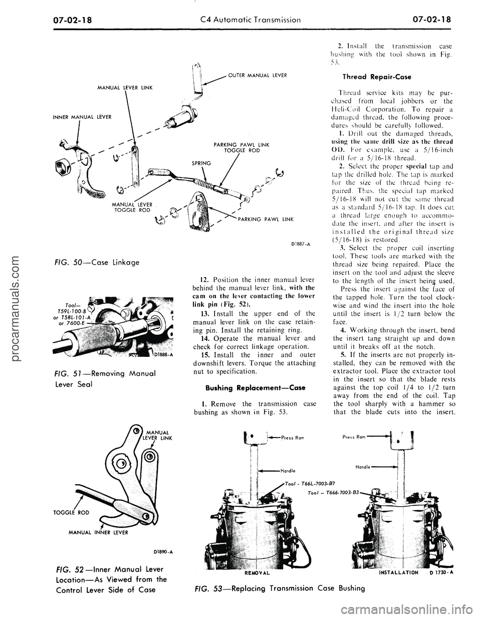
FIG. 51—Removing Manual
Lever Seal
TOGGLE ROD
D1887-A
12.
Position the inner manual lever
behind the manual lever link, with the
cam on the lever contacting the lower
link pin (Fig. 52).
13.
Install the upper end of the
manual lever link on the case retain-
ing pin. Install the retaining ring.
14.
Operate the manual lever and
check for correct linkage operation.
15.
Install the inner and outer
downshift levers. Torque the attaching
nut to specification.
Bushing Replacement—Case
1.
Remove the transmission case
bushing as shown in Fig. 53.
Press Ram
Handle
MANUAL INNER LEVER
D1890-A
FIG. 52— Inner Manual Lever
Location—As Viewed from the
Control Lever Side of Case
2.
Install the transmission case
bushing with the tool shown in Fig.
53.
Thread Repair-Case
Thread service kits may be pur-
chased from local jobbers or the
Heli-Coil Corporation. To repair a
damaged thread, the following proce-
dures should be carefully followed.
1.
Drill out the damaged threads,
using the same drill size as the thread
01).
For example, use a 5/16-inch
drill for a 5/16-18 thread.
2.
Select the proper special tap and
tap the drilled hole. The tap is marked
for the size of the thread being re-
paired. Thus, the special tap marked
5/16-18 will not cut the same thread
as a standard 5/16-18 tap. It does cut
a thread large enough to accommo-
date the insert, and after the insert is
installed the original thread size
(5/16-18) is restored.
3.
Select the proper coil inserting
tool. These tools are marked with the
thread size being repaired. Place the
insert on the tool and adjust the sleeve
to the length of the insert being used.
Press the insert against the face of
the tapped hole. Turn the tool clock-
wise and wind the insert into the hole
until the insert is 1/2 turn below the
face.
4.
Working through the insert, bend
the insert tang straight up and down
until it breaks off at the notch.
5.
If the inserts are not properly in-
stalled, they can be removed with the
extractor tool. Place the extractor tool
in the insert so that the blade rests
against the top coil 1/4 to 1/2 turn
away from the end of the coil. Tap
the tool sharply with a hammer so
that the blade cuts into the insert.
Press Rom
Handle
Too/
- T66L-7003-B7
Tool - T666-7003-B3
REMOVAL INSTALLATION D 1730-A
FIG. 53—Replacing Transmission Case Bushingprocarmanuals.com
Page 327 of 413

07-02-19
C4 Automatic Transmission
07-02-19
Tool-T64P-7A128-A
OIL
SCREEN
LOWER
VALVE BODY
-,
-^L*«^M*if
GASKET
UPPER
VALVE BODY
D1891-A
FIG. 54—Upper and Lower Valve Bodies Disassembled
MANUAL VALVE
D1892-A
FIG. 56—Removing Manual Valve
Exert downward pressure on the tool
and turn it counterclockwise until the
insert is removed.
CONTROL VALVE BODY
Disassembly
1.
Remove the eight screws that at-
tach the oil screen to the body and re-
move the screen (Fig. 54).
2.
Remove the seven attaching
screws from the underside of the lower
valve body. Separate the lower valve
body, gasket, separator plate and
hold-down plates (Fig. 55) from the
upper valve body. Be careful not to
lose the upper valve body steel ball
shuttle valve and spring when separat-
ing the upper and lower valve bodies.
3.
Depress the manual valve detent
spring with the tool shown in Fig. 56.
Remove the spring retaining pin (roll
SEPARATOR
PLATE
pin) from the upper valve body. Re-
move the spring and detent plunger.
4.
Slide the manual valve out of the
body.
5.
Remove the cut-back and the
back-out valve cover plate from the
valve body (Fig. 57).
6. Remove the cut-back valve from
the body.
7.
Remove the 2-3 back-out valve,
spring and the manual low valve from
the body.
8. Remove the 1-2 shift valve and
2-3 shift valve cover plate from the
valve body.
9. Remove the 2-3 shift valve and
the throttle modulator valve from the
body.
10.
Remove the 1-2 shift valve, D2
valve and the spring from the body.
11.
Remove the intermediate band
accumulator valve cover plate from
the valve body.
RUBBER BALL
SHUTTLE VALVE
SERVO
CHECK VALVE
RUBBER BALL
SHUTTLE VALVE
UPPER VALVE
BODY
D 1726-A
FIG. 55—Separating Upper and Lower Valve Bodies
12.
Remove the intermediate accu-
mulator sleeve, 3-2 control valve,
spring and the intermediate servo ac-
cumulator valve.
13.
Remove the pressure booster
valve, cover plate (Fig. 57).
14.
Remove the pressure booster
valve, sleeve, springs and the main re-
gulator valve.
15.
Remove the spring and the line
pressure coasting boost valve (Fig.
57).
16.
Carefully pry the downshift
valve retainer from the body, then re-
move the spring and valve.
17.
Hold the upper valve body as
shown in Fig. 58 and depress the
throttle booster valve plug to release
the retaining pin. Remove the plug,
valve and the spring.
18.
Remove the two hold-down
plates and the separator plate from
the lower body. Be careful not to lose
the rubber ball shuttle valve when re-
moving the separator plate and gasket
from the lower valve body.
Assembly
1.
Place the rubber ball shuttle
valve in the lower body as shown in
Fig. 55. Position the separator plate
and the two hold-down plates on the
lower valve body and install the four
attaching screws and torque them to
specification.
2.
Place the throttle booster valve
spring, valve (long end into spring)
and the plug (Fig. 57). Depress the
plug and install the retaining pin.
3.
Insert the downshift valve into
the body with the large diameter fac-
ing inward. Install the downshift valve
spring and the retainer (Fig. 57).procarmanuals.com
Page 328 of 413
07-02-20
C4 Automatic Transmission
07-02-20
1-2 SHIFT VALVE
SLEEVE
D2 VALVE
3-2 CONTROL VALVE
ACCUMULATOR
VALVE
UPPER BODY
MAIN REGULATOR
VALVE
2-3 BACK-OUT VALVE
CUT-BACK VALVE
2-3 SHIFT VALVE
MANUAL LOW VALVE
THROTTLE MODULATOR VALVE
THROTTLE BOOSTER VALVE
stmina—E
\
RETAINER
MANUAL VALVE DETENT
PLUG,
SPRING AND
RETAINING PIN
MANUAL VALVE
CONTROL PRESSURE
BOOSTER VALVE
AND SLEEVE
D 1727-A
FIG. 57—Upper Valve Body Disassembledprocarmanuals.com