Page 401 of 413

07-05-01
Specifications
07-05-01
PART
7-5
Specifications
APPROXIMATE
REFILL
CAPACITIES
FMX
Transmission—All
Car
Lines
C4
Transmission—Ford
All
Engines
Falcon
and
Mustang—170
and 200
Engines
All Other
Engines
C6Transmission—Lincoln,
Mark
III
All Other Models
U.S.
Measure
11
qt.
WA
qt.
8
qt.
9
qt.
13
qt.
123/4
qt.
Imperial
Measure
9M
qt.
8Va
qt.
V/i
qt.
7%
qt.
103/4
qt.
10VS
qt.
CONVERTER IDENTIFICATION
AND
STALL SPEEDS
FMX
TRANSMISSION
Converter Part Number
C90P-7902-A
C8AP-7902-D
Nominal
Size
12
12
Stall
Ratio
2.05:1
2.05:1
Identification
No.
0
54
48
Transmission
Model
PHD-A
PHD-B
PHB-C,
D, E,
PHB-F,
G, H,
PHB-A
Engine
CID
240-IV
302-2V
351-2V
351-4V
390-2V
Stall
Speed
1300-1500
1450-1650
1580-1780
1650-1850
1680-1880
®
Converter identification
is
stamped
on the
converter cover adjacent
to the
converter drive
stud.
C4
TRANSMISSION
Converter Part Number
C5DP-7902-D
C8AP-7902-E
C8ZP-7902-A
Nominal
Size
ioy4
12
11V4
Stall
Ratio
2.10:1
2.05:1
2.02:1
Identification
No.®
AL
BB
BC
Transmission
Model
PEB-C2
PEB-B2,
C2
PEA-A2,
PEA-MI,
Nl
PEE-AD,
AE,
AF
PEE-M,
V, AC
Engine
CID
170-1V
200-IV
240-IV
302-2
V
250-IV
302-2V
Stall
Speed
1400-1600
1500-1700
1300-1500
1450-1650
1630-1830
1800-2000
®
Converter identification
is
stamped
on the
converter cover adjacent
to the
converter drive
stud.
C6
TRANSMISSION
Converter Part Number
C8AP-7902-A
C8OP-7902-A®
C8SP-7902-A
C8OP-7902-A®
C8VP-7902-B
C8OP-79O2-A0
C8OP-7902-B
C8OP-7902-A
Nominal
Size
12
12
12
12
12
Stall
Ratio
2.05:1
2.05:1
2.05:1
2.05:1
2.05:1
Identification
No.®
44
46
52
55
53
Transmission
Model
PGA-A3
PGA-J3 PGB-G2
PGB-JI,
AD, AE
PGC-B,
Cl
PGA-A3,
J3, G2
PGB-G2
PGA-AC,AD,AE
PGB-F2,
®
H2
PGA-Z, AA, AB
PGB-AF-1,
AG, AH
Engine
CID
390-2V©®
429-4V
460-4V
390-2V®®
390-4V
390-4V
©
428-4V
429-2V
427-4V
428-4V
CJ
Stall
Speed
1680-:,900
1880-2100
1950-2150
1680-1880
1740-1940
1760-1980
1850-2050
1820-2020
1850-2050
1830-2030
D
Converter identification
is
stamped
on the
converter cover adjacent
to the
converter drive
stud.
v
Regular
©
Premium Fuel
0
Service Replacement
®
Improved Performance
®
Poli
Police Interceptorprocarmanuals.com
Page 402 of 413

07-05-02
Specifications
07-05-02
CONTROL PRESSURE AT ZERO GOVERNOR RPM
-
FMX TRANSMISSION
Engine Speed
Idle
As Required
As Required
D
At
altitudes above
sea
refer
to the
following
Throttle
Closed
As Required
As Required
LJanifnlrl
ManiioiQ
Vac.
Ins.
Hg.
Above 18
®
10
Below
10
Range
P, N, D,
2,1
R
D,2,
1
D, 2,
1
R
Control Line Pressure
(PSI)
PHB-A,
C, D, E,
57-73
66-101
83-110
147-173
191-213
level,
it may not be
possible
to
obtain
18
inches
of
engine vacuum
at
idle.
For
idle vacuum
of
less than
table
to
determine idle speed pressure specification
in D
driving range.
Engine Vacuum
17 inches
16 inches
15 inches
14 inches
13 inches
12 inches
11 inches
Line Pressure
57-67
57-67
57-72
57-79
57-86
57-92
57-99
PHB-F,
G, H-
PHD-A,B
5777
64105
82111
146-175
201-213
18 inches,
C4 TRANSMISSION
Engine
Speed
Idle
As Required
As Required
Throttle
Closed
As Required
As Required
Manifold
Vac.
Ins. Hg
0) Above
18
10
Below
1.0
Range
P,
N, D.
2,
1
R
D,
2, 1
D,
2, 1
R
P.S.I.
55-61
55-102
55-182
93-101
142-150
254-268
0)
At
altitudes above
sea
level,
it
may
not be
possible
to
obtain
18
inches
of
engine vacuum
at
idle.
For
idle vacuums
of
less than
18 inches, refer
to
the
following table
to
determine idle speed pressure specification
in D
driving range.
Engine Vacuum Line Pressure
17 inches 55-66
16 inches
55-71
15 inches 55-76
14 inches
55-81
13 inches 55-86
12 inches
55-91
11 inches 55-96
C6 TRANSMISSION
Engine Speed
Throttle
Manifold Vacuum (Inches
Hg)
Range
psi
@
Barometric
Pressure
®
psi@
Barometric
Pressure
®
Barometric
Pressure
in
Inches
HG
29.5
28.5
27.5
26.5
25.5
24.5
23.5
Nominal
Altitude
(Feet)
Sea Level
1000
2000
3000
4000
5000
6000
Idle
Closed
Above
18 (o
Control
Pressure
(psi)
P,
N, D, 2, 1
56-62
49-59
49-56
49-56
49-56
49-56
49-56
R
71-86
65-30
60-75
56-71
56-65
56-65
56-65
TV
Pressure
(psi)
7-10
4-7
2-5
0-3
0
0
0
As Required
As Required
10
Control
Pressure
(psi)
0,2,1
100-115
99-114
96-111
91-106
88-103
84-98
80-55
TV
Pressure
(psi)
40-44
37-41
35-69
32-36
30-34
27-31
25-29
As Required
As Required
Below
1.0
Control
Pressure (DSI)
D,
2, 1
160-190
158-176
156-174
151-169
146-164
143-161
138-156
R
240-300
233-290
228-284
222-277
215-269
211-264
204-256
TV
Pressure
(psi)
77-84
74-80
72-78
69-75
66-72
64-70
61-67procarmanuals.com
Page 403 of 413

07-05-03
Specifications
07-05-03
C6 TRANSMISSION (Continued)
Manifold Vacuum
17
16
15
14
13
12
11
Barometric Pressure at 29.5 Inches <2)
T.V.
11-14
15-18
20-22
23-26
28-31
32-35
36-40
Cont.
56-69
56-75
56-S4
56-92
56-98
56-105
56-111
Barometric Pressure at 24.5 Inches ®
T.V.
0-1
2-5
7-9
10-13
15-18
19-22
23-27
Cont.
49-56
49-56
49-61
56-67
56-75
56-84
56-92
© It may not be possible to obtain 18 inches of engine vacuum at idle. For idle vacuums of less than 18 inches the following table
provides idle speed pressure specifications in D range:
£> These specifications (with altitude compensating diaphragm) apply at observed barometric pressure of 29.5 inches (nominal sea level)
© Specifications for barometric pressures of less than 29.5 inches.
At barometric pressures between 29.5 inches and 24.5 inches idle, pressures should fall between the values shown.
CHECK
SAND ADJUSTMENTS
FMX TRANSMISSION
Operation
Transmission End Play Check
Turbine and Stator End Play Check
Front Band Adjustment (Use 1/4 inch spacer
between adjustment screw and servo piston
stem)
Rear Band Adjustment, Model PHB-A.PHD
Rear Band Adjustment,
Model PHB-C, D, E, F, G, H
Primary Sun Gear Shaft Ring End Gap Check
Rear Clutch Selective Snap Ring Thicknesses
Specification
0.010-0.029 (Selective Thrust Washers Available)
PHB,
PHD-New or rebuilt 0.023 max., Used 0.030 max.®
Adjust screw to 10 in-lbs torque. Remove spacer, then tighten screw an additional 3/4 turn
and lock.
Adjust screw to 10 in-lbs torque. Remove spacer, then tighten screw an addition 3/4 turn
Adjusting Internally: Loosen internal locknut. Install spacer tool number T69P-7B193-A between
internal adjusting screw and servo piston, tighten internal adjusting screw to 24 in-lbs torque.
Back off 1 1/2 turns. Hold screw and tighten locknut. Remove spacer.
Adjusting Externally: Loosen internal locknut and reset internal adjusting screw to 0.27-0.28
inch.
Tighten internal locknut. Loosen external locknut and adjust external adjusting screw to 10 ft-lbs
torque. Back off 1 1/2 turns. Hold screw and tighten locknut.
0.002-0.009
0.060-0.064, 0.074-0.078, 0.080-0.092, 0.102-0.106
® To check end play, exert force on checking tool to compress turbine to cover thrust washer wear plate. Set indicator at zero.
C4 TRANSMISSION
Operation
Transmission End Play
Turbine and Stator End Play
Intermediate Band Adjustment
Low-Reverse Band Adjustment
Selective Snap Ring Thickness
Specification
0.008-0.042 inch (Selective Thrust Washers Available)
Model PEB -New or rebuilt 0.044 max., Used 0.060 max.
Model PEE, PEA New or rebuilt 0.023 max., Used 0.040 max.
Remove and discard lock nut. Adjust screw to 10 ft-lbs torque, then back off
1-3/4 turns. Install new lock nut and torque to specification.
Remove and discard lock nut. Adjust screw to 10 ft-lbs torque, then back off 3 turns.
Install new locknut and torque to specification.
0.102-0.106, 0.088-0.092, 0.074-0.078, 0.060-O.064procarmanuals.com
Page 404 of 413

07-05-04
Specifications
07-05-04
C6 TRANSMISSIONS
Operation
Transmission End Play
Turbine and Stator End Play
Intermediate Band Adjustment
Forward Clutch Pressure
Plat eto-Snap Ring Clearance
Selective Snap Ring Thicknesses
Reverse-High Clutch Pressure
Plate-to-Snap Ring Clearance
Selective Snap Ring Thicknesses
Specification
0.008-0.044 (Selective Thrust Washers Available)
New or rebuilt 0.021 max., Used
0.030
max. G)
Remove and discard lock nut. Adjust screw to 10 f
t
-
lbs
torque, then back off 1
turn,
install new lock nut and tighten lock nut to specification.
0.031-0.044
0.056-0.060, 0.065-0.069, 0.074-0.078, 0.083-0.087, 0.092-0.096
Transmission Models
PGA
0.022-0.036
PGB,
PGC
0.027-0.043
0.065-0.069, 0.074-0.078, 0.083-0.087
(D To check end play, exert force on checking tool to compress turbine to cover thrust washer wear plate. Set indicator at zero.
SELECTIVE THRUST WASHERS
FMX TRANSMISSION
Identification No.
By Thickness
Thrust Washer Thickness -Inch
0.061-0.063
0.067-0.069
Identification No.
By Thickness.
Thrust Washer Thickness - Inch
0.074-0.076
0.081-0.083
C4 TRANSMISSION
Nylon Thrust Washer
W/Tangs
0.053-4.0575
0.070-0.074
0.087-0.091
0.104-0.108
0.121-0.125
THRUST WASHER NO. 1
Color Of
Washer
Red
Green
Natural (White)
Black
Yellow
No.
Stamped
On Washer
1
2
3
4
5
THRUST WASHER NO. 2
Metal Thrust
Washer
0.041-0.043
0.056-O.058
0.073-0.075
0.090-0.092
0.107-0.109
C6 TRANSMISSION
Identification No.
1
2
3
Thrust Washer Thickness -Inch
0.056-0.058
a.073-0.07F
0.088-0.090
Identification No.
4
5
Thrust Washer Thickness - Inch
0.103-0.105
0.118-0.120
CLUTCH PLATES
FMX TRANSMISSION
Transmission
Model
PHB,
PHD
FORWARD CLUTCH
Steel
Plates
4
Friction
Plates
5©
Selective Plate
Thicknesses
0.0605-0.063
0.0785-0.081
0.0965-0.099
Selective Plate
Identification
No Stripe
One Stripe
Two Stripes
REAR CLUTCH
Steel
Plates
5®
Friction
Plates
4
Free Pack
Clearance
0.030-0.055
© Last plate (Friction) in FMX forward clutch is selective. Install thickest plate in pack that will be a minimum of 0.010 inch below input shaft shoulder
in cylinder. All other friction plates in* pack are thinnest available.
© Plus one waved plate installed between two steel plates at piston end of pack.procarmanuals.com
Page 405 of 413

07-05-05
Specifications
07-05-05
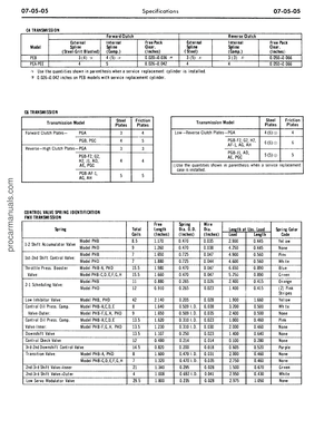
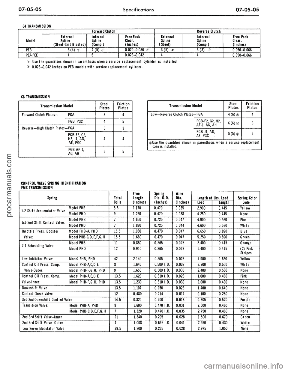
C4 TRANSMISSION
Model
PEB
PEA-PEE
Forward Clutch
External
Spline
(Steel-Grit Blasted)
3(4) '.,
4
Internal
Spline
(Comp.)
4
(5)
>.r<
5
Free Pack
Clear.
(Inches)
0.020-0.036 <*
0.026-0.042
Reverse Clutch
External
Spline
(Steel)
3(5) j)
4
Internal
Spline
(Comp.)
3(3)
J>
4
Free Pack
Clear.
(Inches)
0.050-0.066
0.050-0.066
i Use the quantities shown in parenthesis when a service replacement cylinder is installed.
$•
0.026-0.042 inches on PEB models with service replacement cylinder.
C6 TRANSMISSION
Transmission Model
Forward Clutch Plates- PGA
PGB,
PGC
Reverse-High Clutch Plates-PGA
PGB-F2,
G2,
H2J1,
AD,
AE,
PGC
PGB-AF-1,
AG,
AH
Steel
Plates
3
4
3
4
5
Friction
Plates
4
5
3
4
5
Transmission Model
Low-Reverse Clutch Plates-PGA
PGB-F2,
G2, H2,
AF-1,
AG,
AH
PGB-J1,
AD,
AE,
PGC
Steel
Plates
4(6)®
6(6)©
5(5)®
Friction
Plates
4
6
5
©Use the quantities shown in parenthesis when a service replacement
case is installed.
CONTROL VALVE SPRING IDENTIFICATION
FMX TRANSMISSION
Spring
1 2 Shift Accumulator Valve '° C
Model
PHD
W °nri Shift Pnntrnl Vilur
Model PHD
Throttle Press. Booster Model PHB-A, PHD
Valve:
Model PHB-C,D,E,F,G,H
M Scheduling Valve-
M°delPHB
. 1 Scheduling Valve. Mode, PHD
Low Inhibitor Valve: Model PHB, PHD
Control Oil Press. Comp. Model PHB-A,C,D,E
Valve-Outer: Model PHB-F,G,H, PHD
Control Oil Press. Comp. Model PHB-A,C,D,E
Valve-Inner: Model PHB-F,G,H, PHD
Downshift Valve
Control Check Valve
3rd-2ndDownshift Control Valve
Transition Valve: Model PHB-A, PHD
Model PHB-C,D,E,F,G,H
2nd-3rd Shift Valve-Inner
2nd-3rd Shift Valve-Outer
Low Servo Modulator Valve
Total
Coils
8.5
9
7
7
15.5
15.5
11
12
42
8
9
13.5
13.5
13.5
12
14.5
8
7
21
4
29.5
Free
Length
(Inches)
1.170
1.260
1.650
1.880
1.980
1.660
0.880
0.910
2.140
1.640
1.650
1.620
1.230
1.107
0.480
0.820
1.600
1.320
1.340
1.008
1.800
Spring
Dia.
O.D.
(Inches)
0.470
0.470
0.725
0.725
0.470
0.470
0.265
0.265
0.205
0.509
I.D.
0.509
I.D.
0.310
I.D.
0.310 I.D.
0.250
0.214
0.200
0.470
I.D.
0.470
I.D.
0.295
0.692
I.D.
0.235
Wire
Dia.
(Inches)
0.035
0.038
0.047
0.044
0.047
0.047
0.026
0.023
0.028
0.038
0.035
0.023
0.030
0.023
0.014
0.018
0.031
0.035
0.028
0.041
0.028
Length
at Lbs.
Load
Load
2.900
4.250
4.900
4.600
6.650
5.250
2.400
1.400
1.900
3.200
2.400
1.000
2.000
1.400
0.100
0.605
2.000
2.750
1.500
2.950
2.975
Length
0.445
0.445
0.560
0.560
0.890
0.890
0.415
0.415
1.660
0.500
0.500
0.460
0.460
0.640
0.280
0.520
0.460
0.460
0.670
0.430
1.050
Spring Color
Code
Yel.ow
None
Pin<
White
Blue
Green
Orange
(2) Pink
Stripes
Yellow
Whte
None
Pink
None
None
None
Purple
None
None
Green
White
Noneprocarmanuals.com
Page 406 of 413

07-05-06
Specifications
07-05-06
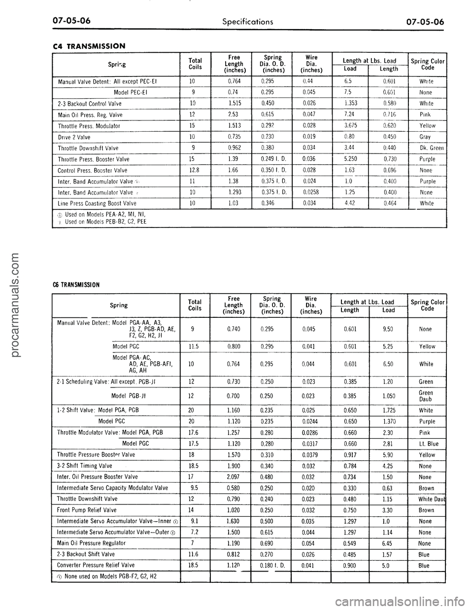
C4 TRANSMISSION
Spring
Manual Valve Detent: All except PEC-EI
Model PEC-EI
2-3 Backout Control Valve
Main Oil Press. Reg. Valve
Throttle Press. Modulator
Drive 2 Valve
Throttle Downshift Valve
Throttle Press. Booster Valve
Control Press. Booster Valve
Inter.
Band Accumulator Valve
.T,
Inter.
Band Accumulator Valve i
Line Press Coasting Boost Valve
Total
Coils
10
9
10
12
15
10
9
15
12.8
11
10
10
Free
Length
(inches)
0.764
0.74
1.515
2.53
1.513
0.735
0.962
1.39
1.66
1.38
1.293
1.03
Spring
Dia.
0. D.
(inches)
0.295
0.295
0.450
0.615
0.292
0.230
0.380
0.249
1. D.
0.350
1. D.
0.375
1. D.
0.375
1. D.
0.346
Wire
Dia.
(inches)
0.44
0.045
0.026
0.047
0.028
0.019
0.034
0.036
0.028
0.024
0.0258
0.034
Length
at Lbs.
Load
Load
6.5
7.5
1.353
7.24
3.675
0.80
3.44
5.250
1.63
1.0
1.25
4.42
Length
0.601
0.601
0.580
0.716
0.620
0.450
0.440
0.730
0.696
0.400
0.400
0.464
Spring Color
Code
White
None
White
Pink
Yellow
Gray
Dk. Green
Purple
None
Purple
None
White
® Used on Models PEA-A2, Ml, Nl,
'i.
Used on Models PEB-B2, C2, PEE
C6 TRANSMISSION
Spring
Manual Valve Detent: Model PGA-AA, A3,
J3,
Z, PGB-AD, AE,
F2, G2, H2,
Jl
Model PGC
Model PGA-AC,
AD,
AE, PGB-AFI,
AG,
AH
2-1 Scheduling Valve: All except, PGB-JI
Model PGB-JI
1-2 Shift Valve: Model PGA, PGB
Model PGC
Throttle Modulator Valve: Model PGA, PGB
Model PGC
Throttle Pressure Booster Valve
3-2 Shift Timing Valve
Inter.
Oil Pressure Booster Valve
Intermediate Servo Capacity Modulator Valve
Throttle Downshift Valve
Front Pump Relief Valve
Intermediate Servo Accumulator Valve—Inner ®
Intermediate Servo Accumulator Valve—Outer ©
Main Oil Pressure Regulator
2-3 Backout Shift Valve
Converter Pressure Relief Valve
cxy
None used on Models PGB-F2, G2, H2
Total
Coils
9
11.5
10
12
12
20
20
17.6
17.5
18
18.5
17
9.5
12
14
9.1
7.2
7
11.6
18.5
Free
Length
(inches)
0.740
0.800
0.764
0.730
0.700
1.160
1.120
1.257
1.120
1.570
1.900
2.097
0.580
0.790
1.020
1.630
1.500
1.190
0.812
1.120
Spring
Dia.
O. D.
(inches)
0.295
0.295
0.295
0.250
0.250
0.235
0.235
0.280
0.280
0.310
0.340
0.480
0.250
0.240
0.250
0.500
0.615
0.690
0.270
0.180
1.
D.
Wire
Dia.
(inches)
0.045
0.041
0.044
0.023
0.023
0.025
0.0244
0.0286
0.0317
0.0379
0.032
0.032
0.020
0.023
0.032
0.035
0.044
0.054
0.026
0.041
Length at Lbs. Load
Length
0.601
0.601
0.601
0.385
0.385
0.650
0.650
0.660
0.660
0.917
0.784
0.734
0.330
0.480
0.750
1.297
1.297
0.549
0.485
0.900
Load
9.50
5.25
6.50
1.20
1.050
1.725
1.370
2.30
2.81
5.90
4.25
1.50
0.63
1.15
3.30
1.0
1.14
6.45
1.57
5.0
Spring Color
Code
None
Yellow
White
Green
Green
Daub
White
Purple
Pink
Lt. Blue
Yellow
None
None
Brown
White Daul
Brown
None
None
None
Blue
Blueprocarmanuals.com
Page 407 of 413

07-05-07
Specifications
07-05-07
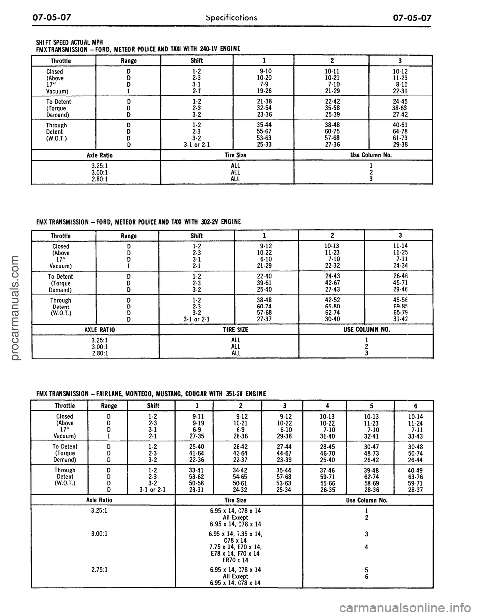
SHIFT SPEED ACTUAL
MPH
FMXTRANSMISSION -FORD, METEOR POLICE AND TAXI WITH 2401V ENGINE
Throttle
Closed
(Above
17"
Vacuum)
To Detent
(Torque
Demand)
Through
Detent
(W.O.T.)
Range
D
D
D
1
D
D
D
D
D
D
D
Axle Ratio
3.25:1
3.00:1
2.80:1
Shift
1-2
2-3
3-1
2-f
1-2
2-3
3-2
1-2
2-3
3-2
31
or 2-1
1
910
10-20
7-9
19-26
21-38
32-54
23-36
35-44
55-67
53-63
25-33
Tire Size
ALL
ALL
ALL
2
10-11
10-21
7-10
21-29
22-42
35-58
25-39
38-48
60-75
57-68
27-36
3
10-12
11-23
8-11
22-31
24-45
38-63
27-42
40-51
64-78
61-73
29-38
Use Column
No.
1
2
3
FMXTRANSMISSION -FORD, METEOR POLICE AND TAXI WITH 3022V ENGINE
Throttle
Closed
(Above
17"
Vacuum)
To Detent
(Torque
Demand)
Through
Detent
(W.O.T.)
Range
D
D
D
1
D
D
D
D
D
D
D
AXLE RATIO
3.25:1
3.00:1
2.80:1
Shift
1-2
2-3
3-1
2-1
1-2
2-3
3-2
1-2
2-3
3-2
3-1
or 21
1
9-12
10-22
6-10
21-29
22-40
39-61
25-40
38-48
60-74
57-68
27-37
TIRE SIZE
ALL
ALL
ALL
2
10-13
11-23
7-10
22-32
24-43
42-67
27-43
42-52
65-80
62-74
30-40
3
11-14
11-25
7-11
24-34
26-46
45-71
29-46
45-56
69-85
65-79
31-42
USE COLUMN
NO.
1
2
3
FMXTRANSMISSION
Throttle
Closed
(Above
17"
Vacuum)
To Detent
(Torque
Demand)
Through
Detent
(W.O.T.)
-FAIRLANE, MONTEGO, MUSTANG, COUGAR WITH 351-2V ENGINE
Range
D
D
D
1
D
D
D
D
D
D
D
Shift
1-2
2-3
3-1
21
1-2
2-3
3-2
1-2
2-3
3-2
3-1
or 2-1
Axle Ratio
3.25:1
3.00:1
2.75:1
1
9-11
9-19
6-9
27-35
25-40
41-64
22-36
33-41
53-62
50-58
23-31
2
9-12
10-21
6-9
28-36
26-42
42-64
22-37
34-42
54-65
50-61
24-32
3
9-12
10-22
6-10
29-38
27-44
44-67
23-39
35-44
57-68
53-63
25-34
Tire Size
6.95
x
14, C78 x
14
All Except
6.95
x
14, C78 x
14
6.95
x
14, 7.35
x 14,
C78 x
14
7.75
x
14, E70
x 14,
E78 x 14, F70 x
14
FR70
x 14
6.95 x 14, C78 x
14
All Except
6.95 x 14, C78 x
14
4
10-13
10-22
7-10
31-40
28-45
46-70
25-40
37-46
59-71
55-66
26-35
5
10-13
11-23
7-10
32-41
30-47
48-73
26-42
39-48
62-74
58-69
28-36
Use Column
No.
6
10-14
11-24
7-11
33-43
30-48
50-74
26-44
40-49
63-76
59-71
28-37
1
2
3
4
5
6procarmanuals.com
Page 408 of 413

07-05-08
Specifications
07-05-08
FMX TRANSMISSION
Throttle
Closed
(Above
17"
Vacuum)
To
Detent
(Torque
Demand)
Through
Detent
(W.O.T.)
-FAIRLANE,
1
Range
D
D
D
1
D
D
D
D
D
D
D
MONTEGO,
MUSTANG,
COUGAR
WITH 351-4V ENGINE
Shift
1-2
2-3
3-1
2-1
1-2
2-3
3-2
1-2
2-3
3-2
3-1 or 2-1
Axle Ratio
3.25:1
3.00:1
2.75:1
1
9-11
9-19
6-9
27-35
30-43
47-65
30-43
36-43
57-67
52-61
?5-33
2
9-12
10-21
6-9
28-36
30-45
49-68
30-45
38-46
59-70
54-65
26-35
3
9-12
10-22
6-10
29-38
32-47
51-71
32-47
40-48
62-74
57-68
27-36
Tire Size
6.95 x 14, C78 x
14
All
Except
6.95
x
14, C78
x
14
6.95
x
14. 7.35
x
14
C78
x
14
7.75
x
14, E70
x
14
E78
x
14, F70
x
14
FR70
x 14
6.95
x
14, C78
x
14
All
Except
6.95
x
14, C78
x
14
4
1013
10-22
7
31-.
33-49
53-74
33-49
41-50
65-76
59-70
28-37
5
10-13
11-23
7-10
32-41
35-50
56-76
35-50
43-51
68-79
62-72
30-39
6
10-14
11-24
7-11
33-43
36-53
57-79
36-53
44-53
69-82
63-75
30-40
Use
Column
No.
1
2
3
4
5
6
FMX TRANSMISSION -FORD, METEOR WITH 390-2V ENGINE
Throttle
Closed
(Above
18"
Vacuum)
To
Detent
(Torque
Demand)
Through
Detent
(W.O.T.)
Range
D
D
D
1
D
D
D
D
D
D
D
Shift
1-2
2-3
3-1
2-1
1-2
2-3
3-2
1-2
2-3
3-2
2-1 or 3-1
Axle Ratio
3.25:1
3.00:1
3.00:1
2.80:1
1
9-12
10-22
6-10
29-38
22-40
39-61
25-40
35-45
56-69
53-65
25-34
2
10-13
11-23
7-10
32-40
24-42
42-65
27-41
38-47
61-73
57-68
27-36
Tire Size
All
7.75x15
215R
x15
8.25 x
15
8.55
x
15
H70
x
15
All
3
10-13
11-23
7-10
32-42
24-43
42-67
27-43
39-49
62-75
58-70
27-37
4
11-14
11-25
7-11
34-45
26-46
45-71
29-46
41-53
65-80
61-75
29-40
Use
Column
No.
1
2
3
4procarmanuals.com