Page 49 of 413

02-02-30
Brake System
02-02-30
7.
Disconnect the wire lead at the
parking brake warning light switch
and remove the control assembly.
Installation
1.
Connect the wire lead to the
parking brake warning light switch.
2.
Position the control assembly to
the cowl inner side panel and install
the three attaching screws.
3.
Connect the ball-end of the park-
ing brake front cable assembly to the
control assembly, and install the hair-
pin retainer.
4.
Position the cable ball in the
notch in the brake clevis.
5.
Position the left air vent assem-
bly to the dash and instrument panels.
Install the four bolts and one nut re-
taining the air vent to the panels.
6. Check the operation of the park-
ing brake. Adjust the parking brake.
MUSTANG AND COUGAR
Removal
Refer to Fig. 36.
1.
Make sure the parking brake is
completely released,
2.
Remove all tension from the rear
cables by backing off the jam nut and
adjusting nut from the equalizer.
3.
Disconnect the wire lead at the
parking brake warning light switch (if
so equipped).
4.
Remove the parking brake front
cable ball retaining clip from the clev-
is.
5.
Remove the parking brake warn-
ing light switch and attaching screw (if
so equipped).
6. Disconnect the cable ball from
the notch in the brake clevis.
7.
Remove the three screws that at-
tach the control assembly to the left
cowl inner side panel.
8. Pull the control away from the
cowl, panel. Remove the hair-pin re-
tainer securing the front cable assem-
bly to the control assembly. Remove
the control assembly
Installation
1.
Connect the ball-end of the park-
ing brake front cable assembly to the
control assembly, and install the hair-
pin retainer.
2.
Position the control assembly to
the cowl inner side panel and install
the three attaching screws.
3.
Position the parking brake warn-
ing light switch and install the attach-
ing screw. Connect the parking brake
warning light switch wire lead (if vehi-
cle is so equipped).
4.
Position the cable ball in the
notch in the brake clevis.
5.
Check the operation of the park
ing brake. Adjust the parking brake.
THUNDERBIRD AND
CONTINENTAL MARK III
Removal
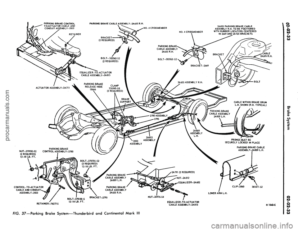
Refer to Fig. 37.
1.
Remove the two nuts retaining
the control to the dash panel.
2.
Remove two screws from the left
scuff plate.
3.
Remove one screw retaining the
left cowl trim panel and remove the
panel.
4.
Remove the two screws retaining
the left air duct and remove the air
duct.
5.
Remove the two screws retaining
the dimmer switch and position the
switch out of the way.
6. Remove the clip retaining the
cable assembly to the control.
7.
Disconnect the cable ball from
the control clevis.
8. Disconnect the vacuum hose at
the brake release.
9. Remove the bolt retaining the
control to the cowl side bracket and
remove the control.
Installation
1.
Position the parking brake con-
trol in the vehicle.
2.
Install the cable assembly in the
control and connect the cable ball to
the control clevis.
3.
Install the clip retaining the
cable to the control.
4.
Install the bolt retaining the con-
trol to the cowl side bracket.
5.
Connect the vacuum hose to the
parking brake release vacuum motor.
6. Position the dimmer switch and
install the retaining screws.
7.
Position the air duct and install
the retaining screws.
8. Position the cowl trim panel and
install the retaining screw.
9. Install the two scuff plate screws.
10.
Install the two nuts retaining
the control to the dash panel.
11.
Adjust the parking brakf
LINCOLN CONTINENTAL
Removal
Refer to Fig. 38.
1.
Raise the vehicle on a hoist.
2.
Loosen the parking brake cable
adjusting nut, remove the return
spring and remove the cable ball end
from the equalizer.
3.
Lower the vehicle.
4.
Disconnect the battery.
5.
Disconnect the wire harness con-
nector and two vacuum hoses at the
Automatic Temperature Control box.
6. Working inside the vehicle, re-
move the windshield wiper control
knob and bezel from the lower control
panel.
7.
Remove the screws retaining the
lower control panel. Lower the control
panel and disconnect wire harnesses
and vacuum hoses. Position the con-
trol panel aside.
8. Remove the screw retaining the
plastic wire cover and place 'the cover
aside.
9. Disconnect three vacuum hoses
and the wiring harness at the Auto-
matic Temperature Control box.
10.
Remove the two screws retain-
ing the Automatic Temperature Con-
trol box to the dash panel and remove
the box for clearance.
11.
Disconnect the ball end of the
cable from the control clevis.
12.
Remove the four bolts retaining
the control to the dash panel and
lower instrument panel flange.
13.
Disconnect the vacuum release
hose from the control and remove the
control assembly from the vehicle.
Installation
1.
Position the control assembly to
the dash panel and instrument panel
flange and install the four retaining
screws.
2.
Connect the vacuum release hose
to the control assembly.
3.
Connect the cable ball to the
control clevis.
4.
Position the Automatic Temper-
ature Control box to the dash panel
and install the retaining screws.
5.
Connect the wiring harness and
vacuum hoses to the Automatic Tem-
perature Control box.
6. Position the plastic wire covei
and install the retaining screw.
7.
Connect the wire harnesses and
vacuum lines to the lower control
panel and position the panel to the inprocarmanuals.com
Page 50 of 413
CABLE ASSEMBLY
2A635 R.H.
DUAL EXHAUST
PRONGS MUST BE SECURELY
LOCKED IN PLACE
EXTENSION SIDE MEMBER
EQUALIZER
2A602
VIEW IN CIRCLE R
TYPICAL 2 PLACES
CONVERTIBLE ONLY
VIEWY
VIEWZ
HI646-A
36—Parking Brake System—Mustang and Cougarprocarmanuals.com
Page 51 of 413
BOLT
2-REQUIRED
PARKING BRAKE
CONTROL ASSEMBLY
2780
2.00 ARMOR
I
A RKING
RRAKE
HONT CABLE-2853
ADJUSTING NUT
EQUALIZER-2A602
2628
CLIP
VIEWY 2A814 ASSEMBLY
BOLT-2 REQUIRED 2A706
2853 ASSEMBLY
PARKING BRAKE REAR
CABLE-2A635 2 REQUIRED
BRACKET-2A813
SCREW
4 REQUIRED
VIEWZ
8~-
VIEWX
HAIRPIN RETAINER-74277-S
PARKING BRAKE FRONT CABLE-2853
BOLT-374032-S 2 REQUIRED
7-12 LB. FT. APPLY CAULKING CORD
(AB19560-A) OVER HEADS OF SCREWS
AFTER ASSEMBLY.
WIRING HARNESS
HOSE
BRAKE SUPPORT
PARKING BRAKE
REAR CABLE-2A635
PARKING BRAKE
REAR CABLE-2A635
PARKING BRAKE
REAR CABLE-2A635
HAIRPIN RETAINER
( 2 REQUIRED
V1EWW
PARKING BRAKE
REAR CABLE-2A635
CLIP 2 REQUIRED
PRONGS MUST BE SECURELY
LOCKED IN PLACE
VtEWU
BOLT 2 REQUIRED
VIEWY
VIEWT
CABLE WllHIN BRAKE DRUM
H 1529-B
FIG. 38
Parking Brake System—Lincoln Continentalprocarmanuals.com
Page 52 of 413

PARKING BRAKE CONTROL
TO-ACTUATOR CABLE AND
CONDUIT ASSEMBLY-2853
PARKING BRAKE CABLE ASSEMBLY-2A635 R.H.
2A635 PARKING BRAKE CABLE
ASSEMBLY R.H. TO BE POSITIONED
WITH RUBBER LOCATERS CENTERED
IN 2649 AND
2A 720
BRACKETS
NO.
4 CROSSMEMBER
NO.
4 CROSSMEMBER
BRACKET
(2 REQUIRED)
PARKING BRAKE
CABLE ASSEMBLY
2A635 R.H.
BOLT-382062-S2
(2 REQUIRED)
EQUALIZER.TO-ACTUATOR
CABLE ASSEMBLY-2A815
2A635 ASSEMBLY R.H.
ACTUATOR ASSEMBLY-2A7U
CABLE WITHIN BRAKE DRUM
L.H. SHOWN (R.H. TYPICAL)
PARKING BRAKE
CABLE ASSEMBLY
2A809 UH.
2780 ASSEMBLY
2795
2A809
ASSEMBLY
L.H.
PRONGS MUST BE
SECURELY LOCKED IN PLACE
PARKING BRAKE CABLE
ASSEMBLY-2A809 L.H.
PARKING BRAKE
CONTROL ASSEMBLY-2780
BOLT-378735-S2
(2 REQUIRED)
LB.
FT.
2A791 (2 REQUIRED)
PARKING BRAKE
CABLE ASSEMBLY
2A809 L.H.
NUT-2A812
EQUALIZER-2A602
PARKING BRAKE
CABLE ASSEMBLY
2A635 R.H.
NUT-379930-S2
(2 REQUIRED)
12-18 LB. FT.
CONTROL-TO-ACTUATOR
CABLE AND CONDUIT
ASSEMBLY-2853
381877-S2
RETAINER-74277-S
BOLT-378180-S
12-18 LB. FT.
EQUALIZER.TO-ACTUATOR
CABLE ASSEMBLY-2A815
H1542-C
FIG. 37—Parking Brake System—Thunderbird and Continental Mark IIIprocarmanuals.com
Page 53 of 413

02-02-34
Brake System
02-02-34
strument panel. Install the lower con-
trol panel retaining screws.
8. Install the windshield wiper con-
trol bezel and knob.
9. Working in the engine compart-
ment connect the wire harness and
vacuum hoses to the Automatic Tem-
perature Control box.
10.
Connect the battery cable.
11.
Raise the vehicle on a hoist.
12.
Connect the cable ball to the
equalizer and install the equalizer
lever return ^spring.
13.
Adjust the parking brake cable
tension.
14.
Lower the vehicle.
PARKING BRAKE ACTUATOR—
TO CONTROL CABLE
FORD, MERCURY
AND METEOR
Removed
1.
Raise the vehicle on a hoist.
2.
Loosen the actuator lever to
equalizer cable adjusting nut at the
equalizer (Fig. 34).
3.
Disconnect the cable ball from
the clevis on the actuator lever.
4.
Remove spring clip that retains
the cable to the frame.
5.
From inside of passenger com-
partment, remove spring clip that re-
tains the cable to the parking brake
control. Disconnect the cable ball
from the control assembly.
6. Remove the cable assembly from
the vehicle.
Installation
1.
Position the cable through the
provided openings and in the approxi-
mate final installation position.
2.
Install the hairpin retainer on the
cable at the frame crossmember.
3.
Connect the ball end of the cable
to the parking brake control. Install
the cable-to-control hairpin retaining
clip.
4.
Position the cable seal at the
dash panel, and slide the retaining clip
upward to seal the cable at the dash
opening.
5.
Connect the ball end of the cable
to the clevis on the actuator lever.
6. Adjust the parking brake (Part
2-1,
Section 2).
7.
Lower vehicle on hoist.
THUNDERBIRD AND
CONTINENTAL MARK III
Removal
Refer to Fig. 37.
1.
Partially raise the vehicle.
2.
Back off the adjusting nut at the
equalizer to relieve the tension on the
cable.
3.
Remove the spring at the actua-
tor lever and disconnect the control
cable from the clevis on the lever.
4.
Remove the clip retaining the
control cable assembly to
thq*.
frame
bracket. B
5.
Attach a length of wire to the
control cable.
6. Working inside the vehicle re-
move two screws retaining the left
scuff plate.
7.
Remove one screw and remove
the left cowl side trim panel.
8. Remove the two screws retaining
the left air duct to the inner panel and
remove the air duct.
9. Remove the two screws retaining
the dimmer switch and position the
dimmer switch back out of the way.
10.
Remove the clip retaining the
cable assembly to the control and re-
move the cable ball from the control
clevis.
11.
Pull the cable up through the
opening in the dash panel and remove
the cable from the length of wire.
Installation
1.
Attach the cable to the length of
wire and pull the cable down through
the opening in the dash panel.
2.
Position the upper end of the
control cable to the control. Connect
the cable ball to the control clevis and
install the clip retaining the cable
housing to the control.
3.
Remove the length of wire from
the cable assembly and position the
cable in the frame bracket. Install the
retainer,
4.
Connect the cable ball to the
clevis on the actuator lever and install
the actuator lever spring.
5.
Adjust the parking brake.
6. Reposition the dimmer switch
and install the retaining screws.
7.
Position the air duct to the inner
panel and install the retaining screws.
& Position the cowl side trim panel
and install the retaining screw.
9. Install the two screws in the
scuff plate.
PARKING BRAKE
EQUALIZER TO CONTROL
CABLE
FAIRLANE, MONTEGO
AND FALCON
Removal
Refer to Fig. 35.
1.
Make certain the parking brake
is fully released.
2.
Raise the vehicle on a hoist. Re-
move the two nuts that attach the
cable to the equalizer. Remove the
equalizer, spring seat and spring.
3.
Remove the hairpin retainer
holding the cable assembly to i:he body
bracket and remove the cable from
the slot in the bracket.
4.
Lower the vehicle partially.
5.
Remove the hairpin retainer
which retains the cable assembly to
the control.
6. Remove the cable bolt retaining
clip from the control clevis and dis-
connect the cable ball from the clevis.
7.
Pull the cable down through the
opening in the floor pan and frame
side rail.
Installation
1.
Route the new cable through
the frame side rail and up through
the opening in the floor pan. Pull the
cable up into position.
2.
Connect the cable ball in the con-
trol clevis.
3.
Insert the cable housing into
the control and install the hairpin re-
tainer.
4.
Raise the vehicle.
5.
Position the cable in the body
bracket and install the hairpin re-
tainer.
6. Position the spring, spring re-
tainer and equalizer on the cable and
install the two nuts.
7.
Adjust the parking brake.
MUSTANG AND COUGAR
Removal
Refer to Fig. 36.
1.
Make certain the parking brake
is fully released.
2.
Raise the vehicle on a hoist. Re-
move the two nuts that attach the
cable to the equalizer. Remove the
equalizer spring seat and spring.
3.
Remove the hairpin retainer
holding the cable assembly to the
body bracket and pull the cable out
of the side rail access holes.procarmanuals.com
Page 54 of 413

02-02-35
Brake System
02-02-35
4.
Attach a wire to the end of the
cable to assist in routing new cable.
5.
Lower the vehicle.
6. Remove the parking brake front
cable ball retaining clip from the
clevis.
7.
Disconnect the cable ball from
the notch in the brake clevis.
8.. Remove the hairpin retainer and
remove the cable assembly from the
brake control assembly.
9. Pull the cable assembly up through
the opening in the floor and remove
the wire from the end of the cable.
Installation
Refer to Fig. 36.
1.
Connect the wire to the end of
the cable assembly and pull the cable
down through the opening in the
floor. Remove the wire.
2.
Connect the cable assembly to
the brake control assembly and in-
stall the hairpin retainer.
3.
Position the ball end of the
cable in the notch of the brake clevis.
4.
Raise the vehicle on a hoist.
5.
Pull the cable grommet into po-
sition and route the cable through
the access holes in the side rail and
under the fuel line.
6. Insert the cable into the body
bracket and install the hairpin re-
tainer.
7.
Position the spring, spring seat,
and equalizer on the cable and install
the two nuts.
8. Adjust the parking brake.
LINCOLN CONTINENTAL
Removal
1.
Raise the car on a hoist. Dis-
connect the parking brake cable from
the equalizer lever underneath the
car (Fig. 38).
2.
Remove the retaining clip at the
cable bracket, and disengage the cable
from the bracket (Fig. 38).
3.
Remove the supporting clip re-
taining bolts and remove the support
plate from the underbody.
4.
Lower the car on a hoist.
5.
With the parking brake in the
fully released position, disconnect the
cable at the control assembly.
6. Raise the vehicle on a hoist. Re-
move the left front fender apron
splash shield retaining bolts and the
splash shield.
7.
Remove the two bolts securing
the parking brake control to equaliz-
er cable bracket to the dash panel
and remove the cable from the vehicle.
Installation
1.
Route the parking brake control
to equalizer cable to the control as-
sembly and the equalizer, and install
the two bolts that retain the cable
to the dash panel (Fig. 38).
2.
Install the left fror%/ender apron
splash shield and the ^u attaching
bolts.
3.
Lower the vehicle.
4.
Connect the control cable to the
clevis on the control assembly.
5.
Raise the car on a hoist.
6. Position the supporting clip and
cable on the vehicle and install the
retaining bolts. Do not tighten the
bolts.
Position the cable armor ap-
proximately 1/2 inch to the right of
the clip (looking toward the rear of
the car) and tighten the retaining
bolts.
7.
Position the equalizer control
cable to the support bracket and in-
stall the retaining hairpin clip.
8. Connect the ball end of the con-
trol cable to the equalizer lever.
9. Adjust the parking brake linkage
(Part
2-1,
Section 2).
10.
Check the operation of the auto-
matic release mechanism.
PARKING BRAKE
ACTUATOR-TO-EQUALIZER
CABLE
FORD, MERCURY,
METEOR, THUNDERBIRD
AND CONTINENTAL
MARK III
Removal
Refer to Figs. 34 and 37.
1.
Raise the vehicle on a hoist.
2.
Remove the lock and adjusting
nut which retains the cable to the
equalizer.
3.
Remove the cable end from the
equalizer.
4.
Unhook the cable from the act-
uator, and remove from the vehicle. *
Installation
1.
Insert new cable end into act-
uator.
2.
Insert cable end into equalizer
and tighten the adjusting nut snug.
Install the lock nut.
3.
Adjust the parking brake cable
tension and check operation as out-
lined in Part
2-1,
Section 2.
4.
Lower the vehicle.
PARKING BRAKE EQUALIZER
TO REAR WHEEL CABLE
FORD, MERCURY,
METEOR, THUNDERBIRD
AND CONTINENTAL
MARK III
Removal
1.
Raise the vehicle and tffosen the
parking brake equalizer rod" adjusting
nut. Disconnect the equalizer from the
rear cables (Figs. 34 and 37).
2.
Compress the prongs on the left
cable-to-frame side member retainer
so the prong can pass through the
side-member. Remove the clip that at-
taches the left cable to the left lower
arm. Pull the cable thru the frame left
side member.
3.
Compress the prongs on the
right cable-to-frame side member re-
tainer bracket so the prong can pass
through the bracket. Remove the clips
retaining the right cable to the frame
crossmember.
4.
Remove the rear wheel cover and
wheel. Remove the three Tinnerman
nuts that hold the brake drum in place
and remove the drum.
5.
Working on the wheel side of the
rear brake, remove the automatic
brake adjuster spring. Compress the
prongs on the parking brake cable re-
tainer so that they can pass through
the hole in the brake backing plate.
Draw the cable retainer through the
hole.
6. With the spring tension off the
parking brake lever, lift the cable out
of the slot in the lever and remove the
cable through the backing plate hole.
Installation
1.
Pull enough of the parking brake
cable through the housing so that the
end of the cable may be inserted over
the slot in the parking brake lever on
the rear brake shoe.
2.
Pull the excess slack from the
cable, and insert the cable housing
into the brake backing plate access
hole so that the retainer prongs ex-
pand. The prongs must be securely
locked in place. Install the automatic
brake adjuster spring.
3.
Position the right hand cable and
the two retaining clips and screws on
the rear crossmember. Compress the
prongs on the right cable and position
the cable in the retaining bracket on
the frame side member. Be sure theprocarmanuals.com
Page 55 of 413

02-02-36
Brake System
02-02-36
locating stripe on the cable is midway
between the retaining clips and tighten
all retaining clip screws.
4.
Position the left cable, retaining
clip and screw on the left lower sus-
pension arm. Compress the prongs on
the left cable and position the cable
through the frame side-member. The
prongs must be securely locked in
place.
5.
Insert the ball ends of the cables
into the equalizer assembly.
6. Install the rear drum(s) and
tighten the three Tinnerman nuts and
secure the drum. Install the wheel and
tire and the wheel cover.
7.
Adjust the parking brake linkage
as outlined in Part 2-1, Section 2. Ad-
just the rear brakes, as required (Part
2-1,
Section 2).
FAIRLANE, MONTEGO,
MUSTANG AND COUGAR—
EXCEPT STATION WAGON
Removal
1.
Remove the equalizer lock nut
and adjusting nut, equalizer, spring
and spring seat.
2.
With the cables slack, discon-
nect the ball-ends from the connector
(Figs.
35 and 36).
3.
Remove the cable from the re-
tainer hooks (station wagon models)
and the underbody guide (convertible
models) if required.
4.
Remove the hairpin lock retain-
ing the cable housing to the side rail
bracket.
5.
Remove the wheel cover, wheel
and tire and the rear brake drum as
outlined in Section 2.
6. Remove self-adjuster springs to
allow clearance to remove cable re-
tainer from the backing plate. Discon-
nect the rear end of the cable from the
parking brake lever on the brake shoe.
Disengage the cable housing retaining
grommet or steel-pronged Hi-Hat
from the backing plate and withdraw
the cable and housing from the in-
board side of the backing plate.
7.
Slide the cable and housing out
of the side rail bracket.
Installation
1.
Insert the rear end of the cable
through the side rail bracket and pull
the cable and housing into position.
2.
Insert the rear end of the cable
and housing through the hole in the
backing plate from the inboard side.
3.
Connect the cable to the parking
brake lever on the brake shoe and in-
stall the cable housing retaining grom-
met or steel-pronged Hi-Hat in the
backing plate.
4.
Install the self-adjuster springs.
Position the cable housing in the side
rail bracket and install the hairpin
type retainer.
5.
Install rear hub and drum as-
sembly, wheel and tire assemblies and
wheel cover as outlined in Section 2.
6. Position the cable retainer hooks
(station wagon models) in the under-
body guide (convertible models) and
install the connector, thus hooking the
two cables together.
7.
Insert the cable into the equaliz-
er and install the equalizer, spring
seat, spring, adjusting nut and lock
nut to the front, parking brake control
cable.
8. Adjust the parking brake^as di-
rected in Part 2-1, Section 2.
FAIRLANE AND MONTEGO
STATION WAGONS AND
FALCON PASSENGER
MODELS
Removal and Installation
Refer to Fig. 35.
Generally follow the procedure
given above, omitting separation of
the cables, since the parking brake
rear cable assemblies supplied for
these models is in one piece. Removal
and installation of both rear wheels,
tires and drums will also be required.
LINCOLN CONTINENTAL
Removal
1.
Raise the car. Remove the rear
wheel cover. Remove the wheel and
tire as an assembly.
2.
Remove the three Tinnerman
nuts that hold the brake drum in
place, and remove the drum.
3.
Remove the brake shoe retract-
ing springs.
4.
Loosen the equalizer rod adjust-
ing nut and disconnect the cable from
the equalizer (Fig. 38).
5.
Remove the hairpin-type retainer
clip that secures the cable housing to
the body bracket, and pull the cable
and housing out of the bracket (Fig.
38).
6. Remove the cable to underbody
clamp attaching nuts and the clamp.
Disengage the cable housing from the
hook-type retainer at the spring U-
bolt.
7.
Working on the wheel side of the
backing plate (Fig. 38), compress the
prongs on the cable retainer so that it
can pass through the hole in the back-
ing plate. Draw the cable retainer out
of the hole.
8. With the spring tension off the
parking brake lever, lift the cable out
of the slot in the lever and remove it
through the backing plate hols.
Installation
1.
Pull enough of the cable through
the cable housing so that the end of
the cable may be inserted through the
backing plate hole from the inner side
and engage the cable end with the slot
in the parking brake lever.
2.
Pull the excess slack from the
cable and insert the cable housing into
the backing plate access hole (Fig.
38).
The prongs must be securely
locked in place.
3.
Install the brake shoe retracting
springs.
4.
Position the cable to the under-
body and install the retaining clamp
so that the cable conduit armor ex-
tends forward of the clamp as shown
in Fig. 38. Install the clamp retaining
nuts.
5.
Hook the cable housing to the
retainer at the spring U-bolt.
6. Engage the forward end of the
cable housing with the frame bracket
and secure it with the hairpin-type
clip.
7.
Insert the ball end of the cable
into the equalizer.
8. Make a preliminary brake ad-
justment with the use of Tool HRA-
8650 (Fig. 11).
9. Install the rear drum. Tighten
the three Tinnerman nuts that secure
the drum. Install the wheel and wheel
cover.
10.
Adjust the parking brake link-
age.
11.
Lower the vehicle.
ANTI-SKID CONTROL
ACTUATOR
REMOVAL
Refer to Fig. 39.
1.
Working in the passenger com-
partment, under the glove box, remove
the screw that attaches the forward
end of the control module retainer to
the support assembly. Lower the for-
ward end of the control module re-
tainer and remove the module assem-
bly.procarmanuals.com
Page 56 of 413
FROM MASTER CYLINDER
ACTUATOR AIR FILTER
EXISTING SCREW
VIEW IN CIRCLE
W
SOLENOID
ACTUATOR TO REA
BRAKE TUBE
DIFFERENTIAL VALVE
UATORTUBE
VIEW IN CIRCLE T
FROM ACTUATOR
TO REAR BRAKES
GLOVE BOX
CONTROL MODULE
VIEW V
VIEW U
H1653-A
FIG. 39—Anti-Skid Control Systemprocarmanuals.com