Page 177 of 413

03-12-06
Wheels And Tires
03-12-06
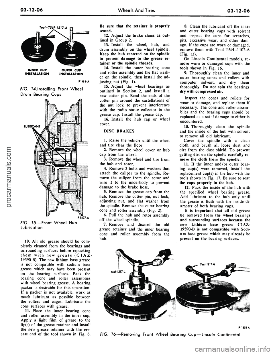
Tool-T56P-1217-A
INNER CUP
INSTALLATION
OUTER CUP
INSTALLATION
F1464-A
FIG. ^.Installing Front Wheel
Drum Bearing Cups
LUBR
F1427. A
FIG. 75—Front Wheel Hub
Lubrication
10.
All old grease should be com-
pletely cleaned from the bearings and
surrounding surfaces before repacking
them with new grease (C1AZ-
19590-B). The new lithium base grease
is not compatible with sodium base
grease which may have been present
on the bearing surfaces. Pack the
bearing cone and roller assemblies
with wheel bearing grease. A bearing
packer is desirable for this operation.
If a packer is not available, work as
much lubricant as possible between
the rollers and cages. Lubricate the
cone surfaces with grease.
11.
Place the inner bearing cone
and roller assembly in the inner cup,
Apply a light film of grease to the
lip(s) of the grease retainer and install
the new grease retainer with the rev-
erse end of the tool shown in Fig. 6.
Be sure that the retainer is properly
seated.
12.
Adjust the brake shoes as out-
lined in Group 2.
13.
Install the wheel, hub, and
drum assembly on the wheel spindle.
Keep the hub centered on the spindle
to prevent damage to the grease re-
tainer or the spindle threads.
14.
Install the outer bearing cone
and roller assembly and the flat wash-
er on the spindle, then install the ad-
justing nut (Fig. 1).
15.
Adjust the wheel bearings as
outlined in Section 2, and install a
new cotter pin. Bend the ends of the
cotter pin around the castellations of
the nut lock to prevent interference
with the radio static collector in the
grease cap. Install the grease cap.
16.
Install the hub cap or wheel
cover.
DISC BRAKES
1.
Raise the vehicle until the wheel
and tire clear the floor.
2.
Remove the wheel cover or hub
cap from the wheel.
3.
Remove the wheel and tire from
the hub and rotor.
4.
Remove 2 bolts and washers that
attach the caliper to the spindle. Re-
move the caliper from the rotor and
wire it to the underbody to prevent
damage to the brake hose.
5.
Remove the grease cap from the
hub.
Remove the cotter pin, nut lock,
adjusting nut, and flat washer from
the spindle. Remove the outer bearing
cone and roller assembly (Fig. 2).
6. Pull the hub and rotor assembly
off the wheel spindle.
7.
Remove and discard the old
grease retainer and the inner bearing
cone and roller assembly from the
hub.
8. Clean the lubricant off the inner
and outer bearing cups with solvent
and inspect the cups for scratches,
pits,
excessive wear, and other dam-
age.
If the cups are worn or damaged,
remove them with Tool T69L-1102-A
(Fig. 13).
On Lincoln Continental models, re-
move worn or damaged cups with the
tools shown in Fig. 16.
9. Thoroughly clean the inner and
outer bearing cones and rollers with
computer solvent, and dry them
thoroughly. Do not spin the bearings
dry with compressed air.
Inspect the cones and rollers for
wear or damage, and replace them if
necessary. The cone and roller assem-
blies and the bearing cups should be
replaced as a set if damage to either is
encountered.
10.
Thoroughly clean the spindle
and the inside of the hub with solvent
to remove all old lubricant.
Cover the spindle with a clean
cloth, and brush all loose dust and
dirt from the dust shield. To prevent
getting dirt on the spindle carefully re-
move the cloth from the spindle.
11.
If the inner and/or outer bear-
ing cup(s) were removed, install the
replacement cup(s) in the hub with the
tools shown in Fig. 17. Be sure to seat
the cups properly in the hub.
12.
Pack the inside of the hub with
the specified wheel bearing grease.
Add lubricant to the hub only until
the grease is flush with the inside di-
ameter of both bearing cups.
It is important that all old grease
be removed from the wheel bearings
and surrounding surfaces because the
new Lithium base grease C1AZ-
19590-B is not compatible with Sodi-
um base grease which may already be
present on the bearing surfaces.
F 1502-A
FIG. 16—Removing Front Wheel Bearing Cup—Lincoln Continentalprocarmanuals.com
Page 178 of 413

03-12-07
Wheels And Tires
03-12-07
Tool - 7277- K
F 1263-A
FIG. 17—Installing Front Wheel Bearing Cup
13.
Pack the bearing cone and roll-
er assemblies with wheel bearing
grease. A bearing packer is desirable
for this operation. If a packer is not
available, work as much lubricant as
possible between the rollers and cages.
Lubricate the cone surfaces with
grease.
14.
Place the inner bearing cone
and roller assembly in the inner cup.
Apply a light film of grease to the lips
of the grease retainer and install the
new grease retainer with the tool
shown in Fig. 18. Be sure the retainer
is properly seated.
15.
Install the hub and rotor as-
sembly on the wheel spindle. Keep the
hub centered on the spindle to prevent
damage to the grease retainer or the
spindle threads.
16.
Install the outer bearing cone
and roller assembly and the flat wash-
er on the spindle, then install the ad-
justing nut.
17.
Adjust the wheel bearings as
outlined in Section 2, and install a
new cotter pin. Bend the ends of the
cotter pin around the castellations of
the nut lock to prevent interference
with the radio static collector in the
grease cap. Install the grease cap.
18.
Install the caliper to the spindle
and torque the attaching bolts to spe-
cifications as detailed in Group 2.
19.
Install the wheel and tire on the
hub.
20.
Install the hub cap or wheel
cover.
21.
Before driving the vehicle,
pump the brake pedal several times to
obtain normal brake lining to rotor
clearance and restore normal brake
pedal travel.
FRONT HUB AND DRUM
ASSEMBLY REPLACEMENT
When the hub and drum assembly
is replaced, new bearings and a grease
retainer must be installed in the new
assembly. The new grease retainer
should be soaked in light engine oil at
least 30 minutes before installation.
1.
Raise the vehicle until the wheel
and tire clears the floor. Pry off the
hub cap or wheel cover, and remove
the wheel and tire from the hub and
drum assembly.
2.
Remove the grease cap from the
hub.
Remove the cotter pin, nut lock
adjusting nut, and flat washer from
the spindle. Remove the outer bearing
cone and roller assembly (Fig. 1).
3.
Pull the hub and drum assembly
off the wheel spindle.
4.
Remuve the grease retainer and
the inner bearing cone and roller as-
sembly from the hub with Tool
1175AE.
5.
Remove the protective coating
from the new hub and drum with car-
buretor degreaser.
6. Pack the inside of the hub with
specified wheel bearing grease. Add
lubricant to the hub only until the
grease is flush with the inside diame-
ter of both bearing cups (Fig. 15).
7.
All old grease should be com-
pletely cleaned from the bearings be-
fore repacking them with new grease.
Pack the bearing cone and roller
assemblies with wheel bearing grease.
A bearing packer is desirable for this
operation. If a packer is not available,
work as much lubricant as possible
between the rollers and cages. Lubri-
cate the cone surfaces with grease.
8. Place the inner bearing cone and
roller assembly in the inner cup, and
install the new grease retainer with the
reverse end of the tool shown in Fig.
6. Be sure that the retainer is properly
seated.
9. Adjust the brake shoes as out-
lined in Group 2.
10.
Install the new hub and drum
assembly on the wheel spindle. Keep
the hub centered on the spindle to pre-
vent damage to the grease retainer.
11.
Install the outer bearing cone
and roller assembly and the flat wash-
er on the spindle; then, install the ad-
justing nut (Fig. 1).
12.
Position the wheel and tire on
the new hub and drum assembly. In-
stall the wheel hub nuts and tighten
them alternately in order to draw the
wheel evenly against the hub and
drum.
13.
Adjust the wheel bearings as
outlined in Section 2, and install a
new cotter pin. Bend the ends of the
cotter pin around the castellations of
the nut lock to prevent interference
with the radio static collector in the
grease cap. Install the grease cap.
14.
Install the hub cap or wheel
cover.
FRONT HUB AND ROTOR
ASSEMBLY REPLACEMENT
When the hub and rotor assembly is
replaced, new bearings and a grease
retainer must be installed in the new
assembly.
1.
Raise the vehicle until the wheel
and tire clear the floor. Pry off the
hub cap or wheel cover, and remove
the wheel and tire from the hub and
rotor assembly.
2.
Remove 2 bolts and washers that
attach the caliper to the spindle. Re-
move the caliper from the rotor and
wire it to the underbody to prevent
damage to the brake hose.
3.
Remove the grease cap from the
hub.
Remove the cotter pin, nut lock,
adjusting nut, and flat washer from
the spindle; then, remove the outer
bearing cone and roller assembly,
(Fig. 2).
4.
Pull the hub and rotor off the
spindle.
5.
Remove the protective coating
from the new hub and rotor with car-
buretor degreaser.
6. Grease and install the inner
bearing cone and roller assembly in
the inner bearing cup. Apply a light
film of grease on the grease retainerprocarmanuals.com
Page 179 of 413

03-12-08
Wheels And Tires
03-12-08
Tool -
7
775 - AH
F1443-A
FIG.
18
— Installing Grease
Retainer
and install the grease retainer.
7.
Install the new hub and rotor as-
sembly to the wheel spindle. Keep the
hub centered on the spindle to prevent
damage to the grease retainer.
8. Install the outer bearing cone
and roller assembly and the flat wash-
er on the spindle; then, install the ad-
justing nut.
9. Install the caliper to the spindle
and tighten the attaching bolts to spe-
cifications as detailed in Group 2.
10.
Position the wheel and tire on
the new hub and rotor. Install the
wheel hub nuts and tighten them alter-
nately in order to draw the wheel
evenly against the hub and rotor.
11.
Adjust the wheel bearings as
outlined in Section 2, and install a
new cotter pin. Bend the ends of the
cotter pin around the castellations of
the nut lock to prevent interference
with the radio static collector in the
grease cap. Install the grease cap.
12.
Install the hub cap or wheel
cover.
13.
Before driving the vehicle,
pump the brake pedal several times to
obtain normal brake lining to rotor
clearance and restore normal brake
pedal travel.
LIFE GUARD
TIRE REPAIRS
REPAIR OF OUTER TIRE
Outside Repairs
All outside repairs are made in the
same manner as on conventional tube-
less tires.
Inside Repairs
1.
Remove the anti-friction treat-
ment on the inside of the tire with
rubber solvent.
2.
Buff the inside area of the tire.
3.
Apply a hot cure patch only.
REPAIR OF AIR
CONTAINER
Air containers are repaired in the
same manner as conventional inner
tubes.
REPAIR OF LIFE GUARD
A damaged life guard that may
pinch the air container should be re-
place. No repairs are required for
small punctures in the life guard.procarmanuals.com
Page 180 of 413

03-13-01
Specifications
03-13-01
PART 3-13 Specifications
FRONT
WHEEL
ALIGNMENT
Vehicle
Model
Mustang,
Cougar
Fairlane, Falcon
Mont
ego
Ford,
Mercury
Meteor
Thunderbird,
Mark III
Lincoln
Continental
Dimension
"C"
Inches
(I) 6.30
® 6.50
©4.20
® 4.20
©5.87
Dimension
"D"
Inches
©5.50 (Mustang)
6.35 (Cougar)
©6.72
©6.70
©6.70
©8.39
Alignment
Factors
Caster©
Camber©
Toe-in-Inches
Caster©
Camber©
Toe-in-Inches
Caster©
Camber©
Toe-in-Inches
Caster©
Camber®
Toe-in-Inches
Caster®
Camber®
Toe-in-Inches
Min.
-3/4°
+1/4°
1/16
-1
3/4°
•1/2°
1/8
0°
•1/4°
1/16
0°
•1/4°
1/16
-1/2°
•1/4°
0
Max.
+1 1/4°
+1 3/4°
5/16
+1/4°
+1°
3/8
+2°
+11/4°
5/16
+2°
+1 1/4°
5/16
-2
1/2°
+11/4°
1/4
Desired
+1/4°
+3/4°
3/16
•3/4°
+1/4°
3/16
+1°
+1/2°
3/16
+1°
+1/2°
3/16
•11/2°
+1/2°
1/8
©Maximum difference between wheels not to exceed 1/2° (setting). Maximum checking difference not to exceed 1° with caster and camber
with-
in specifications.
©Maximum difference between wheels not to exceed 1/2°.
©Vertical distance between bottom surface of spring tower on centerline of rebound bumper bolt and point on flat surface of upper suspension
arm midway between ball joint rivets.
©Shortest vertical distance between point on side member and axle housing.
©Distance from corner of lower flange sidemember front to center of bolt head (strut mounting bolt).
©Vertical distance between bottom of sidemember at center of axle bumper bracket and top of axle housing.
©Vertical distance between point on underside of crossmember pocket and point on top of drag strut.
©Distance from axle housing to surface on sidemember immediatly behind axle bumper.
WHEELBASEAND TREAD WIDTH-INCHES
FRONT WHEEL TURNING ANGLE
Vehicle Model
Mustang
Cougar
Fairlane, Montego
Falcon (except Station Wagon)
Falcon Station Wagon
Ford
Mercury, Meteor
Thunderbird (2-Door)
Thunderbird (4-Door), Mark HI
Lincoln Continental
Wheelbase
108.0
111.1
116.0
110.9
113.0
121.0
124.0
114.7
117.2
126.0
Tread
Front
58.5
58.5
58.8
58.8
58.8
63.0
63.0
62.0
62.0
62.4
Width
Rear
58.5
58.5
5«.5
58.5
58.5
64.0
64.0
62.0
62.0
61.0
Vehicle Model
Mustang,
Cougar
Fairlane, Falcon, Montego
Ford,
Mercury, Meteor
Thunderbird, Mark III
Lincoln Continental
Turning Angle of Outside Wheel
With Inside Wheel Turned 20°
18.68°
With Power Steering 17.88°
With Manual Steering 18.1°
With Power Steering 19.14°
With Manual Steering 18.96°
19.26°
17.71°
BALL JOINTS -RADIAL PLAY
STEERING WHEEL TURNING EFFORT
Vehicle Model
Cougar, Fairlane,
Falcon,
Montego,
Mustang
Ford,
Mercury,
Meteor, Thunderbird,
Mark III, Lincoln
Continental
Description
Lower Ball Joint
Upper Ball Joint
Lower Ball Joint
Upper Ball Joint
Radial Play-Max. Allowable
Replace if perceptibly loose
0.250
Inch
0.250
Inch
Replace if perceptibly loose
Vehicle Model
Ford,
Mercury, Meteor
Cougar, Fairlane, Falcon,
Montego, Mustang
Lincoln Continental, Mark III,
Thunderbird
Lbs.
Effort
5.0
6.5
3.75procarmanuals.com
Page 181 of 413

03-13-02
Specifications
03-13-02
POWER STEERING PUMP
SERVICE
SPECIFICATIONS
Description
Pump Rotor Shaft End Play
Max. Torque Allowed
to
Rotate Rotor Shaft
Stamped Housing to Plate
Assy. Screw and Washer Assy.
Reservoir
to
Stamped Housing
Nut
Cam Ring to Pressure Plate
Screw
Housing to Cover Screw
Ford-Thompson
.017 in. Max.-.003 in. Min.
15 In-Lb.
28-32 Ft.-Lb.
43-47 Ft.-Lb.
_
-
Eaton
—
_
-
—
20 In-Lb.
15-20 Ft,-Lb.
FORD-THOMPSON POWER STEERING
PUMP
TORQUE
LIMITS (FT-LBS)
Description
Pump Rear Mounting Nut
Pressure Hose Nut
Pump Attaching Nuts
Bracket
to
Engine Attaching Nuts
6-Cyl.
302-351 CID
390,427,428,429 CID
Bracket
to
Cylinder Head
Belt Adjustment Bolt
Rear Support Bracket Attaching Nuts
Bracket
to
Engine Adapter
Engine Adapter
to
Engine
Engine Adapter
to
Pump
240 CID
170-200 CID
170-200 CID
250 CID
250 CID
Ford,
Mercury,
Meteor,
Thunderbird
14-18
20-30
25-35
1216
18-25
30-40
25-35
-
45-60
-
-
-
-
Cougar, Falcon,
Fairlane, Montego,
Mustang
20-30
20-30
30-40
7-10
18-25
30-40
25-35
25-35
-
25-35
17-25
30-40
25-35
INTEGRAL
POWER
STEERING GEAR SPECIFICATIONS
Description
Type
Ratio
Turns of Steering Wheel (Lock
to
Lock-Linkage Disconnected)
Fluid Specifications
Fluid Capacity (Included in Pump Reservoir Fill)
Phosphorescent Dye Additive (For Leak Detection)
Sector Shaft End Play -Linkage Disconnected
Sector Shaft Mesh Load. Total Over Mechanical Center
Position.
Must beCDGreater Than Worm
Bearing Preload Torque, Shown Below
Worm Bearing Preload
Clearance Between Valve Spool
&
Retaining Ring
Pressure Variation Between Right
&
Left Turn (At 250
P.S.I.)
-
Check Efforts Each Side
of
Center
Clearance Between Inner Sector Seal and Housing
Ford Design
(XR-«0)
Saginaw
Design
Recirculating Ball Torsion Bar
17:1
4
17.5:1
41/8
M-2C33-F
1.6 Pints (Approx.)
M99B103-A(4 0z. per quart)
None
14 In Lb (Max)
(Exc. Lincoln)
17
In
Lb (Max.)
(Lincoln)
2-7 la
U)
.0035-.0005"
Preferable .002"
4
In
Lb Max.
Variation
.025"
.002"
Max.
14
In
Lb (Max)
4-7 In Lb®
_
—
-
©8-9 In Lb (XR-50 Exc. Lincoln) 11-12 In Lb
for
Uncoln,
4-8 In
Lb
for
Saginaw Gear.
® 3 In Lb in Excess of Valve Assy. Drag Total Worm Bearing Preload and Seal Drag
not to
Exceed
8 In
Lb.procarmanuals.com
Page 182 of 413

03-13-03
Specifications
03-13-03
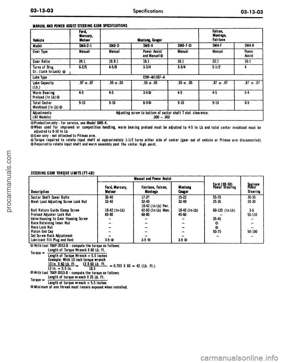
MANUAL AND POWER
Vehicle
Model
Gear Type
Gear Ratio
Turns of
Strg.
Gr. (Lock to Lock)
®
Lube Type
Lube Capacity
(Lb.)
Worm Bearing
Preload (In Lb)®
Total Center
Meshload(lnLb)®
Adjustments
(All Models)
ASSIST STEERING GEAR SPECIFICATIONS
Ford,
Mercury,
Meteor
SM/VD-1
Manual
24:1
6-2/5
.97
±
.07
4-5
9-10
SMB-D
Manual
19.9:1
4-5/8
.55
±
.05
4-5
9-10
Adjusting
Mustang, Cougar
SMBK
Power Assist
and Manual®
16:1
3-3/4
ESW-M1C87-A
.55
±
.05
3-4®
8-9®
screw to bottom
of
sector
.000 -.002
SMB-F®
Manual
16:1
3-3/4
.55
±
.05
4-5
9-10
shaft T slot clearance:
Falcon,
Mont ego,
Fairlane
SMA-F
Manual
22:1
5-1/2
.87
±
.07
4-5
9-10
SMA-B
Power
Assist
16:1
4
.87
±
.07
3-4
8-9
©Production only
-
for service, use Model SMB-K.
®When used
for
improved
or
competition handling, worm bearing preload must
be
adjusted
to
4-5
In
Lb and total center meshload must
be
adjusted to 9-10 In Lb.
®Gear only
-
not attached to Pitman arm.
0Torque required
to
rotate input shaft
at
approximately 1-1/2 turns either side
of
center (gear
out of
vehicle
or
Pitman arm disconnected).
©Requiredto rotate input shaft and worm assembly past
the
center high point.
STEERING GEAR TORQUE UMITS(FT-LB)
Description
Sector Shaft Cover Bolts
Mesh Load Adjusting Screw Lock Nut
Ball Return Guide Clamp Screw
Preload Adjuster Lock Nut
Valve Housing
to
Gear Housing Screw
Race Retaining Inner Nut
Race Lock Nut
Piston End Cap
Set Screw-Rack Adjustment
Lubricant Fill Plug and Vent
Manual and Power Assist
Ford,
Mercury,
Meteor
30-40
32-40
18-42 (In-Lb)
60-80
3-9®
Fairlane, Falcon,
Montego
17-2?
32-40
18-42 (In-Lb) Pwr.
42-60 (In-Lb) Man.
60-80
3-9®
Mustang
Cougar
15-22
32-40
18-42 (In-Lb)
45-60
3-9®
Power steering
55-70
25-35
60-120 (In-Lb)
35-45
(D
®
50-75
Steering
30-35
20-30
3-6
50-110
50-100
® With tool T66P-3553-B
•
compute the torque as follows:
Length
of
Torque Wrench
X
60 Lb.
Ft.
°rque
"
Length
of
Torque Wrench
+
5.5 Inches
Example: With 13 inch torque wrench
13ln.
X
60 Lb. Ft. 13
X
60 Lb.
Ft.
13
In.
+
5.5 In.
18.5
®With tool T66P-3553-B
•
compute the torque as follows:
Length
of
torque wrench
X
25 Lb.
Ft.
Length of torque wrench
+
5.5 Inches
©Minimum
of
one thread must remain exposed when installed.
-0.703 X60- 42 (Lb.
Ft.)procarmanuals.com
Page 183 of 413

03-13-04
Specifications
03-13-04
STEERING LINKAGE TORQUE LIMITS (FT-LBS)
Description
Cylinder Mounting Bracket
to
(Side Hole)
Underbodyor Frame (Bottom Hole)
Power Cylinder
to
Bracket
Power Cylinder
to
Bracket Lock
Nut
Steering
Tie Rod End to
Spindle
Arm
Idler
Arm
Mounting Bracket
to
Underbody
or
Frame
Pitman Arm
to
Control Valve (Power Steering)
Steering Gear
to
Side Rail
or
Frame
Pitman
Arm to
Sector Shaft
Idler
Arm to
Pitman Arm-to-ldler
Arm Rod
Spindle Connecting
Rod
Clamp
to
Adjusting
Sleeve
Pitman
Arm to
Steering Arm-to-ldler
Arm Rod
Steering Spindle
Arm
Connecting
Rod to
Arm-to-ldler
Arm Rod
Cougar, Fairlane,
Falcon,
Mont
ego,
Mustang
28-35
35-43
18-24
3-5
30-40
©
28-35
35-47
©
50-65
150-225
60-80®
10-14
35-47
©
30-40
©
Ford,
Mercury,
Meteor
-
-
-
-
35-47®
28-35
-
50-65
150-225
60-80
®
8-13
35-47
©
35-47
®
Continental
Mark
III
Thunder bird
-
-
-
-
35-47
©
28-35
-
50-65
150-225
60-80
©
8-13
35-47
©
35-47
©
Lincoln
Continental
-
-
-
-
40-55
20-30
-
50-65
150-200
40-55
19-26
40-55
40-55
CD
Torque
to low
limit
of
specification;
then,
tighten
the nut to the
nearest cotter
pin
slot
and
insert
the
cotter
pin.
STEERING COLUMN TORQUE LIMITS (FT-LBS)
Description
Column Lower Bracket
to
Column Upper Bracket
Intermediate Bracket
to
Brake Pedal
Support Bracket
Lower Trim Shroud
to
Upper Trim Shroud
Flex Coupling
to
Steering Gear
Flex Coupling
to
Steering Shaft Flange
Flex Coupling
to
Steering Shaft
Tee Plate
to
Instrument Panel
Steering Wheel Attaching
Nut
Brake Pedal Support Bracket
to
Brake
Pedal Support
Column Upper Bracket
to
Instrument Panel
Column Upper Bracket
to
Lower Clamp
Ford,
Mercury,
Meteor
Upper
9-20
Lower
8-12
9-20
5-10
24-37
10-18
-
8-13
30-40
_
-
-
Fairlane,
Falcon,
Mont
ego
10-20
_
-
24-37
12-18
-
3-8
30-40
28-42
10-16
-
Cougar,
Mustang
8-15
_
-
24-37
10-18
-
5-15
30-40
13-25
-
-
Lincoln
Continental
_
_
-
25-35
-
25-35
4-9
20-30
_
10-15
8-12
Continental
Mark
III
Thunder bird
_
_
-
25-35
-
25-35
4-9
30-40
28-42
7-12
7-1?procarmanuals.com
Page 184 of 413

03-13-05
Specifications
03-13-05
TORQUE LIMITS-FRONT SUSPENSION
MONTEGO, FALCON,
FAIR
LANE,
MUSTANG AND COUGAR
Description
Shock Absorber Upper Attachment
Shock Absorber Upper Bracket to Body
Front Suspension Compression Bumper to Body
Brake Backing Plate to Spindle
Upper Arm and Inner Shaft to Body
Spring Seat to Upper Arm
Shock Absorber to Spring Seat
Ball Joint to Spindle (Upper and Lower)
Wheel Bearing Adjusting Nut
Strut to Lower Arm
Lower Arm to Underbody
Stabilizer Bar Mounting Bracket to Underbody
Strut to Underbody
Stabilizer Bar to Lower Arm
Caliper to Spindle (Disc Brake) • Upper
- Lower
Strut to Underbody Slotted Nut
Ft • Lbs
Montego, Falcon, Fairlane
20-28
15-25
12-17
9-14 (Disc) 25-45 (Drum)
75-100
30-40
8-12
60-90 ©
17-25 ©
75-105
75-100
17-25
60-80
5-10
110-140
55-75
Mustang and Cougar
10-15
22-34
12-17
9-14 (Disc) 28-45 (Drum)
75-100
25-40
8-12
60-90 ©
17-25 ©
70-105
75-100
17-25
60-80
8-12
110-120
55-75
50-70 | 50-70
©Torquethe adjusting nut to 17-25 ft-lb. Locate nut lock on adjusting nut so ,ctstellations are aligned with cotter pin hole in spindle. Then,
backoff adjusting nut and nut lock so the next castellation aligns with the cotter pin hole.
TORQE LIMITS-fRONT SUSPENSION
FORD,
MERCURY, METEOR
Description
Lower Arm to No. 2 Crossmember
Upper Arm to Frame
Upper Arm Bumper
Brake Backing Plate and Cylinder Assembly
to Spindle
Stabilizer Bar to Lower Arm
Ball Joint to Spindle (Upper and Lower)
Ft Lbs
55-75
100-130
15-25
80-106
5-10
60-90®
Description
Brake Backing Plate to Spindle
Strut to Lower Arm
Stabilizer Bar to Frame
Strut to Frame
Shock Absorber Upper Attachment
Shock Absorber Lower Arm
Caliper to Spindle (Disc Brake)
Ft-Lbs
25-45
70-113
18-27
60-90 ©
20-28
8 12
120-130
©Torque to specification, then tighten the nut to the nearest cotter pin slot and insert the cotter pin.
TORQUE LIMITS-FRONT SUSPENSION
THUNDERBIRD, CONTINENTAL MARK
Description
Lower Arm to #2 Crossmember
Upper Arm to Frame
Upper Arm Bumper
Stabilizer Bar to Lower Arm
Ball Joint to Spindle (Upper and Lower)
Strut to Lower Arm
Stabilizer Bar to Mounting Bracket
Strut to Frame
Shock Absorber Upper Attachment
Shock Absorber to Lower Arm
Brake Splash Shield (Disc) to Spindle
Caliper to Spindle (Disc Brake)
Upper Bolt
Lower Bolt
Torque
Ft-Lbs
60-90
100-150
15-25
5-10
©60-90
70-113
8-12
©60-90
20-23
8-12
9-14
110-140
90-120
©Torque to minimum specification;
then,
tighten the nut to the nearest cotter pin slot and insert the cotter pin.procarmanuals.com