Page 137 of 413

03-06-03
Manual Steering
03-06-03
MAJOR REPAIR OPERATIONS
STEERING GEAR
DISASSEMBLY
1. Rotate the steering shaft 3 turns
from either stop.
2.
After removing the sector adjust-
ing screw locknut and the housing
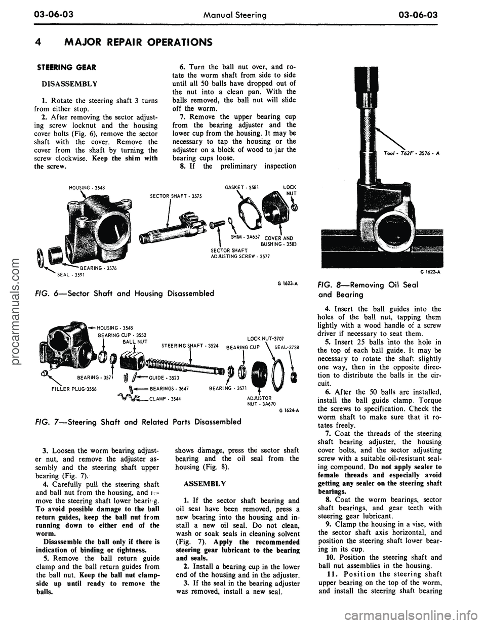
cover bolts (Fig. 6), remove the sector
shaft with the cover. Remove the
cover from the shaft by turning the
screw clockwise. Keep the shim with
the screw.
HOUSING
•
3548
6. Turn the ball nut over, and ro-
tate the worm shaft from side to side
until all 50 balls have dropped out of
the nut into a clean pan. With the
balls removed, the ball nut will slide
off the worm.
7. Remove the upper bearing cup
from the bearing adjuster and the
lower cup from the housing. It may be
necessary to tap the housing or the
adjuster on a block of wood to jar the
bearing cups loose.
8. If the preliminary inspection
GASKET
• 3581
SHIM-3A657 COVER
AND
BUSHING
•
3583
SECTOR SHAFT
ADJUSTING SCREW
.
3577
•BEARING-3576
SEAL
- 3591
G 1623-A
FIG. 6—Sector Shaft
and
Housing Disassembled
-^-HOUSING-3548
BEARING
CUP •
3552
BALL
NUT
BEARING-3571
FILLER PLUG-3556
LOCK NUT-3707
3524 BEARING
CUP \
SEAL-3738
•GUIDE -3523
• BEARINGS
•
3647
.CLAMP-3544
BEARING
• 3571
G 1624-A
FIG. 7—Steering Shaft
and
Related Parts Disassembled
3.
Loosen the worm bearing adjust-
er nut, and remove the adjuster as-
sembly and the steering shaft upper
bearing (Fig. 7).
4.
Carefully pull the steering shaft
and ball nut from the housing, and i •-
move the steering shaft lower bearr g.
To avoid possible damage to the ball
return guides, keep
the
ball
nut
from
running down
to
either
end of the
worm.
Disassemble
the
ball only
if
there
is
indication
of
binding
or
tightness.
5.
Remove the ball return guide
clamp and the ball return guides from
the ball
nut.
Keep
the
ball
nut
clamp-
side up until ready to remove the
balls.
shows damage, press the sector shaft
bearing and the oil seal from the
housing (Fig. 8).
ASSEMBLY
1. If the sector shaft bearing and
oil seal have been removed, press a
new bearing into the housing and in-
stall a new oil seal. Do not clean,
wash or soak seals in cleaning solvent
(Fig.
7).
Apply
the
recommended
steering gear lubricant
to the
bearing
and seals.
2.
Install a bearing cup in the lower
end of the housing and in the adjuster.
3.
If the seal in the bearing adjuster
was removed, install a new seal.
Tool
-
T62F
•
3576
- A
G 1622-A
FIG.
8—Removing
Oil
Seal
and Bearing
4.
Insert the ball guides into the
holes of the ball nut, tapping them
lightly with a wood handle of a screw
driver if necessary to seat them.
5.
Insert 25 balls into the hole in
the top of each ball guide. It may be
necessary to rotate the shafi: slightly
one way, then in the opposite direc-
tion to distribute the balls in the cir-
cuit.
6. After the 50 balls are installed,
install the ball guide clamp. Torque
the screws to specification. Check the
worm shaft to make sure that it ro-
tates freely.
7. Coat the threads of the steering
shaft bearing adjuster, the housing
cover bolts, and the sector adjusting
screw with a suitable oil-resisi:ant seal-
ing compound. Do not apply sealer to
female threads and especially avoid
getting any sealer on the steering shaft
bearings.
8.
Coat the worm bearings, sector
shaft bearings, and gear teeth with
steering gear lubricant.
9. Clamp the housing in a vise, with
the sector shaft axis horizontal, and
position the steering shaft lower bear-
ing in its cup.
10.
Position the steering shaft and
ball nut assemblies in the housing.
11.
Position the steering shaft
upper bearing on the top of the worm,
and install the steering shaft bearingprocarmanuals.com
Page 138 of 413

03-06-04
Manual Steering
03-06-04
adjuster and the adjuster nut and
bearing cup. Leave the nut loose.
12.
Adjust the worm bearing pre-
load, using an in-lb torque wrench
(Fig. 9). See Part 3-13 for the speci-
fied preload.
13.
Position the sector adjusting
screw and adjuster shim, and check
the end clearance which should not
exceed 0.002 inch between the screw
head and the end of the sector shaft.
If clearance is greater than 0.002 inch,
add enough shims to reduce the end
play to within the 0.002 inch toler-
ance.
14.
Start the sector shaft adjusting
screw into the housing cover.
15.
Install a new gasket on the
housing cover.
16.
Rotate the steering shaft until
the ball nut teeth are in position to
mesh with the sector gear, tilting the
In - /b Torque Wrench
ADJUSTER NUT
21-A
FIG. 9—Checking Steering Shaft
Bearing Preload
housing so that the ball will tip
toward the housing cover opening.
17.
Lubricate the sector shaft jour-
nal and install the sector shaft and
cover.
18.
With the housing cover turned
out of the way fill the gear with 0.97
lbs of gear lubricant. Push the
housing cover and sector shaft assem-
blies into place, and install the two
top housing cover bolts. Do not tight-
en the cover bolts until it is certain
that there is some lash between ball
nut and sector gear teeth. Hold or
push the cover away from the ball nut,
then torque the bolts to specification.
19.
After loosely installing the sec-
tor shaft adjusting screw lock nut, ad-
just the sector shaft mesh load. See
Part 3-13 for the specified mesh load;
then, tighten the adjusting screw lock
nut.procarmanuals.com
Page 139 of 413

03-07-01
Ford Design Non-Integral Power Steering System
03-07-01
PART
3-7
Ford Design Non-Integral Power
Steering System
COMPONENT INDEX
CONTROL VALVE
Disassembly
and
Overhaul
Removal
and
Installation
CONTROL VALVE CENTERING SPRING
Adjustment
CONTROL VALVE
TO
POWER STEERING
CYLINDER HOSE
Removal
and
Installation
HOISTING INSTRUCTIONS
POWER CYLINDER
Removal
and
Installation
POWER CYLINDER SEAL
Removal
and
Installation
POWER STEERING PUMP CLEANING
AND INSPECTION
(See
Part 03-01)
Removal
and
Installation
POWER STEERING PUMP
TO
CONTROL
VALVE HOSE
Removal
and
Installation
STEERING GEAR
Cleaning
and
Inspection
(See Part 03-01)
MODEL APPLICATION
All
Models
Ford
N/A
N/A
N/A
N/A
N/A
N/A
N/A
N/A
N/A
Mercury
N/A
N/A
N/A
N/A
N/A
N/A
N/A
N/A
N/A
Meteor
N/A
N/A
N/A
N/A
N/A
N/A
N/A
N/A
N/A
Cougar
N/A
N/A
N/A
N/A
N/A
N/A
N/A
N/A
N/A
Fairlane
07-04
07-03
07-02
07-02
07-02
07-04
07-06
07-03
07-02
Falcon
07-04
07-03
07-02
07-02
07-02
07-04
07-06
07-03
07-02
Montego
07-04
07-03
07-02
07-02
07-02
07-04
07-06
07-03
07-02
Mustang
07-04
07-03
07-02
07-02
07-02
07-04
07-06
07-03
07-02
Lincoln-
Continental
07-04
07-03
07-02
07-02
07-02
07-04
07-06
07-03
07-02
Thunderbird
N/A
N/A
N/A
N/A
N/A
N/A
N/A
N/A
N/A
Continental-
Mark
III
N/A
N/A
N/A
N/A
N/A
N/A
N/A
N/A
N/A
A page number indicates that
the
item
is for the
vehicle listed
at the
head
of the
column.
N/A indicates that
the
item
is not
applicable
to the
vehicle listed.
DESCRIPTION
The Ford Non-Integral Power
Steering System
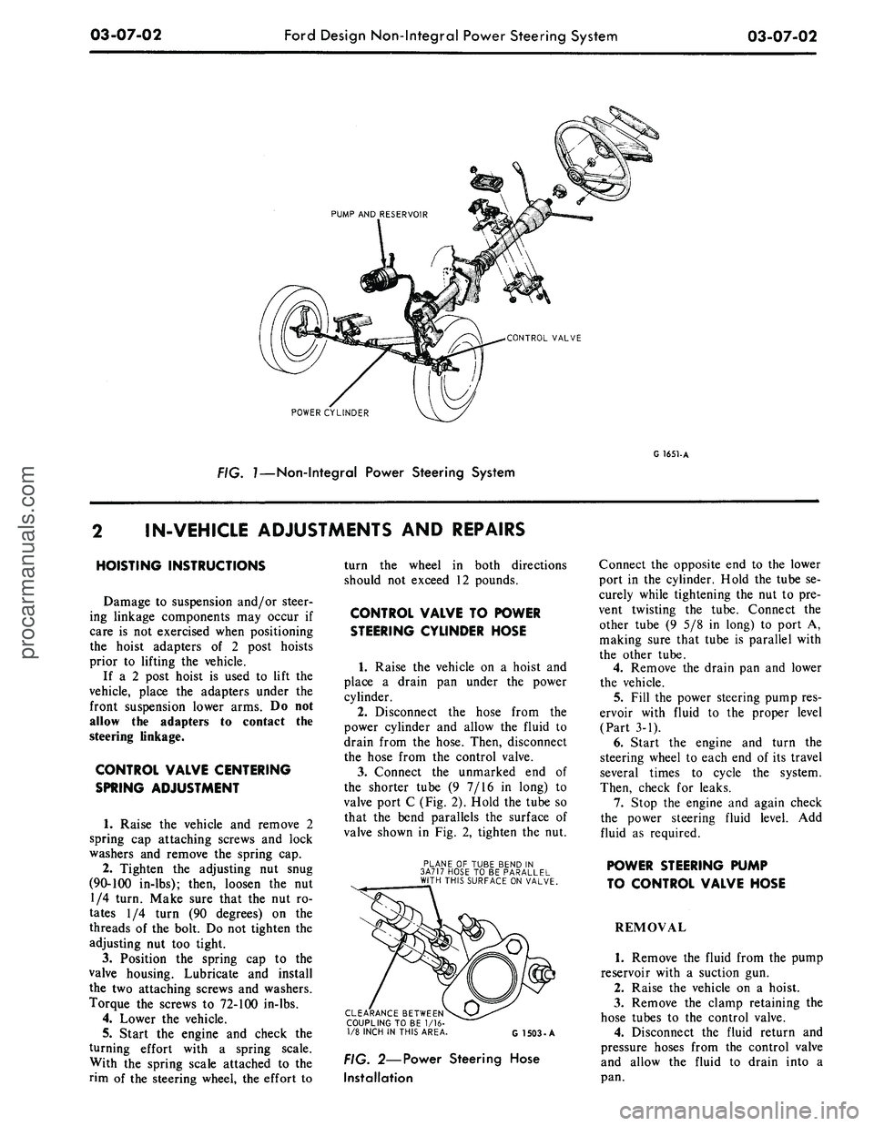
(Fig. 1) is a
hydrauli-
cally controlled linkage-type steering
system which includes
an
integral
pump
and
fluid reservoir,
a
control
valve,
a
power cylinder,
the
connecting
fluid lines,
and the
steering linkage.
The hydraulic pump
and
belt, driven
from
the
engine crankshaft, draws
fluid from
the
reservoir
and
provides
fluid pressure
for the
system. Within
the pump itself
is a
pressure-relief
valve which governs
the
pressures
within
the
steering system according
to
the
varying conditions
of
operation.
After fluid
has
passed from
the
pump
to
the
control valve
and the
power
cyl-
inder,
it
returns
to the
reservoir.
procarmanuals.com
Page 140 of 413

03-07-02
Ford Design Non-Integral Power Steering System
03-07-02
PUMP AND RESERVOIR
CONTROL VALVE
POWER CYLINDER
FIG. 7—Non-Integral Power Steering System
G 1651-A
IN-VEHICLE ADJUSTMENTS
AND
REPAIRS
HOISTING INSTRUCTIONS
Damage
to
suspension and/or steer-
ing linkage components
may
occur
if
care
is not
exercised when positioning
the hoist adapters
of 2
post hoists
prior
to
lifting
the
vehicle.
If
a 2
post hoist
is
used
to
lift
the
vehicle, place
the
adapters under
the
front suspension lower arms.
Do not
allow
the
adapters
to
contact
the
steering linkage.
CONTROL VALVE CENTERING
SPRING ADJUSTMENT
1.
Raise
the
vehicle
and
remove
2
spring
cap
attaching screws
and
lock
washers
and
remove
the
spring
cap.
2.
Tighten
the
adjusting
nut
snug
(90-100 in-lbs); then, loosen
the nut
1/4 turn. Make sure that
the nut ro-
tates
1/4
turn
(90
degrees)
on the
threads
of the
bolt.
Do not
tighten
the
adjusting
nut too
tight.
3.
Position
the
spring
cap to the
valve housing. Lubricate
and
install
the
two
attaching screws
and
washers.
Torque
the
screws
to
72-100 in-lbs.
4.
Lower
the
vehicle.
5.
Start
the
engine
and
check
the
turning effort with
a
spring scale.
With
the
spring scale attached
to the
rim
of the
steering wheel,
the
effort
to
turn
the
wheel
in
both directions
should
not
exceed
12
pounds.
CONTROL VALVE
TO
POWER
STEERING CYLINDER HOSE
1.
Raise
the
vehicle
on a
hoist
and
place
a
drain
pan
under
the
power
cylinder.
2.
Disconnect
the
hose from
the
power cylinder
and
allow
the
fluid
to
drain from
the
hose. Then, disconnect
the hose from
the
control valve.
3.
Connect
the
unmarked
end of
the shorter tube
(9 7/16 in
long)
to
valve port
C
(Fig. 2). Hold
the
tube
so
that
the
bend parallels
the
surface
of
valve shown
in Fig. 2,
tighten
the nut.
PLANE
OF
TUBE BEND
IN
3A717 HOSE
TO BE
PARALLEL
WITH THIS SURFACE ON VALVE.
CLEARANCE BETWEEN
COUPLING TO
BE 1/16-
1/8 INCH
IN
THIS AREA
G 1503-A
FIG. 2—Power Steering Hose
Installation
Connect
the
opposite
end to the
lower
port
in the
cylinder. Hold
the
tube
se-
curely while tightening
the nut to pre-
vent twisting
the
tube. Connect
the
other tube
(9 5/8 in
long)
to
port
A,
making sure that tube
is
parallel with
the other tube.
4.
Remove
the
drain
pan and
lower
the vehicle.
5.
Fill
the
power steering pump res-
ervoir with fluid
to the
proper level
(Part
3-1).
6. Start
the
engine
and
turn
the
steering wheel
to
each
end of its
travel
several times
to
cycle
the
system.
Then, check
for
leaks.
7.
Stop
the
engine
and
again check
the power steering fluid level.
Add
fluid
as
required.
POWER STEERING PUMP
TO CONTROL VALVE HOSE
REMOVAL
1.
Remove
the
fluid from
the
pump
reservoir with
a
suction
gun.
2.
Raise
the
vehicle
on a
hoist.
3.
Remove
the
clamp retaining
the
hose tubes
to the
control valve.
4.
Disconnect
the
fluid return
and
pressure hoses from
the
control valve
and allow
the
fluid
to
drain into
a
pan.procarmanuals.com
Page 141 of 413

03-07-03
Ford Design Non-Integral Power Steering System
03-07-03
5.
Lower the vehicle and disconnect
the fluid return hose from the reser-
voir.
6. Disconnect the fluid pressure
hose from the pump outlet fitting.
7.
Remove 1 bolt attaching the
hoses,
insulator, and the retainer to
the frame side rail and remove the
hoses,
and the insulator and retainer
as an assembly from the vehicle.
8. Remove the pressure and return
hoses from the retainer and insulator.
INSTALLATION
1.
Install the pressure and return
hoses in the insulator and retainer.
Paint stripe on pressure hose must be
aligned with slot in insulator. Paint or
tape band on return hose must be cen-
tered in insulator. Position the assem-
bly to the frame side rail and install
the attaching bolt.
2.
Place a hose clamp on the fluid
return hose and install the hose on the
power steering pump reservoir return
fitting.
3.
Torque the pump outlet fitting to
specification (Part 3-13). Then, con-
nect the pressure hose to the outlet fit-
ting and torque the fitting to specifica-
tion.
4.
Raise the vehicle and connect the
pressure and return lines to the con-
trol valve.
5.
Install the clamp to retain the
hose tubes to the control valve.
6. Lower the vehicle and fill the
power steering pump reservoir with
fluid, C1AZ-19582-A, to the proper
level (Part 3-1).
7.
Start the engine and turn the
steering wheel to each end of its travel
several times to cycle the system.
Then, check for fluid leaks.
8. Stop the engine and again check
the power steering fluid level (Part
3-1). Add fluid as required.
REMOVAL AND INSTALLATION
HOISTING INSTRUCTIONS
Damage to suspension and/or steer-
ing linkage components may occur if
care is not exercised when positioning
the hoist adapters of 2 post hoists
prior to lifting the vehicle.
If a 2 post hoist is used to lift the
vehicle, place the adapters under the
front suspension lower arms. Do not
allow the adapters to contact the
steering linkage.
STEERING GEAR
Refer to Group 3-6, Section 3 for
detailed instructions.
POWER STEERING PUMP
Refer to Group 3-10, Section 3 for
detailed instructions.
POWER STEERING CONTROL
VALVE
REMOVAL
1.
Disconnect the 4 fluid line fit-
tings at the control valve, and drain
the fluid from the lines. Turn the front
wheels to the left and right several
times to force all the fluid from the
system.
2.
Loosen the clamping nut and
bolt at the right end of the sleeve.
3.
Remove the roll pin from the
steering arm-to-idler arm rod -through
the slot in the sleeve.
4.
Remove the control valve ball
stud nut.
5.
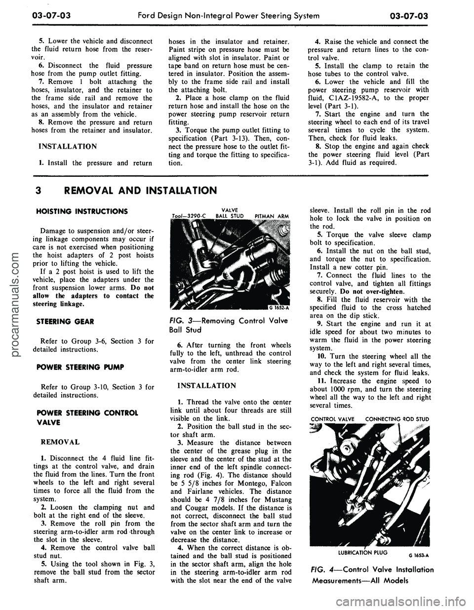
Using the tool shown in Fig. 3,
remove the ball stud from the sector
shaft arm.
VALVE
Too/-3290-C BALL STUD PITMAN ARM
FIG. 3—Removing Control Valve
Ball Stud
6. After turning the front wheels
fully to the left, unthread the control
valve from the center link steering
arm-to-idler arm rod.
INSTALLATION
1.
Thread the valve onto the center
link until about four threads are still
visible on the link.
2.
Position the ball stud in the sec-
tor shaft arm.
3.
Measure the distance between
the center of the grease plug in the
sleeve and the center of the stud at the
inner end of the left spindle connect-
ing rod (Fig. 4). The distance should
be 5 5/8 inches for Montego, Falcon
and Fairlane vehicles. The distance
should be 4 7/8 inches for Mustang
and Cougar models. If the distance is
not correct, disconnect the ball stud
from the sector shaft arm and turn the
valve on the center link to increase or
decrease the distance.
4.
When the correct distance is ob-
tained and the ball stud is positioned
in the sector shaft arm, align the hole
in the steering arm-to-idler arm rod
with the slot near the end of the valve
sleeve. Install the roll pin in the rod
hole to lock the valve in position on
the rod.
5.
Torque the valve sleeve clamp
bolt to specification.
6. Install the nut on the ball stud,
and torque the nut to specification.
Install a new cotter pin.
7.
Connect the fluid lines to the
control valve, and tighten all fittings
securely. Do not over-tighten.
8. Fill the fluid reservoir with the
specified fluid to the cross hatched
area on the dip stick.
9. Start the engine and run it at
idle speed for about two minutes to
warm the fluid in the power steering
system.
10.
Turn the steering wheel all the
way to the left and right several times,
and check the system for fluid leaks.
11.
Increase the engine speed to
about 1000 rpm, and turn the steering
wheel all the way to the left and right
several times.
CONTROL VALVE CONNECTING ROD STUD
LUBRICATION PLUG
G1653-A
FIG. 4—Control Valve Installation
Measurements—All Modelsprocarmanuals.com
Page 142 of 413

03-07-04
Ford Design Non-Integral Power Steering System
03-07-04
12.
Stop the engine, and check the
control valve and hose connections for
fluid leaks. Correct the cause of any
leaks.
13.
Check the fluid level, and refill
the reservoir if necessary.
14.
With the engine running check
the position of the steering wheel
when the front wheels are in the
straight-ahead position.Do not make
any adjustments until toe-in is
checked.
15.
Keep the engine running, and
check toe-in. If either toe-in or steer-
ing wheel position is not correct make
all necessary adjustments (Part 3-1) at
the spindle connecting rod sleeves.
16.
Check the effort to turn the
wheels in both directions. The effort
should be about equal in both direc-
tions.
POWER CYLINDER
REMOVAL
1.
Disconnect the two fluid lines
from the power cylinder and allow
them to drain into a container.
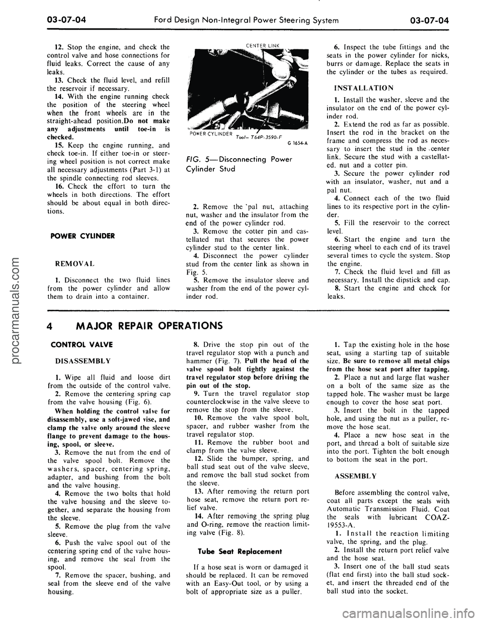
CENTER LINK
POWER CYLINDER
Tool- T64P-3590-F
G 1654-A
FIG. 5—Disconnecting Power
Cylinder Stud
2.
Remove the 'pal nut, attaching
nut, washer and the insulator from the
end of the power cylinder rod.
3.
Remove the cotter pin and cas-
tellated nut that secures the power
cylinder stud to the center link.
4.
Disconnect the power cylinder
stud from the center link as shown in
Fig. 5.
5.
Remove the insulator sleeve and
washer from the end of the power cyl-
inder rod.
6. Inspect the tube fittings and the
seats in the power cylinder for nicks,
burrs or damage. Replace the seats in
the cylinder or the tubes as required.
INSTALLATION
1.
Install the washer, sleeve and the
insulator on the end of the power cyl-
inder rod.
2.
Extend the rod as far as possible.
Insert the rod in the bracket on the
frame and compress the rod as neces-
sary to insert the stud in the -center
link. Secure the stud with a castellat-
ed, nut and a cotter pin.
3.
Secure the power cylinder rod
with an insulator, washer, nut and a
pal nut.
4.
Connect each of the two fluid
lines to its respective port in the cylin-
der.
5.
Fill the reservoir to the correct
level.
6. Start the engine and turn the
steering wheel to each end of its travel
several times to cycle the system. Stop
the engine.
7.
Check the fluid level and fill as
necessary. Install the dipstick and cap.
8. Start the engine and check for
leaks.
MAJOR REPAIR OPERATIONS
CONTROL VALVE
DISASSEMBLY
1.
Wipe all fluid and loose dirt
from the outside of the control valve.
2.
Remove the centering spring cap
from the valve housing (Fig. 6).
When holding the control valve for
disassembly, use a soft-jawed vise, and
clamp the valve only around the sleeve
flange to prevent damage to the hous-
ing, spool, or sleeve.
3.
Remove the nut from the end of
the valve spool bolt. Remove the
washers, spacer, centering spring,
adapter, and bushing from the bolt
and the valve housing.
4.
Remove the two bolts that hold
the valve housing and the sleeve to-
gether, and separate the housing from
the sleeve.
5.
Remove the plug from the valve
sleeve.
6. Push the valve spool out of the
centering spring end of the valve hous-
ing, and remove the seal from the
spool.
7.
Remove the spacer, bushing, and
seal from the sleeve end of the valve
housing.
8. Drive the stop pin out of the
travel regulator stop with a punch and
hammer (Fig. 7). Pull the head of the
valve spool bolt tightly against the
travel regulator stop before driving the
pin out of the stop.
9. Turn the travel regulator stop
counterclockwise in the valve sleeve to
remove the stop from the sleeve.
10.
Remove the valve spool bolt,
spacer, and rubber washer from the
travel regulator stop.
11.
Remove the rubber boot and
clamp from the valve sleeve.
12.
Slide the bumper, spring, and
ball stud seat out of the valve sleeve,
and remove the ball stud socket from
the sleeve.
13.
After removing the return port
hose seat, remove the return port re-
lief valve.
14.
After removing the spring plug
and O-ring, remove the reaction limit-
ing valve (Fig. 8).
Tube Seat Replacement
If a hose seat is worn or damaged it
should be replaced. It can be removed
with an Easy-Out tool, or by using a
bolt of appropriate size as a puller.
1.
Tap the existing hole in the hose
seat, using a starting tap of suitable
size.
Be sure to remove all metal chips
from the hose seat port after tapping.
2.
Place a nut and large flat washer
on a bolt of the same size as the
tapped hole. The washer must be large
enough to cover the hose seat port.
3.
Insert the bolt in the tapped
hole,
and using the nut as a puller, re-
move the hose seat.
4.
Place a new hose seat in the
port, and thread a bolt of suitable size
into the port. Tighten the bolt enough
to bottom the seat in the port.
ASSEMBLY
Before assembling the control valve,
coat all parts except the seals with
Automatic Transmission Fluid. Coat
the seals with lubricant COAZ-
19553-A.
1.
Install the reaction limiting
valve, the spring, and the plug.
2.
Install the return port relief valve
and the hose seat.
3.
Insert one of the ball stud seats
(flat end first) into the ball stud sock-
et, and insert the threaded end of the
ball stud into the socket.procarmanuals.com
Page 143 of 413

03-07-05
Ford Design Non-Integral Power Steering System
03-07-05
•
SPRING
SEAT
REACTION
SPRING
\
REACTION
\
VALVE
VALVE
HOUSING
SPRING PLUG
AND O-RING SPACER
WASHERX
CUSHION
STOP
PIN
TRAVEL
REGULATOR
CLAMP
FIG. 6—Control Valve Disassembled—Typical
4.
Place
the
socket
in the
control
valve sleeve
so
that
the
threaded
end
of
the
ball stud
can be
pulled
out
through
the
slot
in the
sleeve (Fig.
9).
5.
Place
the
other ball stud seat,
and spring,
and the
bumper (Fig.
6) in
the socket,
and
install
and
securely
tighten
the
travel regulator stop.
6. Loosen
the
stop just enough
to
align
the
nearest hole
in the
stop with
the slot
in the
ball stud socket,
and in-
stall
the
stop
pin in the
ball stud sock-
VAIVE
SPOOL
BOLT
BALL
STUD
SOCKET
TRAVEL
REGULATOR
STOP
G
1656-A
FIG. 7—Removing Stop
Pin
et, travel regulator stop,
and
valve
spool bolt
(Fig. 7).
7.
Install
the
rubber boot, clamp,
and
the
plug
on the
control valve
sleeve. Make sure that
the
lubrication
fitting
is
turned
on
tightly
and
does
not bind
on the
ball stud socket.
8. Insert
the
valve spool
in the
valve
housing. Rotate
the
spool while insert-
ing
it in the
housing
(Fig. 10).
9. Move
the
spool toward
the cen-
tering spring
end of the
housing,
and
place
the
small seal bushing,
and spa-
cer
in the
sleeve
end of the
housing.
10.
Press
the
valve spool against
the inner
lip of the
seal
and, at the
same time, guide
the lip of the
seal
over
the
spool with
a
small screwdriv-
G
1657-A
FIG. 8—Removing Reaction Valve
Plug
er.
Do not
nick
or
scratch
the
seal
or
the spool during installation.
11.
Place
the
sleeve
end of the
housing
on a
flat surface
so
that
the
seal, bushing,
and
spacer
are at the
bottom
end and
push down
the
valve
spool until
it
stops.
12.
Carefully install
the
spool seal
and bushing
in the
centering spring
end
of the
housing. Press
the
seal
against
the end of the
spool., guiding
the seal over
the
spool with
a
small
screwdriver.
Do not
nick
or
scratch
the seal
or the
spool during installa-
tion.
CONTROL
VALVE
SLEEVE
BALL
STUD
SEAT-
BALL
STUD'
BALL
STUD
SOCKET'
G
16
58-A
FIG. 9—Installing Ball Socket,
Seal
and
Bracketprocarmanuals.com
Page 144 of 413

03-07-06
Ford Design Non-Integral Power Steering System
03-07-06
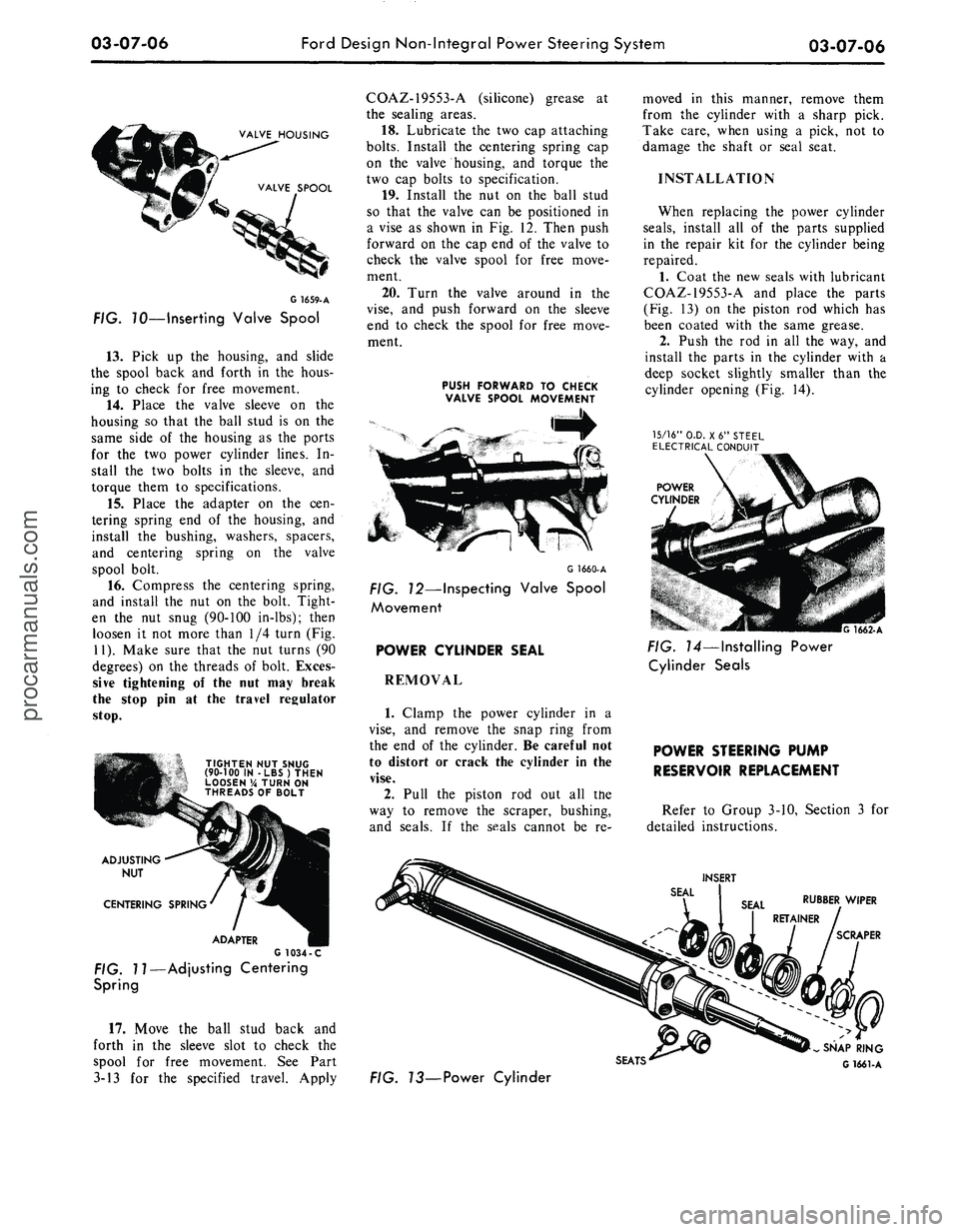
VALVE HOUSING
VALVE SPOOL
G
1659-
A
FIG. 70—Inserting Valve Spool
13.
Pick up the housing, and slide
the spool back and forth in the hous-
ing to check for free movement.
14.
Place the valve sleeve on the
housing so that the ball stud is on the
same side of the housing as the ports
for the two power cylinder lines. In-
stall the two bolts in the sleeve, and
torque them to specifications.
15.
Place the adapter on the cen-
tering spring end of the housing, and
install the bushing, washers, spacers,
and centering spring on the valve
spool bolt.
16.
Compress the centering spring,
and install the nut on the bolt. Tight-
en the nut snug (90-100 in-lbs); then
loosen it not more than 1/4 turn (Fig.
11).
Make sure that the nut turns (90
degrees) on the threads of bolt. Exces-
sive tightening of the nut may break
the stop pin at the travel regulator
stop.
TIGHTEN NUT SNUG
(90-100 IN -LBS) THEN
LOOSEN % TURN ON
THREADS OF BOLT
ADJUSTING
NUT
CENTERING SPRING
ADAPTER
G 1034 -C
FIG. 11—Adjusting Centering
Spring
17.
Move the ball stud back and
forth in the sleeve slot to check the
spool for free movement. See Part
3-13 for the specified travel. Apply
COAZ-19553-A (silicone) grease at
the sealing areas.
18.
Lubricate the two cap attaching
bolts.
Install the centering spring cap
on the valve housing, and torque the
two cap bolts to specification.
19.
Install the nut on the ball stud
so that the valve can be positioned in
a vise as shown in Fig. 12. Then push
forward on the cap end of the valve to
check the valve spool for free move-
ment.
20.
Turn the valve around in the
vise,
and push forward on the sleeve
end to check the spool for free move-
ment.
PUSH FORWARD TO CHECK
VALVE SPOOL MOVEMENT
G 1660-A
FIG. 12—Inspecting Valve Spool
Movement
POWER CYLINDER SEAL
REMOVAL
1.
Clamp the power cylinder in a
vise,
and remove the snap ring from
the end of the cylinder. Be careful not
to distort or crack the cylinder in the
vise.
2.
Pull the piston rod out all the
way to remove the scraper, bushing,
and seals. If the seals cannot be re-
moved in this manner, remove them
from the cylinder with a sharp pick.
Take care, when using a pick, not to
damage the shaft or seal seat.
INSTALLATION
When replacing the power cylinder
seals,
install all of the parts supplied
in the repair kit for the cylinder being
repaired.
1.
Coat the new seals with lubricant
COAZ-19553-A and place the parts
(Fig. 13) on the piston rod which has
been coated with the same grease.
2.
Push the rod in all the way, and
install the parts in the cylinder with a
deep socket slightly smaller than the
cylinder opening (Fig. 14).
15/16"
O.D. X6" STEEL
ELECTRICAL CONDUIT
POWER
CYLINDER
G 1662-A
FIG. 14—Installing Power
Cylinder Seals
POWER STEERING PUMP
RESERVOIR REPLACEMENT
Refer to Group 3-10, Section 3 for
detailed instructions.
INSERT
RUBBER WIPER
SCRAPER
SEATS'
FIG. 73—Power Cylinder
SNAP RING
G 1661-Aprocarmanuals.com