Page 265 of 413

05-04-01
Specifications
05-04-01
PART
5-4
Specifications
CLUTCH IDENTIFICATION
Car Line
Ford
Meteor
Ford
Ford
Meteor
Ford
Meteor
Mercury
Ford
Falcon
Fairlane
Falcon
Montego
Fairlane
Montego
Falcon
Mustang
Mustang
Cougar
Fairlane
Montego
Fairlane
Montego
Mustang
Cougar
Fairlane
Montego
Mustang
Cougar
Fairlane
Montego
Mustang
Cougar
Engine
240-IV
240-IV
302-2V
390-2V,
4V
429-4V
170-1V
200-IV
250-1V
302-2V
200-IV
250-1V
302-2V
390-2V,
4V
390-4V GT
351-2V,
4V
428-4V
Transmission
3-Speed
3-Speed
Heavy Duty
3-Speed
3-Speed
4-Speed
4-Speed
3-Speed
3-Speed
3-Speed
4-Speed
3-Speed
3-Speed
4-Speed
3-Speed
4-Speed
3-Speed
4-Speed
3-Speed
4-Speed
4-Speed
Pressure Plate
Diameter
(Inches)
9.5
11
10
11
11.5
9
9
10
9
10
11
11.5
11
11.5
No.
of
Springs
6
9
9
9
12
6
6
9
6
9
9
12
9
12
Color Identification
(Paint Daub)
Pressure Plate-No Color
Cover—Green
Springs—Aluminum
Pressure Plate-White
Cover-Pink and Blue
Springs
8-Green
Pressure Plate-Green
Cover-White
Springs-White
on
Bronze
Pressure Plate—Orange
Cover-Black
Springs-Aluminum
Pressure Plate-Yellow
Cover-Black
Springs-Green
Pressure Plate-Orange
Cover—Purple
Springs-Aluminum Stripe
Pressure Plate-Orange
Cover-Purple
Springs-Aluminum Stripe
Pressure Plate—Green
Cover-White
Springs-Bronze
Pressure Plate—Orange
Cover—Purple
Springs—Aluminum Stripe
Pressure Plate-Blue
Cover—Purple
Springs—Bronze
Pressure Plate-Green
Cover-Purple
Springs-Purple
Pressure Plate-Green
Cover-Purple
Springs-Purple
Pressure Plate-Blue
Cover-Yellow
Springs-Silver
Pressure Plate-Yellow
Cover-Black
Springs—Green
Disc
Diameter
(Inches)
9.5
11
10
11
11.5
9
9
10
9
10
11
11.5
11
11.5
No.
of
Springs
6
8
12
12
10
6
6
12
6
6
8
8
8
10
Color Identification
(Paint Daub)
Clutch-Yellow
Springs—2 Purple (Small)
4 Aluminum (Large)
Clutch-No Color
Springs—4 Aluminum
4 Pink
Clutch-Blue
Springs-6 Orange (Small)
6 Pink (Large)
Clutch-Pink
Springs-6 Green (Small)
6 Orange (Large)
Clutch-Gray
Springs—5
Red
Stripe (Small)
5
No
Color (Large)
Clutch-Pink
Springs—Blue
Clutch-Pink
Springs-Blue
Clutch-Blue
Springs-6 Pink
6 Orange
Clutch-Blue
Springs—Blue
Clutch-Green
Springs-Orange
Clutch-Pink
and
Orange
Springs—Aluminum
Clutch-Pink and Orange
Springs—Aluminum
Clutch—Pink and Orange
Springs—Aluminum
Clutch-Gray
Springs-Red Stripe
CLUTCH-DRIVELINE ADJUSTMENTS (INCHES)
Release Lever
Rod
Adjusting
Nut to
Swivel Sleeve
Ford,
Mercury Meteor
0.194
Fairlane, Montego, Falcon, Mustang, Cougar
ex.
with
390,
428
engine
0.136
390,
428
Engines
0.178
*
Clutch Pedal Free Travel (Engine Running)
7/8"-l
1/8"
Clutch Housing Alignment
If
Dia-L-lgner reading
0.014
is greater than that indicated,
the
clutch
housing alignment
is
unacceptable.
Maximum Shim to Correct Alignment
0.010procarmanuals.com
Page 266 of 413
05-04-02
Specifications
05-04-02
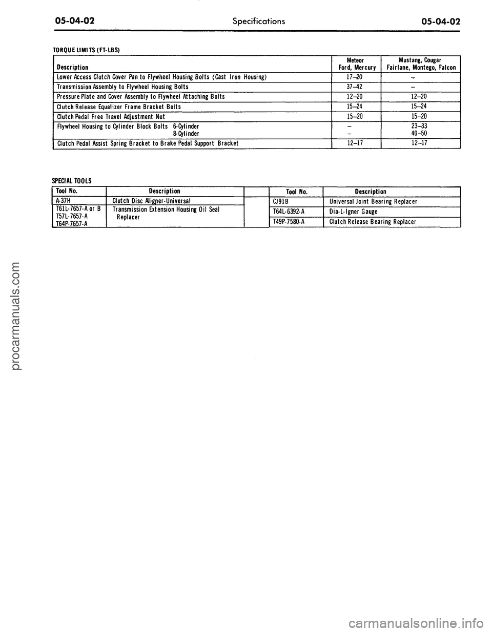
TORQUE LIMITS (FT-LBS)
Description
Lower Access Clutch Cover Pan to Flywheel Housing Bolts (Cast Iron Housing)
Transmission Assembly to Flywheel Housing Bolts
Pressure Plate and Cover Assembly to Flywheel Attaching Bolts
Clutch Release Equalizer Frame Bracket Bolts
Clutch Pedal Free Travel Adjustment Nut
Flywheel Housing to Cylinder Block Bolts
6-Cylinder
8-Cylinder
Clutch Pedal Assist Spring Bracket to Brake Pedal Support Bracket
Meteor
Ford,
Mercury
17-20
37-42
12-20
15-24
15-20
_
12-17
Mustang,
Cougar
Fairlane, Montego, Falcon
-
-
12-20
15-24
15-20
23-33
40-50
12-17
SPECIAL TOOLS
Tool No.
A-37H
T61L-7657-Aor B
T57L-7657-A
T64P-7657-A
Description
Clutch Disc Aligner-Universal
Transmission Extension Housing Oil Seal
Replacer
Tool No.
CJ91B
T64L-6392-A
T49P-7580-A
Description
Universal Joint Bearing Replacer
Dia-L-lgner Gauge
Clutch Release Bearing Replacerprocarmanuals.com
Page 267 of 413

06-01-01
06-01-01
ual Shift
GROUP
6
PART
6-1
PAGE
General Transmission Service
06-01-01
PART 6-2
Ford Design Three-Speed
Transmission
06-02-01
PART 6-3
Ford Design Four-Speed
Transmission
PART
6-4
Specifications
PAGE
.06-03-01
.06-04-01
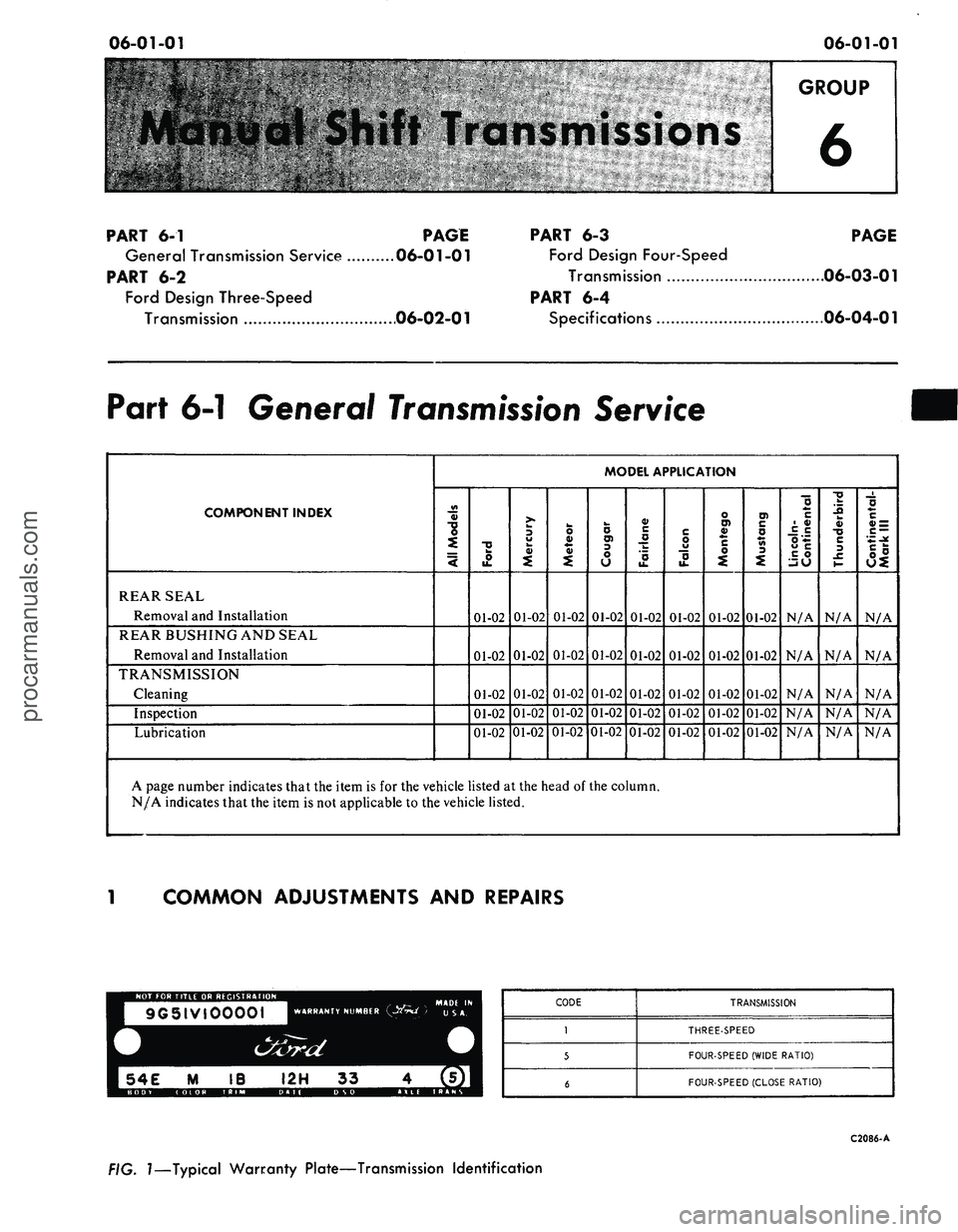
Part 6-1 General
Transmission
Service
COMPONENT INDEX
REAR SEAL
Removal and Installation
REAR BUSHING AND SEAL
Removal and Installation
TRANSMISSION
Cleaning
Inspection
Lubrication
MODEL APPLICATION
All
Models
Ford
01-02
01-02
01-02
01-02
01-02
Mercury
01-02
01-02
01-02
01-02
01-02
Meteor
01-02
01-02
01-02
01-02
01-02
Cougar
01-02
01-02
01-02
01-02
01-02
Fairlane
01-02
01-02
01-02
01-02
01-02
Falcon
01-02
01-02
01-02
01-02
01-02
Montego
01-02
01-02
01-02
01-02
01-02
Mustang
01-02
01-02
01-02
01-02
01-02
Lincoln-
Continental
N/A
N/A
N/A
N/A
N/A
Thunderbird
N/A
N/A
N/A
N/A
N/A
Continental-
Mark
III
N/A
N/A
N/A
N/A
N/A
A page number indicates that the item
is for
the vehicle listed
at
the head
of
the column.
N/A indicates that the item
is
not applicable
to
the vehicle listed.
COMMON ADJUSTMENTS
AND
REPAIRS
54E
M IB I2H 33
CODE
1
5
6
TRANSMISSION
THREE-SPEED
FOUR-SPEED (WIDE RATIO)
FOUR-SPEED (CLOSE RATIO)
C2086-A
FIG.
1—Typical
Warranty Plate—Transmission Identification
procarmanuals.com
Page 268 of 413

06-01-02
General Transmission Service
06-01-02
REAR SEAL REPLACEMENT
1.
Remove the drive shaft.
2.
Remove the seal from the exten-
sion housing with the tool shown in
Fig. 2.
3.
Install the new seal in the exten-
sion housing with the tool shown in
Fig. 3.
4.
Install the drive shaft.
.REAR OIL SEAL
Tool-T61L-7657-A
EXTENSION HOUSING
C 1830.A
FIG. 3—Installing Extension
Housing Seal
Too/-7J75-AB
Tool-TSOT-lOO-A
FIG. 2—Removing Extension Housing Seal
EXTENSION HOUSING
Tool-T52L-7000-GAE
or 7000-G
C1O28-D
FIG. 4—Removing Extension
Housing Bushing and Seal
EXTENSION HOUSING
D
1927. A
Tool—T57P-7697-B
57-G
BUSHING
C 1832.A
FIG. 5—Installing Extension
Housing Bushing
REAR BUSHING AND SEAL
REMOVAL AND INSTALLATION
1.
Remove the drive shaft from the
vehicle.
2.
Insert the tool shown in Fig. 4
into the extension housing until it
grips on ihe front side of the bushing.
3.
Turn the screw clockwise until
the seal and the bushing are free of
the housing.
4.
Drive a new bushing into the ex-
tension housing with the tool shown in
Fig. 5.
5.
Install a new seal in the housing
as shown in Fig. 3.
6. Install the drive shaft.
LUBRICATION
Lubricant level should be even with
the bottom of the filler hole at the
right side of the transmission case.
CLEANING AND INSPECTION
CLEANING
1.
Wash all parts, except the ball
bearings and seals in a suitable clean-
ing solvent. Brush or scrape all foreign
matter from the parts. Be careful not
to damage any parts with the scraper.
Do not clean, wash or soak transmis-
sion seals in cleaning solvents. Dry all
parts with compressed air.
2.
Rotate the ball bearings in a
cleaning solvent until all lubricant is
removed. Hold the bearing assembly
to prevent it from rotating and dry it
with compressed air.
3.
Lubricate the bearings with ap-
proved transmission lubricant and
wrap them in a clean, lint-free cloth
or paper until ready for use.
4.
Clean the magnet welded to the
bottom of the case with kerosene or
mineral spirits.
INSPECTION
1.
Inspect the transmission case for
cracks, worn or damaged bearings
bores,
damaged threads or any other
damage that could affect the opera-
tion of the transmission.
2.
Inspect the front face of the case
for small nicks or burrs that could
cause misalignment of the transmis-
sion with the flywheel housing. Re-
move all small nicks or burrs with a
fine stone.
3.
Replace a cover that is bent or
distorted. Make sure that the vent
hole in the cover is open.
4.
Check the condition of the shift
levers, forks, shift rails and the lever
and shafts.
5.
Examine the ball bearing races
for cracks, wear or roughness. Inspect
the balls for looseness, wear, end play
or other damage. Check the bearings
for looseness in the bores. If any of
these conditions exist, replace the
bearings.
6. Replace roller bearings that are
broken, worn or rough.
7.
Replace the countershaft (clust-
er) gear if the teeth are chipped, brok-
en or worn. Replace the countershaft
if it is bent, scored or worn.
8. Replace the reverse idler gear or
sliding gear if the teeth are chipped,
worn or broken. Replace the idler
gear shaft if bent, worn or scored.
9. Replace the input shaft and gear
if the splines are damaged or if the
teeth are chipped, worn or broken. If
the roller bearing surface in the bore
of the gear is worn or rough, or if the
cone surface is damaged, replace the
gear and the gear rollers.
10.
Replace all other gears that areprocarmanuals.com
Page 269 of 413

06-01-03
General Transmission Service
06-01-03
chipped, broken or worn.
11.
Check the synchronizer sleeves
for free movement on their hubs.
Make sure that the alignment marks
(etched marks) are properly indexed.
12.
Inspect the synchronizer block-
ing rings for widened index slots,
rounded clutch teeth and smooth in-
ternal surfaces (must have machined
grooves). With the blocker ring on the
cone,
the distance between the face of
the blocker ring and the clutch teeth
on the gear must not be less than
0.010 inches.
13.
Replace the speedometer drive
gear if the teeth are stripped or dam-
aged. Make certain to install the cor-
rect size replacement gear.
14.
Replace the output shaft if
there is any evidence of wear or if any
of the splines are damaged.
15.
Inspect the bushing and the seal
in the extension housing. Replace
them if they are worn or damaged.
The bushing and/or seal should be re-
placed after the extension housing has
been installed on the transmission.
16.
Replace the seal in the input
shaft bearing retainer.
17.
Replace the seals on the cam
and shafts.procarmanuals.com
Page 270 of 413

06-02-01
Ford Design Three Speed Transmission
06-02-01
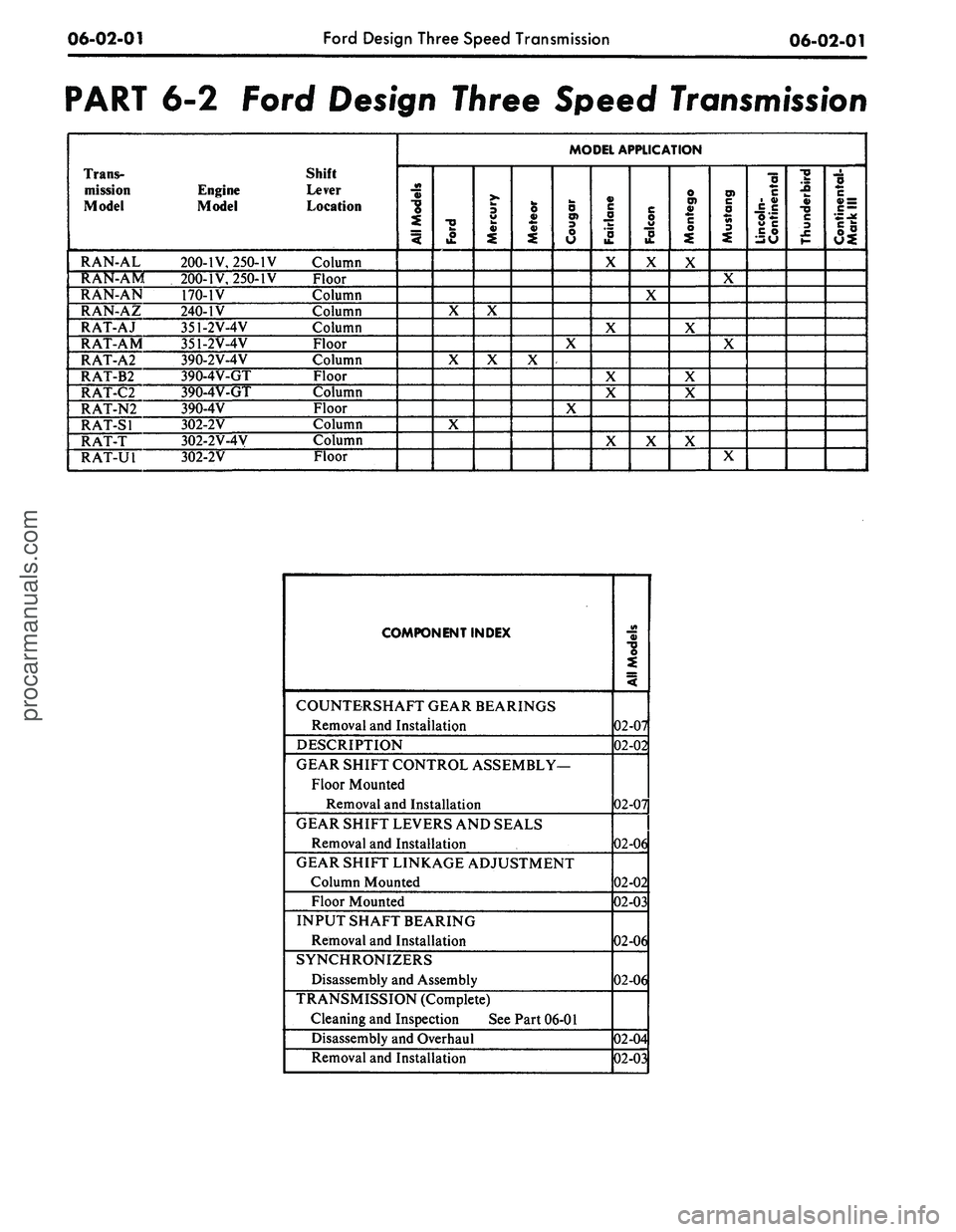
PART 6-2 Ford Design Three Speed
Transmission
Trans-
mission
Model
RAN-AL
RAN-AM
RAN-AN
RAN-AZ
RAT-AJ
RAT-AM
RAT-A2
RAT-B2
RAT-C2
RAT-N2
RAT-SI
RAT-T
RAT-U1
Engine
Model
200-IV, 250-IV
200-IV, 250-IV
170-1V
240-IV
351-2V-4V
351-2V-4V
390-2V-4V
390-4V-GT
390-4V-GT
390-4V
302-2V
302-2V-4V
302-2V
Shift
Lever
Location
Column
Floor
Column
Column
Column
Floor
Column
Floor
Column
Floor
Column
Column
Floor
MODEL APPLICATION
All
Models
Ford
X
X
X
Mercury
X
X
Meteor
X
Cougar
X
X
Fairiane
X
X
X
X
X
Falcon
X
X
X
Montego
X
X
X
X
X
Mustang
X
X
X
Lincoln-
Continental
Thunderbird
Continental-
Mark
III
COMPONENT INDEX
COUNTERSHAFT GEAR BEARINGS
Removal and Installation
DESCRIPTION
GEAR SHIFT CONTROL ASSEMBLY—
Floor Mounted
Removal and Installation
GEAR SHIFT LEVERS AND SEALS
Removal and Installation
GEAR SHIFT LINKAGE ADJUSTMENT
Column Mounted
Floor Mounted
INPUT SHAFT BEARING
Removal and Installation
SYNCHRONIZERS
Disassembly and Assembly
TRANSMISSION (Complete)
Cleaning and Inspection See Part 06-01
Disassembly and Overhaul
Removal and Installation
AH
Models
02-07
02-02
02-07
02-06
02-02
02-03
02-06
02-06
02-04
02-03
procarmanuals.com
Page 271 of 413

06-02-02
Ford Design Three Speed Transmission
06-02-02
DESCRIPTION
DESCRIPTION
The RAN and RAT Model three-
speed transmission (Fig. 1) are used
on models having 170, 200, 240, 250,
302,
351 and 390 C.I.D. engines. The
specifications of this section, Part 6-4,
lists the transmission model numbers
and vehicles in which they are used.
A transmission service identification
tag is located on the right side of the
case at the front (Fig. 2). The first
line on the tag will show the transmis-
sion model and service identification
code when required. The second line
will show the transmission serial num-
ber. Additionally, a driveline compo-
nent identification tag is attached to
the upper right side of the transmis-
sion case.
This transmission is of the fully
synchronized type, with all gears ex-
cept the reverse gear and sleeve being
in constant mesh. All forward-speed
changes are accomplished with syn-
chronizer sleeves.
The forward-speed gears are
helical-cut and are in constant mesh.
Gears used in the reverse gear train
are spur-cut and are not synchronized.
C2O87-A
FIG.
1—Three-Speed
Transmission—Typical
TRANS.
MODEL
SERIAL
NO.
C 2089-A
FIG.
2—Transmission
Identification
Tag
IN-VEHICLE ADJUSTMENTS
AND
REPAIRS
GEAR SHIFT LINKAGE
ADJUSTMENT—COLUMN
MOUNTED
1. Place the gear shift lever in the
neutral position.
2.
Loosen the two gear shift rod
adjustment nuts.
3.
Check shift levers on transmis-
sion to be in neutral position.
4.
Insert a 3/16-inch diameter
alignment tool through the first and
reverse gear shift lever, the second and
third gear shift lever and both holes
in the lower casting (Fig. 3). An align-
ment tool can be made from 3/16
inch drill rod bent to an L shape.
The extensions should be 1 inch and 2
inches from the elbow. The short end
of the tool should be inserted into the
alignment holes.
5.
Tighten the two gear shift rod
adjustment nuts.
6. Remove the alignment tool from
the levers.
7.
Start the engine and shift the se-
lector lever to each position to make
sure it operates freely.
FIG.
3—Gearshift
Linkage Adjustment—Typicalprocarmanuals.com
Page 272 of 413

06-02-03
Ford Design Three Speed Transmission
06-02-03
STOP
PIN
GROMMET
Tool -
T67P.7347.A
GROMMET
LEVER
CONTROL ROD REMOVAL
^S.
GROMMET INSTALLATION
SET STOP PIN SO THAT THE GROMMET
Tool
-
T67P.734LA
AND
SHIFT ROD ARE PROPERLY SEATED
OMMET—^
SEATED
\
CONTROL ROD INSTALLATION
CONTROL ROD
STOP
PIN
FIG. 4—Removing
or
Installing Shift Linkage Grommet
GEAR SHIFT LINKAGE
ADJUSTMENT—FLOOR MOUNTED
1.
Loosen
the
three shift linkage
adjustment nuts. Install
a 1/4
inch
di-
ameter alignment pin through the con-
trol bracket and lever alignment holes
shown
in Fig. 18.
2.
Tighten
the
three linkage adjust-
ment nuts
and
then remove
the
align-
ment
pin.
3.
Check
the
gear shift lever
for a
smooth crossover.
COLUMN-MOUNTED
SHIFT LINKAGE
GROMMET REMOVAL
AND
INSTALLATION
The column-mounted shift lever
as-
sembly incorporates
an oil
impregnat-
ed plastic grommet
in the
end
of
each
lever
arm. A
special tool T67P-
7341-A
is
required
to
install the grom-
met
in the
shift lever,
and to
install
the shift linkage
rod
into
the
grom-
met. Remove
and
install
the
grommet
as follows:
1.
Place
the
lower
jaw of the
tool
between
the
shift lever
and the
shift
rod.
Position
the
stop
pin
against
the
end
of the
shift
rod
(Fig.
4)
and force
the
rod out of the
grommet. Remove
the grommet from
the
shift lever
by
cutting
off the
large shoulder with
a
sharp knife. The groin met must
be re-
moved from
the
shift lever
and a new
one installed each rime
'he rod is
dis-
connected.
2.
Before installing
a
new grommet,
C 2090-A
adjust
the
stop
pin as
necessary
to
properly install
the
grommet and coat
the outside
of
the grommet with lubri-
cant. Then, place
the
grommet
on the
stop
pin and
force
it
into
the
shift
lever hole. Turn
the
grommeit several
times
to be
sure
it is
properly seated.
3.
Readjust
the
stop
pin to a
length
which
is
sufficient
to
install
the
shift
rod into
the
grommet
(Fig.
4).
If
the
pin height
is not
adjusted,
the
shift
rod
may be
pushed
too far
through
the grommet causing damage
to the
grommet retaining
lip.
4.
With
the pin
height properly
ad-
justed, position
the
shift
rod on the
tool
and
force
the rod
into
the
grom-
met until
the
groove
in the rod
seats
on
the
inner retaining
lip of
the grom-
met.
REMOVAL AND INSTALLATION
REMOVAL
1.
Raise
the
vehicle
on a
hoist.
2.
Mark
the
drive shaft
so
that
it
may
be
installed
in the
same relative
position. Disconnect
the
drive shaft
from
the
rear U-joint flange.
3.
Slide
the
front
of the
drive shaft
out
of the
transmission extension
housing
and off the
output shaft
In-
sert
the
tool shown
in (Fig. 2),
Part
6-1 into the extension housing
to
pre-
vent
the
lubricant from leaking
out of
the transmission.
4.
Remove
the cap
screw
and
lock
washer that secures
the
speedometer
cable retainer
to the
extension hous-
ing. Pull
the
speedometer cable
out of
the extension housing.
5.
On
vehicles equipped with
a
column-mounted gear shift selector,
remove
the
shift rods from
the
shift
levers
at
the transmission. On vehicles
equipped with
a
floor-mounted gearprocarmanuals.com