Page 345 of 413

07-03-05
FMX Transmission
07-03-05
IN-VEHICLE ADJUSTMENTS AND REPAIRS
CONTROL LINKAGE
ADJUSTMENTS
The transmission control linkage
adjustments should be performed in
the order in which they appear in this
section of the manual.
THROTTLE AND
DOWNSHIFT LINKAGE
ADJUSTMENTS
Adjusting the throttle linkage is im-
portant to be certain the throttle and
kickdown systems are properly adjust-
ed. The kickdown system should come
in when the accelerator is pressed
through detent, and not before detent.
Refer to Group 10 for detailed
throttle and downshift linkage adjust-
ment procedures.
MANUAL LINKAGE
ADJUSTMENT
COLUMN SHIFT
1.
Place the selector lever in the D
position tight against the stop.
2.
Loosen the shift rod adjusting
nut at point A (Fig. 4 or 5).
3.
Shift the manual lever at the
transmission into the D detent posi-
tion, third from the rear.
4.
Make sure that the selector lever
has not moved from the D stop, then
tighten the nut at point A to 10-20 ft-
lbs.
5.
Check the pointer alignment and
the transmission operation for all se-
lector lever detent positions.
CONSOLE SHIFT
1.
Position the transmission selec-
tor lever in D position.
2.
Raise the vehicle and loosen the
manual lever shift rod retaining nut
(Fig. 6 or 7). Move the transmission
manual lever to the D position, fourth
detent position from the back of the
transmission.
3.
With the transmission selector
lever and manual lever in the D posi-
tions,
torque the attaching nut 10 to
20 ft-lbs.
4.
Check the operation of the trans-
mission in each selector lever position.
COLUMN SHIFT LEVER
€>
TRANSMISSION
MANUAL LEVER
FIG. 4—Manual Linkage—Column Shift—Ford-Mteor
D2024-A
FIG. 5—Manual Linkage—Column Shift—Fairlane-Montego
NEUTRAL START SWITCH
ADJUSTMENT
CONSOLE SHIFT
On vehicles equipped with a
column-mounted neutral start switch,
refer to Part 7-1, Section 2, for the
adjustment procedures.
FAIRLANE-MONTEGO
1.
With the manual linkage proper-
ly adjusted, check the starter en-
gagement circuit in all positions. The
circuit must be open in all drive posi-
tions and closed only in park and neu-
tral.
2.
Remove the selector lever handle
from the lever.
3.
Remove the trim panel from the
top of the console.
4.
Remove the cover and dial indi-
cator as an assembly.
5.
Remove the four screws that se-
cure the selector lever retainer to the
selector lever housing. Lift the retainer
from the housing.
6. Loosen the two combination
starter neutral and back-up light
switch attaching screws (Fig. 8).
7.
Move the selector lever back and
forth until the gauge pin (No. 43 drill)
can be fully inserted into the gauge
pin holes (Fig. 8).
8. Place the transmission selector
lever firmly against the stop of the
neutral detent position.procarmanuals.com
Page 346 of 413
07-03-06
FMX Transmission
07-03-06
BUTTON-7C489
TRANSMISSION
MANUAL LEVER
MANUAL LINKAGE
ROD-7340
HANDLE-7217
MANUAL LINKAGE
ROD-7340
BUSHING-7343
FIG.
6—Manual
Linkage—Console Shift—Fairlane-Montego
D2025-A
PLUG-7256
SELECTOR LEVER
HOUSING AND LEVER
ASSEM3LY-7C453
,'
SEAL-7C370
ENGAGE FLATS OF STUD
IN
SLOT
OF
ROD BEFORE APPLYING TORQUE
NUT
—^
MANUAL LINKAGE ROD-7326
HANDLE-7217
BUTTON-7C489
DIAL HOUSING
ASSEMBLY-7E034
POINTER 3ACK-UP
SHIELD
D2026-A
FIG.
7—Manual
Linkage—Console Shift—Mustang-Cougarprocarmanuals.com
Page 347 of 413

NEUTRAL START
SWITCH
ADJUSTMENT
SCREWS
D 1759-A
FIG. 8—
Neutral
Start Switch-
Console Shift—Fairlane-Montego
9. Slide th")
07-03-07
FMX Transmission
07-03-07
Gauge Pin
(No.
43 Drill)
NEUTRAL START
SWITCH
ADJUSTMENT
SCREWS
D 1759-A
FIG. 8—
Neutral
Start Switch-
Console Shift—Fairlane-Montego
9. Slide the combination starter
neutral and back-up light switch for-
ward or rearward as required, until
the switch actuating lever contacts the
selector lever.
10.
Tighten the switch attaching
screws and remove the gauge pin.
Check for starting in the park posi-
tion.
11.
Turn the ignition key to the
ACC position and place the selector
lever in the reverse position and check
the operation of the back-up lights.
Turn the key off.
12.
Position the selector lever re-
tainer to the selector lever housing.
Install the four attaching screws.
13.
Install the cover and dial indi-
cator.
14.
Install the trim panel on the top
of the console. Install the selector
lever handle.
MUSTANG-COUGAR
1.
With the manual linkage proper-
ly adjusted and the engine turned off,
place the selector lever in the N (Neu-
tral) position. Then, shift the selector
lever from neutral to 1, to P (park)
and back to neutral. Shifting the se-
lector lever through this shift pattern
should adjust the switch automatical-
ly. If not, adjust it manually as fol-
lows:
2.
With the selector lever in neu-
tral,
remove the selector lever handle
attaching screw and remove the
handle (Fig. 7).
3.
Remove the dial housing attach-
ing screws and remove the housing.
4.
Remove the two pointer back-up
shield attaching screws and remove
the shield.
NEUTRAL START SWITCH
AND HARNESS ASSEMBLY
32027-A
FIG. 9—Neutral Start Switch—Console Shift—Mustang-Cougar
5.
Remove the two screws securing
the neutral start switch to the selector
lever housing.
6. Lift the switch from the housing
and move the actuator lever all the
way to the left. Then, return the actu-
ator lever to the neutral position as
shown in Figure 9.
7.
Position the neutral switch as-
sembly to the selector lever housing,
and secure with the two attaching
screws.
8. Place the selector lever in the P
(Park) position and check the opera-
tion of the switch. The engine should
start with the selector lever in the
park position. If the engine does not
start, replace the switch. Refer to the
Neutral Start Switch Replacement
procedures in this section.
9. Install the pointer back-up shield
on the housing and lever assembly.
10.
Install the dial housing on the
selector lever housing assembly.
11.
Install the selector lever.'handle.
NEUTRAL START SWITCH
REPLACEMENT-
CONSOLE SHIFT
On vehicles equipped with a
column-mounted neutral start switch,
refer to Part 7-1, Section 2, for the
replacement procedures.
FAIRLANE-MONTEGO
1.
Remove the selector lever handle
from the lever.
2.
Remove the trim panel from the
top of the console.
3.
Remove the cover and dial indi-
cator as an assembly.
4.
Remove the four screws that se-
cure the selector lever retainer to the
selector lever housing. Lift the retainer
from the housing.
5.
Remove the two screws securing
the neutral start switch to the selector
lever housing. Disconnect the neutral
start switch wires at the plug connec-
tor and remove the switch.
6. Position the neutral start switch
to the selector lever housing and in-
stall the two attaching screws.
7.
With the selector lever in neu-
tral,
move the selector lever back and
forth until the gauge pin (No. 43 drill)
can be fully inserted into the gauge
pin holes (Fig. 8).
8. Place the transmission selector
lever firmly against the stop of the
neutral detent position.
9. Slide the combination starter
neutral and back-up light switch for-
ward or rearward as required, until
the switch actuating lever contacts the
selector lever.
10.
Tighten the switch attaching
screws and remove the gauge pin.
11.
Connect the neutral start switch
wires to the plug connector and check
for starting in the park position.
12.
Position the selector lever re-
tainer to the selector lever housing.
Install the attaching screws.
13.
Install the cover and dial indi-
cator.procarmanuals.com
Page 348 of 413

07-03-08
FAAX Transmission
07-03-08
14.
Install the trim panel on the top
of the console. Install the selector
lever handle.
MUSTANG-COUGAR
1.
Place the transmission selector
lever in the N (Neutral) position.
2.
Raise the vehicle and remove the
manual lever control rod attaching nut
(Fig. 7).
3.
Lower the vehicle and remove
the selector lever handle attaching
screw and the handle.
4.
Remove the dial housing attach-
ing screws and the housing.
5.
Disconnect the dial indicator
light.
6. Disconnect the neutral start
switch and dial indicator light wires
from their connectors at the dash
panel.
7.
Remove the four selector housing
and lever assembly attaching bolts.
Remove the selector lever and housing
assembly.
8. Remove the two pointer back-up
shield attaching screws and remove
the shield.
9. Remove the two screws securing
the neutral start switch to the selector
lever housing. Push the neutral start
switch harness plug inward and re-
move the switch and harness assembly
(Fig. 9).
10.
Before installing the new
switch, hold it with the wires facing
downward and move the actuator
lever all the way to the left. Then, re-
turn the actuator lever to the neutral
position as shown in Figure 9.
11.
Position the harness and neutral
switch assembly in the selector lever
housing. Secure with the two attach-
ing screws.
12.
Install the pointer back-up
shield on the housing and lever assem-
bly.
13.
Position the selector lever and
housing assembly on the console and
install the attaching bolts.
14.
Connect the dial indicator light.
15.
Connect the neutral start switch
and dial indicator light wires to their
respective connectors at the dash
panel.
16.
Install the dial housing on the
selector lever housing assembly.
17.
Install the selector lever handle.
18.
Raise the vehicle and secure the
manual lever control rod to the selec-
tor lever arm.
19.
Lower the vehicle.
20.
Place the selector lever in the
park position and check the operation
of the switch.
DETENT PAWL
LOCK
NUT
DETENT PAWL
ADJUSTMENT SCREW
DETENT PLATE
D 1644-A
FIG.
10—Typical Selector Lever Detent Pawl Adjustment
SELECTOR LEVER
REPLACEMENT—CONSOLE
SHIFT—FAIRLANE
AND
MONTEGO
1.
Raise the vehicle on a hoist or
jack stands.
2.
Remove the retainer that secures
the manual linkage rod to the lower
end of the manual lever (Fig. 6).
3.
Remove the flat washer and two
insulator washers and disconnect the
rod from the arm.
4.
Working from inside of the vehi-
cle,
remove the selector lever handle
attaching screw. Lift the handle off
the selector lever.
5.
Remove the console trim panel
from the top of the console. Remove
the console retaining screws and re-
move the console.
6. Remove the cover and dial indi-
cator as an assembly.
7.
Remove the four screws that se-
cure the selector lever retainer to the
selector lever housing. Lift the retainer
from the housing.
8. Disconnect the neutral start
switch wires at the plug connector.
Disconnect the bulb socket from the
selector lever housing.
9. Remove the three bolts that se^
cure the selector lever control housing
to the console. Lift the selector lever
housing from the console.
10.
Remove the selector lever to
housing attaching nut. Remove the
lever from the housing.
11.
Install the selector lever in the
housing and install the attaching nut.
Torque the nut to 20 to 25 ft-lbs.
12.
Install the selector lever handle.
13.
Position the selector lever as
shown in Figure 10. With a feeler
gauge,
check the clearance between
the detent pawl and plate. The clear-
ance should be 0.005 to 0.010 inch. If
necessary adjust the height of the de-
tent pawl as shown in Figure 10.
14.
Remove the handle from the se-
lector lever.
15.
Position the selector lever hous-
ing in the console and install the three
attaching bolts. Do not tighten the at-
taching bolts at this time.
16.
Connect the bulb socket to the
selector lever housing and the neutral
start switch wires to the plug connec-
tor.
17.
Position the selector lever re-
tainer to the selector lever housing.
Install the four attaching screws.
18.
Install the cover and dial indi-
cator.
19.
Place the console in position
and install the retaining bolts. Tighten
the selector lever housing attaching
bolts.
20.
Position the console trim panel
and secure it with the attaching
screws.
21.
Install the handle and the but-
ton on the selector lever. Secure the
handle with the set screw.
22.
Secure the manual linkage rod
to the arm with two insulating wash-
ers,
a flat washer and a retainer (Fig.
6).
23.
Adjust the linkage as required.
Lower the vehicle.
MUSTANG-COUGAR
1.
Raise the vehicle and remove the
manual lever control rod attaching nut
(Fig. 7).
2.
Lower the vehicle, remove the se-
lector lever handle attaching screw.
3.
Remove the dial housing attach-
ing screws and the housing.procarmanuals.com
Page 349 of 413

07-03-09
FMX Transmission
07-03-09
4.
Remove the pointer back-up
shield attaching screws and the shield.
5.
Disconnect the dial indicator
light.
6. Disconnect the neutral start
switch and dial indicator light wires
from their connectors at the dash
panel.
7.
Remove the selector housing and
lever assembly attaching bolts. Re-
move the selector lever and housing.
8. Remove the selector lever to
housing attaching nut. Remove the
lever from the housing.
9. Install the selector lever in the
housing and install the attaching nut.
Torque the nut to 20 to 25 ft-lbs.
10.
Install the selector lever handle.
11.
Position the selector lever as
shown in Figure 10. With a feeler
gauge check the clearance between the
detent pawl and plate. The clearince
should be 0.005 to 0.010 inch. If nec-
essary, adjust the height of the detent
pawl as shown in Figure 10.
12.
Remo"~ the handle from tte se-
lector lever.
13.
Install the selector housing and
lever assembly as shown in Figure 4.
Torque the attaching bolts 4-6 ft-lbs.
14.
Connect the dial indicator light.
15.
Connect the neutral start switch
and dial indicator light wires to their
respective connectors at the dash
panel.
16.
Install the pointer back-up
shield and tighten the attaching
screws.
17.
Install the selector lever handle
and tighten the attaching screw.
18.
Position the selector lever in the
D position.
19.
Raise the vehicle. Install the
transmission manual lever rod to the
selector lever. Adjust the manual link-
age.
20.
Lower the vehicle and check the
transmission operation in each selec-
tor lever detent position.
BAND ADJUSTMENTS
FRONT BAND
ADJUSTMENT
1.
Drain the fluid from the trans-
mission by loosening the pan attach-
ing bolts starting at the rear of the
pan and working toward the front.
When most of the fluid has drained
from the pan, remove the remainder
of the attaching bolts. Use a clean
drain can equipped with a 100-mesh
screen if the fluid is to be reused.
Too/—
7225-C-13B
/A
-inch
Spacer
FRONT SERVO
ACTUATING LEVER
D 2048-A
FIG.
7
7—Adjusting Front Band—
Typical
2.
Remove the pan, then remove
the fluid filter and clip from the trans-
mission. Clean the inside of the pan.
Remove all gasket material from the
pan and pan mounting face of the
case.
3.
Loosen the front servo adjusting
screw lock nut.
4.
Pull back on the actuating rod,
and insert the 1/4 inch spacer between
the adjusting screw and servo piston
stem (Fig. 11). Tighten the adjusting
screw to 10 in-lbs. torque. Remove the
spacer and tighten the adjusting screw
an additional 3/4 turn. Hold the ad-
justing screw stationary and tighten
the lock nut securely.
5.
Install the transmission fluid
screen and clip. Install the pan using a
new gasket.
6. Refill the transmission to the
FULL mark on the dipstick.
7.
Start the engine and engage the
transmission in each drive range to fill
all fluid passages, then place the selec-
tor lever in the P position. Check the
fluid level and add enough fluid to
bring the level above the ADD mark
on the dipstick.
ALTERNATE FRONT
BAND ADJUSTMENT
1.
Drain the fluid from the trans-
mission. If the same fluid is to be
used again in the transmission after
Che band adjustment, filter the fluid
through a 100-mesh screen as it drains
from the transmission. Re-use the
fluid only if it is in good condition.
2.
Remove and thoroughly clean
the pan and screen. Discard the pan
gasket.
3.
Loosen the front servo adjusting
screw locknut two full turns with a
inch Driv
Detail #2
D.tai\
#3
T-Hond/e
Extension
Tool-758L-7195-A
f/2 inch Driv
Detail
#7
Qj-«—
TM-470 TM-82
D1950-A
FIG. 12—Front and Rear Band
Adjusting Tools
9/16-inch wrench. Check the. adjusting
screw for free rotation in the actuating
lever after the lock nut is loosened,
and free the screw if necessary.
4.
Pull the adjusting screw end of
the actuating lever away from the
servo body, and insert the 1/4 inch
spacer (Fig. 12) between the servo pis-
ton stem and the adjusting screw.
5.
Install the socket handle on the
9/16-inch socket.
6. Insert the T-handle extension
through the socket handle and socket,
and install the screwdriver socket on
the T-handle extension.
7.
Place the tool on the adjusting
screw so that the screwdriver socket
engages the screw and the 9/16-inch
socket engages the lock nut.
8. With a torque wrench on the T-
handle extension, tighten the adjusting
screw to 10 in-lbs torque.
9. Remove the spacer and tighten
the adjusting screw an additional 3/4
turn. Hold the adjusting screw station-
ary, and torque the lock nut to speci-
fication.
10.
Place a new gasket on the pan,
and install the screen and pan on the
transmission.
11.
Fill the transmission with fluid.
REAR BAND ADJUSTMENT—
FORD-METEOR
1.
Fold back the floor mat to ex-
pose the right side of the floor pan.
2.
Remove the access hole cover
from the floor pan. Remove all dirt
from the adjusting screw threads, then
oil the threads.
3.
Loosen the rear band adjusting
screw lock nut with the tool shown in
Fig. 13. Using the T-handle portion of
the tool, tighten the adjusting screw
until the wrench overruns.procarmanuals.com
Page 350 of 413

07-03-10
FMX Transmission
07-03-10
Too/-T69P-7B793-A
ADJUSTING SCREW
REAR SERVO \ LOCK NUT
Tool—7795-C
D1329-A
FIG. 13—Adjusting Rear Band—
Ford-Meteor
If
the
screw
is
found
to be
tighter
than
wrench
capacity
(10
ft-lbs
tor-
que),
loosen
the
screw
and
tighten
until
the
wrench
overruns.
4.
Back off the adjusting screw 1
1/2 turns. Hold the adjusting screw
stationary, and tighten the adjusting
screw lock nut to specifications.
Severe damage may result if the ad-
justing screw is not backed off exactly
1 1/2 turns.
ALTERNATE REAR BAND
ADJUSTMENT—
FORD-METEOR
The tool shown in Fig. 12 may be
used to adjust the rear band.
1.
Place the socket holder on the
3/4-inch socket (Fig. 12). Insert the
T-handle extension through the handle
and socket.
2.
Place the 5/ 16-inch 8-point sock-
et on the extension. Place a torque
wrench on the T-handle extension.
3.
Insert the assembled tool in the
access hole so that it engages the ad-
justing screw and the lock nut.
4.
Loosen the adjusting screw lock
nut.
5.
Torque the adjusting screw to 10
ft-lbs.
6. Remove the torque wrench from
the T-handle extension and back off
the adjusting screw exactly 1 1/2
turns.
Severe
damage
may
result
to
the
transmission
if the
adjusting
screw
is
not
backed
off
exactly
11/2
turns.
7.
Hold the adjusting screw station-
ary and tighten the lock nut securely.
REAR BAND ADJUSTMENT—
FAIRLANE, MONTEGO
MUSTANG AND COUGAR
Adjustment of the rear band may
be performed either internally or ex-
ternally. Use the internal band adjust-
ment procedures when making a nor-
mal (in-vehicle) band adjustment. Use
ADJUSTING SCREW
LOCK NUT
I
IN
TorqueWrench REAR SERVO APPLY LEVER
D2028-A
FIG. 14—Adjusting Rear Band—
Fairlane, Montego, Mustang and
Cougar
the external adjustment procedure
only when the transmission has been
removed from the vehicle, or when all
available internal adjustment has been
taken up and a further band adjust-
ment is required.
Internal Band Adjustment
1.
Drain the fluid from the trans-
mission. If the same fluid is to be
used again in the transmission after
the band adjustment, filter the fluid
through a 100-mesh screen as it drains
from the transmission. Re-use the
fluid only if it is in good condition.
2.
Remove and thoroughly clean
the pan and filter. Discard the pan
gasket.
3.
Loosen the rear servo adjusting
screw lock nut.
4.
Pull the adjusting screw end of
the actuating lever away from the
servo body, and insert the spacer tool
shown in Fig. 14 between the servo
accumulator piston and the adjusting
screw.
Be
sure
the
flat
surfaces
of the
tool
are
positioned
squarely
between
the
adjusting
screw
and the
accumula-
tor
piston.
The
tool must
not
touch
the servo
piston
and the
tool
handle
must
not
touch
the
servo
piston
spring
retainer.
5.
Using a torque wrench with an
Allen head socket (Fig. 14), tighten
the adjusting screw to 24 in-lbs tor-
que.
6. Back off the adjusting screw
1-1/2 turns. Hold the adjusting screw
stationary and tighten the adjusting
screw lock nut sequrely. Remove the
spacer tool.
7.
Install the transmission fluid fil-
ter and clip. Install the pan using a
new gasket.
8. Fill the transmission with fluid.
D2029-A
FIG. 15—Rear Servo Lever
Adjusting Screw Dimension—
Fairlane, Montego, Mustang and
Cougar
External Band Adjustment
1.
With the transmission mounted
in a holding fixture, loosen the inter-
nal rear servo adjusting screw lock nut
(Fig. 15).
2.
Set the internal adjusting screw
to the dimension shown in Figure 15.
Tighten the lock nut.
3.
With the internal adjusting screw
properly adjusted, loosen the external
adjusting screw lock nut.
4.
Using a torque wrench with an
Allen head socket, tighten the adjust-
ing screw to 10 ft-lbs torque.
5.
Back off the adjusting screw
1-1/2 turns.
6. Hold the adjusting screw from
turning and torque the lock nut to
specification.
GOVERNOR REPLACEMENT
1.
Raise the vehicle so that the
transmission extension housing is ac-
cessible.
2.
Drain the fluid from the trans-
mission.
3.
Disconnect the drive shaft from
the rear axle and slide the front yoke
out of the extension housing.
4.
Disconnect the speedometer
cable from the extension housing.
5.
Remove the two bolts that secure
the extension housing to the engine
rear support.
6. Remove the nut and bolt that se-
cures the engine rear support to the
crossmember.
7.
Raise the transmission high
enough to provide clearance for the
rear mount.
8. Lift the engine rear support from
the crossmember.
9. Lower the jack until the exten-
sion housing just clears the crossmem-procarmanuals.com
Page 351 of 413

07-03-11
FMX Transmission
07
03-11
GOVERNOR
COMPENSATOR
PRESSURE TUBE
MAIN CONTROL
VALVE TUBE
COUNTERWEIGHT
D 1815-A
FIG. 16—Governor Installed
ber to remove all weight from the
housing.
10.
Loosen the parking brake cable
adjustment nut enough to disconnect
the cables from the equalizer.
11.
Remove the extension housing
attaching bolts. Slide the housing off
the output shaft and remove the gas-
ket. When removing
the
extension
housing and/or governor, hold
the
output shaft
and
rear support from
moving rearward
to
prevent
the
needle
bearing
and
race from dropping
out of
location.
12.
Remove the governor to coun-
terweight attaching screws. Lift the
governor from the counterweight (Fig.
16).
13.
Lubricate the governor valve
parts with clean transmission fluid.
Make certain that
the
valve moves
freely
in the
valve body bore.
14.
Position the governor valve
body on the counterweight with the
cover facing toward the front of the
vehicle. Install and tighten the two at-
taching screws to the specified torque.
15.
Position a new extension hous-
ing gasket on the rear of the transmis-
sion case.
16.
Slide the extension housing into
place and secure it to the transmission
case with the attaching bolts. Torque
the bolts to specification. With the ex-
tension housing installed, rotate
the
output shaft.
The
shaft must rotate
freely
by
hand.
If the
shaft
is
tight
or
bound
up, it is
likely that
the
needle
bearing
and
race have dropped
out of
location,
in
which case,
the
transmis-
sion must
be
partially disassembled
and
the
bearing
and
race repositioned.
17.
Connect the speedometer cable
to the extension housing.
18.
Raise the transmission high
enough with a jack to position the en-
FRONT SERVO
FLUID TUBES
PRESSURE
REGULATOR
D 1817-A
FIG. 17—Typical Hydraulic Control System
gine rear support on the crossmember.
Secure the support to the crossmem-
ber with attaching bolt.
19.
Lower the transmission and re-
move the jack. Secure the extension
housing to the rear support with the
two attaching bolts.
20.
Connect the parking brake
cables to the equalizer and adjust the
cables as required.
21.
Install the driveshaft.
22.
Fill the transmission to the cor-
rect level with the specified fluid.
OIL
PAN AND
CONTROL
VALVE BODY REPLACEMENT
1. Raise the vehicle so that the
transmission fluid pan is accessible.
2.
Drain the fluid from the trans-
mission by loosening the pan attach-
ing bolts starting at the rear of the
pan and working toward the front.
When most of the fluid has drained
from the pan, remove the remainder
of the attaching bolts. Remove the
pan and gasket. Discard the gasket. If
the same fluid is to be used again in
the transmission, filter the fluid
through a 100-mesh screen before in-
stalling it in the transmission. Re-use
the fluid only if it is in good condi-
tion.
3.
Disconnect the hose from the
vacuum diaphragm unit. Remove the
diaphragm unit using tool FCO-24.
Do
not use any
tools
on the dia-
phragm housing, such
as
pliers, pipe
wrenches,
etc. Do not
allow solvents
to enter
the
diaphragm unit. Remove
the push rod. Remove the fluid screen
retaining clip and the screen.
4.
Remove the fluid filter retaining
clip and the filter.
5.
Remove the two tubes which
connect to the pressure regulator and
the control valve body (Fig. 17).
6. Loosen the front servo attaching
bolts three turns.
7.
Remove the three control valve
body attaching bolts, and lower the
valve body while pulling it off the
front servo tubes. Be carefull not to
damage
the
valve body
or the
tubes.
8.
Before installing the control
valve body, check for a bent manual
valve by rolling it on a flat surface.
9. Install the control valve body by
aligning the front servo tubes with the
holes in the valve body. Shift the man-
ual lever to the 1 detent, and place the
inner downshift lever between the
downshift lever stop and the downshift
valve.
The
manual valve must engage
the actuating
pin in the
manual detent
lever.
10.
Install but do not tighten, the
control valve body attaching bolts.procarmanuals.com
Page 352 of 413

07-03-12
FMX Transmission
07-03-12
11.
Move the control valve body
toward the center of the case until the
clearance is less than 0.050 inch, be-
tween the manual valve and the act-
uating pin on the manual detent lever.
12.
Torque the attaching bolts to
specification. Be sure that the rear
fluid filter retaining clip is installed
under the valve body bolt as shown in
Figure 17.
13.
Install the tubes to the pressure
regulator and the control valve body.
14.
Turn the manual valve one full
turn in each manual lever detent posi-
tion. If the manual valve binds against
the actuating pin in any detent posi-
tion, loosen the valve body attaching
bolts and move the body away from
the center of the case. Move the valve
body only enough to relieve the bind-
ing. Torque the attaching bolts and
recheck the manual valve for binding.
15.
Position the push rod in the
bore of the vacuum diaphragm unit.
Using the diaphragm unit as a guide,
insert the push rod into the threaded
opening of the case. Torque the dia-
phragm unit to specification. Connect
the vacuum hose.
16.
Torque the front servo attach-
ing bolts to specification.
17.
Adjust the front band. If the
unit is a model PHB-C, D, E, F, G or
H, adjust the rear band at this time.
18.
Install the fluid filter and the
filter retaining clip.
19.
Position a new fluid pan gasket
on the bottom of the transmission
case,
and install the pan. Torque the
pan screws to specification.
20.
Adjust the rear band on
PHB-A and PHD models.
21.
Fill the transmission with fluid.
If
the
fluid that
was
drained from
the
transmission
is to be
used
again,
filter
the fluid through
a
100-mesh screen
as
it
is
poured back into
the
transmis-
sion.
Re-use
the
fluid only
if it is in
good
condition.
22.
If the control valve body was
replaced, adjust the transmission con-
trol linkage.
PRESSURE REGULATOR
REPLACEMENT
1. Drain the fluid from the trans-
mission, and remove the pan and fluid
filter.
2.
Remove the small compensator
pressure tube and the large control
pressure tube from the control valve
body and the pressure regulator.
3.
Remove the pressure regulator
spring retainer, springs, and spacer.
Maintain pressure
on the
retainer
to
prevent
the
springs from flying
out.
4.
Remove the pressure regulator
attaching bolts and washers, and re-
move the regulator.
5.
Position the replacement regula-
tor body on the transmission case and
install the two attaching bolts. Torque
the bolts to specification.
6. Check the converter pressure and
control pressure valves to be sure the
valves operate freely in the bores.
7.
Install the valve springs, spacer,
and retainer.
8. Install the large control pressure
tube,
and the small compensator pres-
sure tube.
9. Install the fluid filter and the
pan, and fill the transmission to the
correct level with the specified fluid.
FRONT SERVO REPLACEMENT
1. Drain the fluid from the trans-
mission, and remove the pan and fluid
filter.
2.
Remove the vacuum diaphragm
unit.
3.
Loosen the three control valve
body attaching bolts.
4.
Remove the attaching bolts from
the front servo (Fig. 17), hold the
strut with the fingers, and remove the
servo.
5.
To install the front servo, posi-
tion the front band forward in the
case with the end of the band facing
downward. Make sure the front servo
anchor pin is in position in the case
web.
Align the large end of the servo
strut with the servo actuating lever,
and align the small end with the band
end.
6. Rotate the band, strut, and servo
to align the anchor end of the band
with the anchor in the case.
Push the servo body onto the con-
trol valve body tubes.
7.
Install the attaching bolts and
torque to specification.
8. Torque the control valve body
attaching bolts to specification.
Check the clearance between the
manual valve and manual lever actuat-
ing pin as given in Oil Pan and Con-
trol Valve Body Replacement.
9. Adjust the front band.
10.
Install the vacuum diaphragm
unit and rod.
11.
Install the fluid filter and pan,
and fill the transmission with fluid.
12.
Adjust the downshift and manu-
al linkage.
REAR SERVO REPLACEMENT
1. Drain the fluid from the trans-
mission, and remove the pan and fluid
filter.
2.
Remove the vacuum diaphragm
unit.
3.
Remove the control valve body
and the two front servo tubes.
4.
Remove the attaching bolts from
the rear servo, hold the actuating and
anchor struts with the fingers, and re-
move the servo. Remove the servo
dowel on PHB models.
5.
To install the rear servo, position
the servo anchor strut on the servo
band, and rotate the band to engage
the strut.
6. Hold the servo anchor strut in
position with the fingers, position the
actuating lever strut, and install the
servo. Insert the servo dowel on PHB
models.
7.
Install the servo attaching bolts,
and torque them to specification. The
longer bolt must
be
installed
in the
inner bolt
hole.
8.
Install the two front servo tubes
and the control valve body.
Check the clearance between the
manual valve and the manual lever
actuating pin as given above in Oil
Pan and Control Valve Body Replace-
ment.
9. Adjust the rear band.
10.
Install the fluid filter and pan,
and fill the transmission with fluid.
Too/~7?75-AB
7oo/-T50T-JOO-A
78—Removing Extension Housing Seal
D 1927-Aprocarmanuals.com
 1
1 2
2 3
3 4
4 5
5 6
6 7
7 8
8 9
9 10
10 11
11 12
12 13
13 14
14 15
15 16
16 17
17 18
18 19
19 20
20 21
21 22
22 23
23 24
24 25
25 26
26 27
27 28
28 29
29 30
30 31
31 32
32 33
33 34
34 35
35 36
36 37
37 38
38 39
39 40
40 41
41 42
42 43
43 44
44 45
45 46
46 47
47 48
48 49
49 50
50 51
51 52
52 53
53 54
54 55
55 56
56 57
57 58
58 59
59 60
60 61
61 62
62 63
63 64
64 65
65 66
66 67
67 68
68 69
69 70
70 71
71 72
72 73
73 74
74 75
75 76
76 77
77 78
78 79
79 80
80 81
81 82
82 83
83 84
84 85
85 86
86 87
87 88
88 89
89 90
90 91
91 92
92 93
93 94
94 95
95 96
96 97
97 98
98 99
99 100
100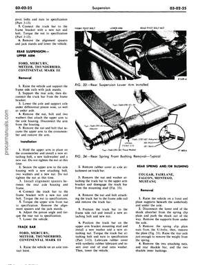 101
101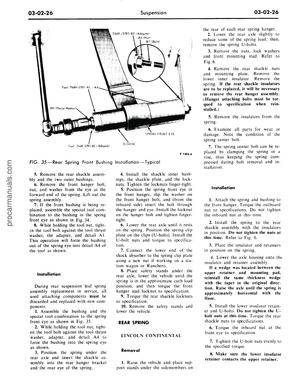 102
102 103
103 104
104 105
105 106
106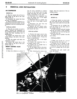 107
107 108
108 109
109 110
110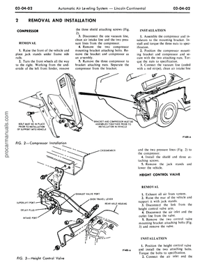 111
111 112
112 113
113 114
114 115
115 116
116 117
117 118
118 119
119 120
120 121
121 122
122 123
123 124
124 125
125 126
126 127
127 128
128 129
129 130
130 131
131 132
132 133
133 134
134 135
135 136
136 137
137 138
138 139
139 140
140 141
141 142
142 143
143 144
144 145
145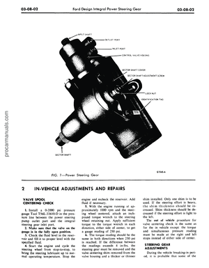 146
146 147
147 148
148 149
149 150
150 151
151 152
152 153
153 154
154 155
155 156
156 157
157 158
158 159
159 160
160 161
161 162
162 163
163 164
164 165
165 166
166 167
167 168
168 169
169 170
170 171
171 172
172 173
173 174
174 175
175 176
176 177
177 178
178 179
179 180
180 181
181 182
182 183
183 184
184 185
185 186
186 187
187 188
188 189
189 190
190 191
191 192
192 193
193 194
194 195
195 196
196 197
197 198
198 199
199 200
200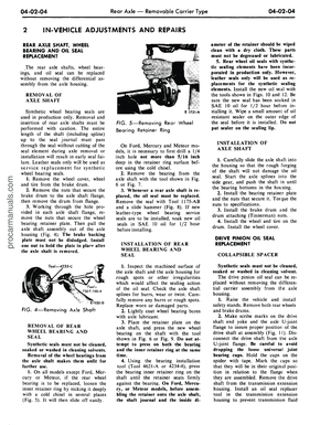 201
201 202
202 203
203 204
204 205
205 206
206 207
207 208
208 209
209 210
210 211
211 212
212 213
213 214
214 215
215 216
216 217
217 218
218 219
219 220
220 221
221 222
222 223
223 224
224 225
225 226
226 227
227 228
228 229
229 230
230 231
231 232
232 233
233 234
234 235
235 236
236 237
237 238
238 239
239 240
240 241
241 242
242 243
243 244
244 245
245 246
246 247
247 248
248 249
249 250
250 251
251 252
252 253
253 254
254 255
255 256
256 257
257 258
258 259
259 260
260 261
261 262
262 263
263 264
264 265
265 266
266 267
267 268
268 269
269 270
270 271
271 272
272 273
273 274
274 275
275 276
276 277
277 278
278 279
279 280
280 281
281 282
282 283
283 284
284 285
285 286
286 287
287 288
288 289
289 290
290 291
291 292
292 293
293 294
294 295
295 296
296 297
297 298
298 299
299 300
300 301
301 302
302 303
303 304
304 305
305 306
306 307
307 308
308 309
309 310
310 311
311 312
312 313
313 314
314 315
315 316
316 317
317 318
318 319
319 320
320 321
321 322
322 323
323 324
324 325
325 326
326 327
327 328
328 329
329 330
330 331
331 332
332 333
333 334
334 335
335 336
336 337
337 338
338 339
339 340
340 341
341 342
342 343
343 344
344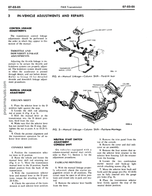 345
345 346
346 347
347 348
348 349
349 350
350 351
351 352
352 353
353 354
354 355
355 356
356 357
357 358
358 359
359 360
360 361
361 362
362 363
363 364
364 365
365 366
366 367
367 368
368 369
369 370
370 371
371 372
372 373
373 374
374 375
375 376
376 377
377 378
378 379
379 380
380 381
381 382
382 383
383 384
384 385
385 386
386 387
387 388
388 389
389 390
390 391
391 392
392 393
393 394
394 395
395 396
396 397
397 398
398 399
399 400
400 401
401 402
402 403
403 404
404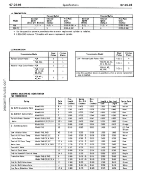 405
405 406
406 407
407 408
408 409
409 410
410 411
411 412
412