Page 153 of 413

03-09-01
Saginaw Design Integral Power Steering Gear
03-09-01
PART 3-9 Saginaw Design
Integral Power Steering Gear
COMPONENT INDEX
STEERING GEAR
Cleaning and Inspection (See Page 03-01)
Description
Disassembly and Assembly
Mesh Load Adjustment
Removal and Installation
Overhaul
MODEL APPLICATION
All
Models
Ford
09-01
09-03
09-01
09-02
09-04
Mercury
N/A
N/A
N/A
N/A
N/A
N/A
Meteor
N/A
N/A
N/A
N/A
N/A
N/A
Cougar
N/A
N/A
N/A
N/A
N/A
N/A
Fairlane
N/A
N/A
N/A
N/A
N/A
N/A
Falcon
N/A
N/A
N/A
N/A
N/A
N/A
Montego
N/A
N/A
N/A
N/A
N/A
N/A
Mustang
N/A
N/A
N/A
N/A
N/A
N/A
Lincoln-
Continental
N/A
N/A
N/A
N/A
N/A
N/A
Thunderbird
N/A
N/A
N/A
N/A
N/\
N/A
Continental-
Mark III
N/A
N/A
N/A
N/A
N/A
N/A
A page number indicates that the item is for the vehicle listed at the head of the column.
N/A indicates that the item is not applicable to the vehicle listed.
DESCRIPTION
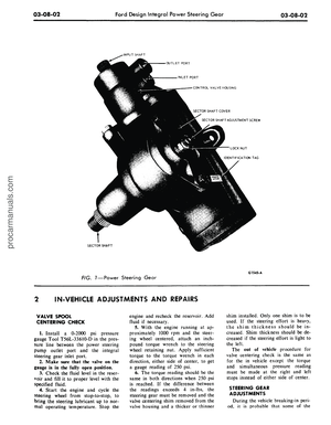
The Rotary Valve Safety power
steering gear operates entirely on dis-
placing fluid to provide hydraulic fluid
pressure assists only when turning. As
the entire gear assembly is always full
of fluid, all internal components of the
gear are immersed in fluid making
periodic lubrication unnecessary. In
addition, this fluid acts as a cushion
to absorb road shocks that may be
transmitted to the driver. All fluid
passages are internal except the pres-
sure and return hoses between the
gear and pump.
The rotary valve provides a smooth
transmission through the driving range
of steering wheel effort. A torsion bar
transmits the road feel to the driver.
Response of the steering gear to effort
applied to the steering wheel has been
greatly increased.
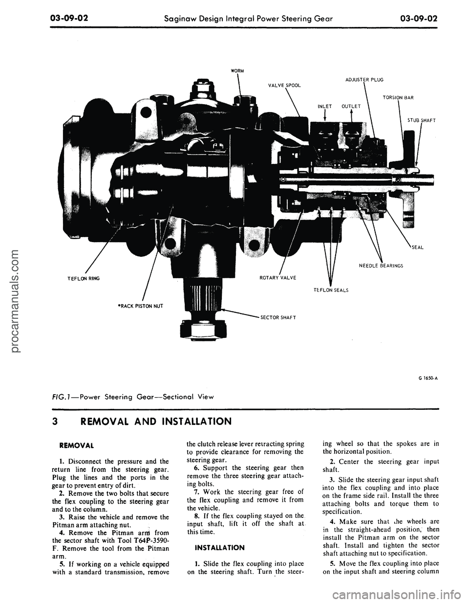
The rack-piston nut is one piece and
is geared to the sector shaft. Lash be-
tween the sector shaft and rack-piston
nut is maintained by an adjusting
screw which is retained in the end o\'
the shaft uear (Eiiz.l).
IN-VEHICLE ADJUSTMENTS AND REPAIRS
During the breaking in period of
the vehicle, it is probable that some
of the factory adjustments will change.
These changes in adjustment do not
necessarily affect the satisfactory op-
eration of the steering gear assembly
and ordinarily do not require re-ad-
justment unless there is excessive lash
or other malfunctioning. The only ad-
justment that should be performed in
the vehicle is the total over center
position load (mesh load) to eliminate
excessive lash between the sector shaft
and rack teeth.
MESH LOAD ADJUSTMENT
1.
Disconnect the Pitman arm from
the sector shaft and remove the steer-
ing wheel hub.
2.
Disconnect the fluid return line
at the reservoir; at the same time cap
the reservoir return line pipe.
3.
Place the end of the return line
in a clean container and cycle the
steering wheel in both directions as
required, to discharge the fluid from
the gear.
4.
Turn the gear 1/2 turn off cen-
ter (either direction). Using a 24 in-
lb torque wrench on the steering wheel
nut, determine the torque required to
rotate the shaft slowly through a 20
degree arc.
5.
Turn the sear back to center and
repeating the method of reading tor-
que as in Step 4, above, loosen the
adjuster lock nut, turn the screw in-
ward with a 7/32-inch Allen wrench
until the reading is equal to 6 in-lbs
in excess of Step 4 above, and retigh-
ten the lock nut while holding the
screw in place.
6. Recheck the readings and re-
place the Pitman arm and the steering
wheel hub.
7.
Connect the fluid return line to
the reservoir and fill the reservoir
with C1AZ-I9582-A Fluid to the
proper level.
procarmanuals.com
Page 154 of 413

03-09-02
Saginaw Design Integral Power Steering Gear
03-09-02
WORM
ADJUSTER PLUG
TORSION BAR
STUB SHAFT
SEAL
NEEDLE BEARINGS
TEFLON RING
TEFLON SEALS
SECTOR SHAFT
FIG.l —
Power
Steering Gear—Sectional View
G 1650-A
REMOVAL
AND
INSTALLATION
REMOVAL
1.
Disconnect
the
pressure
and the
return line from
the
steering gear.
Plug
the
lines
and the
ports
in the
gear to prevent entry of dirt.
2.
Remove the two bolts that secure
the flex coupling
to the
steering gear
and
to
the column.
3.
Raise
the
vehicle
and
remove
the
Pitman arm attaching nut.
4.
Remove
the
Pitman arni from
the sector shaft with Tool T64P-3590-
F.
Remove
the
tool from
the
Pitman
arm.
5.
If
working
on a
vehicle equipped
with
a
standard transmission, remove
the clutch release lever retracting spring
to provide clearance
for
removing
the
steering gear.
6. Support
the
steering gear then
remove
the
three steering gear attach-
ing bolts.
7.
Work
the
steering gear free
of
the flex coupling
and
remove
it
from
the vehicle.
8.
If
the flex coupling stayed
on the
input shaft, lift
it off the
shaft
at
this time.
INSTALLATION
1.
Slide
the
flex coupling into place
on
the
steering shaft. Turn
the
steer-
ing wheel
so
that
the
spokes
are in
the horizontal position.
2.
Center
the
steering gear input
shaft.
3.
Slide the steering gear input shaft
into
the
flex coupling
and
into place
on
the
frame side rail. Install the three
attaching bolts
and
torque them
to
specification.
4.
Make sure that
ihe
wheels
are
in
the
straight-ahead position, then
install
the
Pitman
arm on the
sector
shaft. Install
and
tighten
the
sector
shaft attaching nut to specification.
5.
Move the flex coupling into place
on
the
input shaft
and
steering columnprocarmanuals.com
Page 155 of 413

03-09-03
Saginaw Design Integral Power Steering Gear
03-09-03
shaft and install and tighten the attach-
ing bolts to specification.
6. Connect and tighten the fluid
pressure and the return line to the
steering gear.
7. Fill the power steering pump and
cycle the steering gear. Check for
leaks.
Check the reservoir fluid level
again and add as required.
MAJOR REPAIR OPERATIONS
Disassembly and reassembly of the
unit and the subassemblies must be
made on a clean workbench. As in re-
pairing any hyldraulically operated
unit, cleanliness is of tftfiiost impor-
tance. Therefore, the bench, tools, and
parts must be kept clean at all times.
Thoroughly clean the exterior of the
gear with a suitable solvent and, when
necessary, drain as much of the hy-
draulic fluid from the gear as possible.
DISASSEMBLY INTO
SUB-ASSEMBLIES
1,
Mount the steering gear in a
vise.
(Fig..
2\
2.
Rotate the end plug retaining
ring to place one end of the ring
opposite the hole in the housing.
3.
Working through the hole in the
housing (Fig. 3), unseat the retaining
ring then work it out of the groove
with a screwdriver.
4.
Rotate the input shaft in a coun-
terclockwise direction using a 3/4
inch, 12-point socket wrench to force
the end plug out of the housing. Do
not rotate the shaft any more than
necessary to remove the plug. Further
rotation will allow the balls to fall
from their circuit and allow the rack-
piston to become disengaged from the
sector shaft. Remove the O-ring from
the housing and discard it.
5.
Rotate the input shaft 1/2 turn
in a clockwise direction to draw the
piston inward.
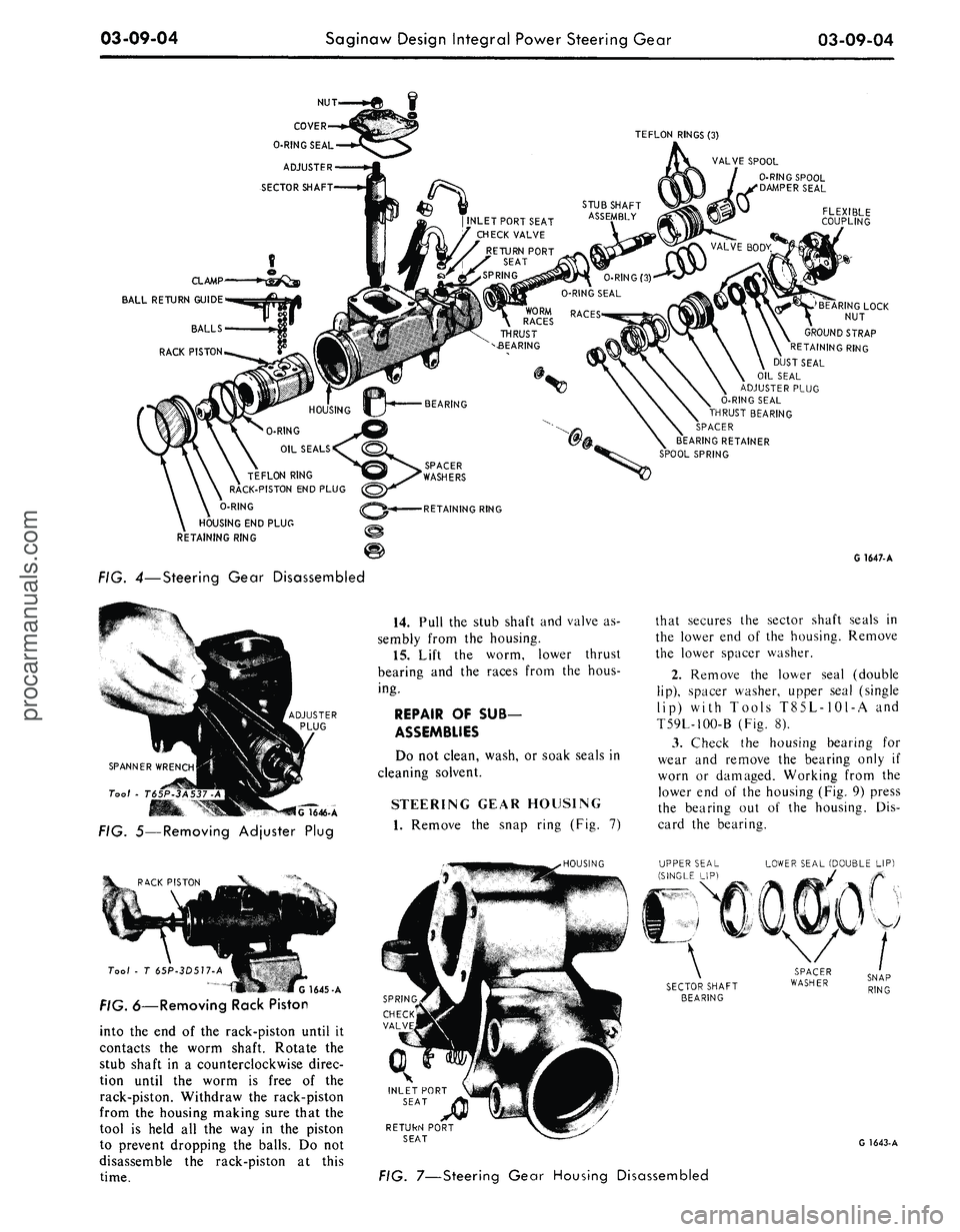
6. Turn the end plug (Fig. 4) count-
erclockwise out of the piston with a
1/2 inch drive extension.
7.
Remove the lock nut from the
sector shaft adjustment screw. Discard
the nut.
8. Remove the four cover attaching
screws. Rotate the sector shaft adjust-
ment screw with an Allen wrench until
the cover is free of the housing. Re-
move the cover and the O-ring. Dis-
card the O-ring.
9. Turn the input shaft as required
to center the sector shaft teeth in the
housing.
10.
Tap the end of the sector shaft
with a soft-faced hammer to free it
from the housing.
11.
Remove the adjuster plug lock
nut.
12.
Remove the adjuster p>ug with
spanner wrench T65P-3A537-A (Fig.
15).
13.
Insert the tool shown ir Fig. 6
LOCK NUT RETUF™ P0RT
INLET PORT
TORSION BAR
STUB SHAFT
SECTOR SHAFT
ADJUSTMENT SCREW
ADJUSTER PLUG
HOUSING
SECTOR SHAFT
G
1649-
A
FIG. 2—Steering Gear
END PLUG
G1648-A
FIG. 3—Removing End Plug
Retaining Rinaprocarmanuals.com
Page 156 of 413

03-09-04
Saginaw Design Integral Power Steering Gear
03-09-04
CLAMP
BALL
RETURN GUIDE
TEFLON
RINGS (3)
VALVE
SPOOL
0-RING SPOOL
SEAL
INLET
PORT SEAT
CHECK
VALVE
RETURN
PORT
SEAT
SPRING
STUB
SHAFT
ASSEMBLY
TEFLON
RING
RACK-PISTON
END PLUG
O-RING
HOUSING
END PLUG
RETAINING
RING
FLEXIBLE
COUPLING
'BEARING
LOCK
NUT
GROUND
STRAP
RETAINING
RING
DUST
SEAL
OIL
SEAL
ADJUSTER
PLUG
O-RING SEAL
THRUST
BEARING
SPACER
BEARING
RETAINER
SPOOL
SPRING
RETAINING
RING
FIG. 4—Steering Gear Disassembled
SPANNER
WRENCH
Tool - T65P-
lG
1646-A
FIG. 5—Removing Adjuster Plug
14.
Pull the stub shaft and valve as-
sembly from the housing.
15.
Lift the worm, lower thrust
bearing and the races from the hous-
ing.
REPAIR
OF SUB-
ASSEMBLIES
Do not clean, wash, or soak seals in
cleaning solvent.
STEERING GEAR HOUSING
1.
Remove the snap ring (Fig. 7)
G
1647-A
that secures the sector shaft seals in
the lower end of the housing. Remove
the lower spacer washer.
2.
Remove the lower seal (double
lip),
spacer washer, upper seal (single
lip) with Tools T85L-1O1-A and
T59L-100-B (Fig. 8).
3.
Check the housing bearing for
wear and remove the bearing only if
worn or damaged. Working from the
lower end of the housing (Fig. 9) press
the bearing out of the housing. Dis-
card the bearing.
.HOUSING
LOWER
SEAL (DOUBLE LIP)
Tool
- T 65P-3D517-A
G
1645-A
FIG. 6—Removing Rack Piston
into the end of the rack-piston until it
contacts the worm shaft. Rotate the
stub shaft in a counterclockwise direc-
tion until the worm is free of the
rack-piston. Withdraw the rack-piston
from the housing making sure that the
tool is held all the way in the piston
to prevent dropping the balls. Do not
disassemble the rack-piston at this
time.
SNAP
RING
INLET
PORT
SEAT
RETUkN
PORT
SEAT
G
1643-A
FIG. 7—Steering Gear Housing Disassembledprocarmanuals.com
Page 157 of 413

03-09-05
Saginaw Design Integral Power Steering Gear
03-09-05
Tool . T59L -100S
FIG. 8—Removing Sector
Shaft Seals
Too/
-
T65P -3576-C
G 1641-A
FIG. 9—Removing Sector
Shaft Bearings
4.
Working from
the
upper
end of
the housing, press
in a new
bearing
until
the
upper
end
is
0.030 inch below
the housing bore. When installing
the
bearing, make sure
it is
pressed
in
from
the
identification
end
(stamped
end).
5.
Lubricate
new
sector shaft seals
(Fig.
7) in
C1AZ-19582-A hydraulic
fluid. Install
the
single
lip
seal first,
then
a
back-up washer. Using special
tool
(Fig. 10),
drive
the
seal
and
wash-
er
in far
enough
to
provide clearance
for
the
other seal
and
back-up washer
and
the
retaining ring.
The
seal must
not bottom
on the end of
the
counter-
bore.
Install
the
double
lip
seal
and
the second back-up washer. Again using
the special tool, drive
the
seal
and
back-up washer
in
only
far
enough
to
provide clearance
for the
retaining
ring. Install
the
sector shaft seal
re-
taining ring with snap ring pliers,
making certian that
the
ring
is
seated
properly.
6.
To
remove
a
damaged port seat,
use
a
5/16-18 inch
U.S.
thread
(coarse)
tap and
turn
it
two
turns into
the seat.
7.
Thread
a
bolt
and nut
with
a
flat
washer into
the
tapped hole
(Fig.
11).
8. Hold
the
bolt from turning
and
tighten
the nut to
extract
the
seat.
Discard
the
seat.
9. Remove
the
check valve
and
spring from
the
inlet port.
10.
Blow
all
chips from
the
hous-
ing.
11.
Position
the
spring, check valve
and
new
seat
in the
inlet port.
12.
Use the
tool shown
in Fig. 12
and drive
the
seat into place.
.
T65P-3D642-A
G1287-
A
FIG.
10
— Installing Sector
Shaft Seal
5/16
•
16x2"
BOLT
13.
Install
the
outlet port seat
in
the same manner.
ADJUSTER PLUG
1.
Lift
the
adjuster plug
off
the
stub
shaft
(Fig.
4).
2.
Pry the
thrust bearing retainer
off
the
adjuster plug
as
shown
in Fig.
13.
Be
careful
not to
score
the
needle
bearing bore. Discard
the
retainer.
3.
Lift
the
spacer, thrust bearing,
races
and the
O-ring, from
the
plug
(Fig.
14).
Discard
the
O-ring.
4.
If
necessary
to
replace
the
roller
bearing, remove
the
dust seal retaining
ring. Working from
the
spacer
end of
the adjuster plug, remove
the
roller
bearing,
oil
seal
and the
dust seal
as
shown
in Fig. 15.
G1639-A
FIG.
12
-Installing Inlet Port
BEARING RETAINER
G1640-A
FIG. 11 —Removing Port Seat
C1638-A
FIG. 73—Removing Thrust
Bearing Retainer
If
the
roller bearing does
not
need
replacing
do not
remove
it. Pry the
dust seal
and the oil
seal from
the ad-
juster plug with
a
screwdriver.
5.
Place
a new
roller bearing
on the
tool shown
in Fig.
15
with
the
bearing
manufacturer's identification facing
toward
the
tool.
6. Position
the
bearing
and
tool
in
the bore. Drive
the
bearing into
the
plug until
it is
flush with
the
bottom
surface
of the
stub shaft seal bore.
7.
Lubricate
a new oil
seal with
C1AZ-19582-A. Install
the
seal with
Tool T65P-3D536-A pressing
it
intoprocarmanuals.com
Page 158 of 413

03-09-06
Saginaw Design Integral Power Steering Gear
03-09-06
ADJUSTER
PLUG
DUST
SEAL
FIG. 14 —Adjuster Plug Disassembled
the plug far enough to provide clear-
ance for the dust seal and the snap
ring.
8. Lubricate a new dust seal
C1AZ-19582-A and install it with
smooth rubber surface facing outward.
9. Secure the dust seal with the
ring, making sure that the ring is
properly seated.
10.
Lubricate a new O-ring seal
with vaseline and install it on the ad-
juster plug.
11.
Assemble the thrust bearing
outer race, thrust bearing, inner race,
and the thrust bearing spacer on the
adjuster plug (Fig. 16).
OIL
RETAINING
SEAL
RING
G
1637-A
12.
Press a new bearing retainer
into the bearing bore. The radial loca-
tion of the dimples is not important.
STUB SHAFT AND
VALVE ASSEMBLY
The control valve and spool is a se-
lect fit and cannot be serviced other
BEARING
AND
RACES
1636-A
FIG. 15 —Removing or Installing
Roller Rearing from Adjuster Plug
G
1635-A
FIG.
76
—Installing Thrust
Bearing Retainer
SPOOL
SPRING
DOWEL
BEARING
RACE
G1634-A
FIG. 77—Control Valve Disassembled
than removing the spool to replace the
dampener O-ring or replace the three
teflon seals or O-rings under the teflon
seals.
1.
Remove the cap to worm O-ring
and discard it (Fig. 17).
2.
Work the rear coil of spool
spring onto the stub shaft bearing sur-
face.
Do not pry on the valve body.
Slide the spring off the shaft.
3.
Extreme care must be used when
removing the valve spool. The diame-
tral clearance between the valve body
and the spool may be as low as 0.0004
inch. The slightest cocking of the
spool may jam it in the valve body.
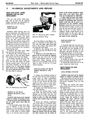
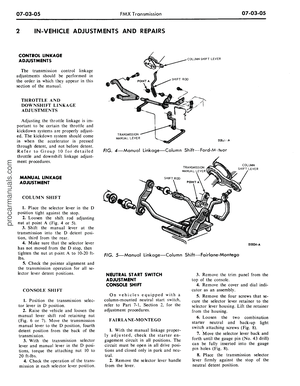
a. To remove the valve spool, hold
the valve assembly in both hands with
the stub shaft pointing downward.
Push lightly on the valve spool with a
small rod by inserting the rod through
the openings in the end cap (Fig. 18)
until the spool is far enough out of the
valve so that it may be grasped by the
hand. Withdraw the spool with a
steady oscillating pull to prevent jam-
ming. If slight sticking occurs, make a
gentle attempt to reverse the with-
drawal procedure. If this does not free
the spool, it has become cocked in the
valve body bore. Do not attempt to
force the spool in or out if it becomes
cocked. In this case, continue to disas-
semble the valve assembly as follows
and return to the spool as described
later. Remove the stub shaft, torsion
bar, and end cap assembly by holding
the thumbs on the valve body as
shown in Fig. 18. Tap the torsion bar
lightly against the workbench. This
will dislodge the cap from the valve
body to cap pin. The stub shaft, tor-
sion bar and end cap assembly can
now be removed from the valve body.
b.
If the valve spool has become
cocked as described in step 3 above, it
can now be freed. By visual inspection
on a flat surface it can be determined
in which direction the spool is cocked.
A few very light taps with a light soft
plastic or raw-hide mallet should align
the spool in the bore and free it. Do
not tap with anything metallic. If
spool can be rotated, it can be re-
moved.
4.
Remove O-ring dampener seal
from the spool and discard it.
5.
Carefully cut the valve rings and
the ring back-up seals, remove and
discard them, providing the rings show
evidence of excessive wear. The valve
rings are made of filled teflon and it is
very unusual that replacement is re-
quired.
6. Remove the dampener O-ring
from the valve spool and discard it.procarmanuals.com
Page 159 of 413

03-09-07
Saginaw Design Integral Power Steering Gear
03-09-07
VALVE SPOOL
DAMP EN
ERO-RING
TORSION BAR
G 1633-A
FIG. 18 —Removing Spool
from Valve Body
7.
Dip three new valve body O-
rings and teflon rings in C1AZ-
19582-A lubricant. Install the O-rings
on the valve body being careful not to
twist them. Slide the three teflon rings
into place over the O-rings being care-
ful not to stretch them any more than
necessary.
8. Lubricate a new dampener O-
ring and install it in the spool groove.
9. Assemble the stub shaft in the
valve body making sure that the
groove in the cap engages the pin in
the body. Tap the cap lightly with a
soft-faced hammer to seat it in the
valve body.
10.
Dip the valve spool in C1AZ-
19582-A. With the notch of the spool
toward the valve body, carefully slide
the spooi over the shaft and into the
body rotating it slightly to permit easy
entry. Make sure that the dampener
O-ring is distributed evenly to prevent
TEFLON RING
damage. Guide the spool to engage
the notch with the dowel in the body.
11.
Place the spool spring on the
stub shaft with the larger diameter
toward the spool. Work the small end
of the spring down over the shaft until
the small end is seated in the groove
of the stub shaft.
12.
If, during the assembly of the
valve, the stub shaft and end cap as-
sembly is allowed to slip out of en-
gagement with the valve body pin, the
spool will be permitted to enter the
valve body too far. The dampener O-
ring seal will expand into the valve
body fluid grooves preventing with-
drawal of the spool. Attempt to with-
draw the spool with a slight pull and
much rotary motion. If this does not
free the spool after several tries, make
sure that the spool is free to rotate;
place the valve body on a flat surface
with the notched end up, and tap the
spool with a wooden or plastic rod
until the O-ring seal is cut and the
spool can be removed. Replace the
dampener O-ring seal and proceed
with the assembly procedure as be-
fore.
RACK-PISTON
1.
Cut the teflon ring and the O-
ring from the piston.
2.
Place the assembly on a clean
lint-free cloth and remove the screws
that attach the ball return guide clamp
to the rack piston and remove the
clamp (Fig. 19).
3.
Lift the ball return guides from
the rack-piston.
4.
Remove Tool T65P-3D517-A
from the piston and remove the re-
maining balls.
5.
Thoroughly clean all parts.
END PLUG
RACK PI STON
DARK COLORED BALLS
(11 REQUIRED)
V
0-RING
POLISHED BALLS
(II REQUIRED)
BALL RETURN GUIDE
CLAMP
B
G1296. A
6. Lubricate a new O-ring and tef-
lon ring. Install the O-ring on the pis-
ton being qareful not to twist it. Slide
the teflon ring into place being careful
not to stretch it any more than neces-
sary.
7.
Slide worm (Fig. 20) fully into
the rack-piston. Load 16 balls into the
guide hole nearest the teflon ring
while slowly rotating the worm count-
erclockwise to feed the balls through
circuit. Alternate the dark colored
balls with the polished balls through
the circuit.
TEFLON RING
FIG. 19—Rack-Piston Disassembled
G 1632-A
FIG. 20—Assembling Rack Piston
Apply Lubriplate liberally to one of
the ball return guides and install the
six remaining balls in the guide. Place
the other half of the guide in position
and insert them into holes in the
rack-piston. Be sure that the dark ball
in the guide is installed next to the
polished ball in the rack-piston. Install
the ball return guide clamp with
screws and lock washers. Tighten the
screws to 8-12 ft-lbs.
8. The worm groove is ground with
a high point in the center. V/hen the
rack-piston passes over this high point
there should be a preload of 1-4 in-
lbs.
Clamp the rack-piston in a vise
with soft jaws with the worm shaft
pointing up. To avoid distortion, do
not tighten the vise too tight.
9. Place the valve assembly on the
worm, engaging the worm drive pins.
Rotate the worm until it extends 1
1/4 inch from the rack-piston to the
thrust bearing face. This is the center
position.
10.
Place an in-lb torque wrench
with a 3/4-inch-deep wall 12-point
socket on the stub shaft, and rotate
the wrench through an arc of approxi-
mately 60 degrees in both directions
several times, then take a torque read-
ing. The highest average reading ob-
tained with the worm rotating should
be between 1-4 in-lbs.
11.
If this reading is too high or
too low a new set of balls should beprocarmanuals.com
Page 160 of 413

03-09-08
Saginaw Design Integral Power Steering Gear
03-09-08
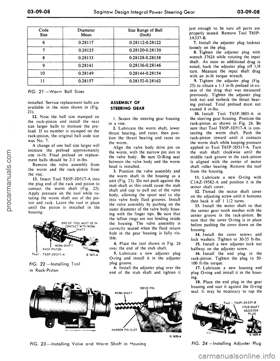
Code
Size
6
7
8
9
10
11
Diameter
Mean
0.28117
0.28125
0.28133
0.28141
0.28149
0.28157
Size Range of Ball
(Inch)
0.28112-0.28122
0.28120-0.28130
0.28128-0.28138
0.28136-0.28146
0.28144-0.28154
0.28152-0.28162
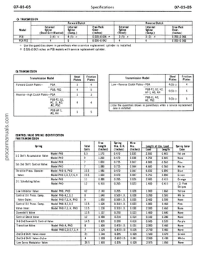
FIG. 21 —Worm Ball Sizes
installed. Service replacement balls are
available in the sizes shown in (Fig.
21).
12.
Note the ball size stamped on
the rack-piston and install the next
size larger balls to increase the pre-
load. If no number is stamped on the
rack-piston, the original ball code size
was No. 7.
A change of one ball size larger will
increase the preload approximately
one in-lb. Final preload on replace-
ment balls should be 2-3 in-lbs.
Remove the valve assembly from
the worm and the rack-piston from
the vise.
13.
Insert Tool T65P-3D517-A into
the plug end of the rack and piston to
contact the worm shaft (Fig. 22).
Apply pressure on the tool while ro-
tating the worm shaft out of the pis-
ton and rack. Leave the tool in place
until the piston is installed in the
housing.
END OF TOOL MUST BE IN
CONTACT WITH WORM
SHAFT
Tool * T65P-3D517-A
FIG. 22—Installing Tool
in Raek-Piston
G 1631-A
ASSEMBLY OF
STEERING GEAR
1.
Secure the steering gear housing
in a vise.
2.
Lubricate the worm shaft, lower
thrust bearing, and races; then posi-
tion the thrust bearing and races on
the worm.
Align the valve body drive pin on
the worm, with the narrow pin slot in
the valve body. Be sure O-Ring seal
between the valve body and the worm
head is installed.
3.
Position the valve assembly and
the worm shaft in the housing as a
unit (Fig. 23). Do not push against the
stub shaft as this could cause the stub
shaft and cap to pull out of the valve
body, allowing the spool seal to slip
into valve body fluid grooves. Install
the valve assembly by pushing on the
outer diameter of the valve body hous-
ing with the finger tips. Be sure that
the teflon rings are not binding inside
the housing. The valve assembly is
correctly seated when the fluid return
hole in the gear housing is fully vis-
ible.
4.
Place the tool shown in Fig. 24
over the end of the stub shaft.
5.
Lubricate a new adjuster plug
O-ring and install it in the adjuster
plug groove.
6. Install the adjuster plug over the
end of the stub shaft and tighten it
DRIVE PIN
just enough to be sure all parts are
properly seated. Remove Tool T65P-
3A537-B.
7.
Install the adjuster plug locknut
loosely on the plug.
8. Tighten the adjuster plug with
wrench J7624 while rotating the input
shaft. As soon as additional drag is
noted, back the adjuster plug off 1/8
turn. Measure the input shaft drag
with an in-lb torque wrench.
9. Tighten the adjuster plug (Fig.
25) to obtain a 1-3 in-lb preload in ex-
cess of the drag that was measured
previously. Tighten the adjuster plug
lock nut and recheck the thrust bear-
ing preload. Total preload must not
exceed 8 in-lbs.
10.
Install Tool T65P-3805-A in
the steering gear housing. Position the
rack-piston as shown in Fig. 26. Be
sure that Tool T65P-3D517-A is con-
tacting the worm shaft. Push the
rack-piston inward until it contacts
the worm shaft while keeping pressure
applied to Tool T65P-3D517-A. Turn
the stub shaft clockwise until the
middle rack groove in the rack-piston
is aligned with the center of sector
shaft roller bearing. Remove the tool
from the housing.
11.
Lubricate a new O-ring with
C1AZ-19582-A and position it in the
sector shaft cover.
12.
Thread the sector shaft cover
on the adjusting screw until it bottoms
then back it off 1 1/2 turns.
13.
Install the sector shaft so that
the center gear tooth meshes with the
center groove in the rack-piston. Be
sure that the cover O-ring is in place
before pushing the cover down on the
housing.
14.
Install the cover screws and
lock washers. Tighten to 30-35 ft-lbs.
15.
Install a new adjuster lock nut
halfway on the adjuster screw.
16.
Install the end plug in the
rack-piston. Tighten the plug to 50-
100 ft-lbs torque.
17.
Lubricate a new housing end
plug O-ring and install it in the hous-
ing.
18.
Place the end plug in the gear
housing and seat it against the O-ring
seal. It may be necessary to tap the
Tool
T65P-3A537-B
STUB SHAFT
ADJUSTER
PLUG
G 1630-A
FIG. 23—Installing Valve and Worm Shaft in Housing
G 1629-A
FIG. 24 —Installing Adjuster Plugprocarmanuals.com