Page 273 of 413

06-02-04
Ford Design Three Speed Transmission
06-02-04
shift selector, remove
the
shift selector
assembly from
the
extension housing.
6.
On
Ford, Mercury
and
Meteor
vehicles disconnect
the
parking brake
cable from the equalizer lever and sep-
arate
the
lever from
the
crossmember.
7.
On
Ford, Mercury
and
Meteor
models, remove
the
bolts that secure
the extension housing
to the
engine
rear support.
8. Raise
the
rear
of
the engine high
enough
to
remove
the
weight from
the
crossmember.
9. Support
the
transmission with
a
transmission jack
and
remove
the
transmission from
the
flvwheel hous-
ing.
10.
Move
the
transmission and jack
rearward until
the
input shaft
is
clear
of
the
flywheel housing.
11.
Remove
the
transmission from
the jack
and
mount
it in a
holding
fixture.
Do
not
depress
the
clutch pedal
while
the
transmission
is
removed.
INSTALLATION
1.
Make certain that
the
machined
surfaces
of the
transmission case
and
the flywheel housing
are
free
of
dirt,
paint,
and
burrs.
2.
Install
a
guide
pin in
each lower
mounting bolt hole.
3.
Start
the
input shaft through
the
release bearing. Align
the
splines
on
the input shaft with
the
splines
in the
clutch disc. Move
the
transmission
forward
on the
guide pins until
the
input shaft pilot enters
the
bearing
or
bushing
in the
crankshaft.
If the
transmission front bearing retainer
binds
up on the
clutch release bearing
hub,
work
the
release bearing lever
until
the hub
slides onto
the
transmis-
sion front bearing retainer. Install
the
two transmission-to-flywheel housing
upper mounting bolts
and
lockwash-
ers.
Remove
the two
guide pins
and
install
the
lower mounting bolts
and
lock washers.
4.
Raise
the
rear
of the
engine high
enough
to
provide clearance
for in-
stalling
the
crossmember. Bolt
the
crossmember assembly
to the
frame
side supports.
5.
On
Ford, Mercury
and
Meteor
models, lower
the
engine until
the ex-
tension housing just contacts
the
rear
support. Align
the
bolt holes
in the
extension housing with those
in the
support. Then lower
the
engine
and
remove the jack. Install the two exten-
sion housing-to-support attaching
bolts
and
lock washers.
6.
On
Ford, Mercury
and
Meteor
models, insert
the
parking brake front
cable
in the
equalizer
and
install
the
equalizer
in the
bracket
on the
crossmember. Secure
the
parking
brake rear cable
to the
equalizer.
7.
On
vehicles equipped with
a
column-mounted gear shift selector,
secure
the
shift rods
to the
shift levers
at
the
transmission.
On
vehicles
equipped with
a
floor-mounted gear
shift selector, attach
the
shift selector
assembly
to the
extension housing.
8. Insert
the
speedometer cable
and
driven gear
in the
extension housing
and secure
it
with
a cap
screw
and
lock washer.
9. Remove
the
tool shown
in
Fig.
2,
Part 6-1, from
the
extension housing.
Align
the
reference marks
and
slide
the front universal joint yoke onto
the
output shaft
and
into
the
extension
housing. Connect
the
rear universal
joint
to the
axle pinion flange
and tor-
que
the
nuts
to
specifications.
10.
Fill
the
transmission
to the
proper level with
the
approved lubri-
cant.
11.
Adjust
the
clutch pedal free
travel
and the
shift linkage
as re-
quired.
MAJOR REPAIR OPERATIONS
DISASSEMBLY
1.
Mount
the
transmission
in a
holding fixture and drain
the
lubricant
by removing
the
drain plug,
if so
equipped,
or the
lower extension hous-
ing bolt.
2.
Remove
the cap
screws that
at-
tach
the
cover
to
the case. Remove
the
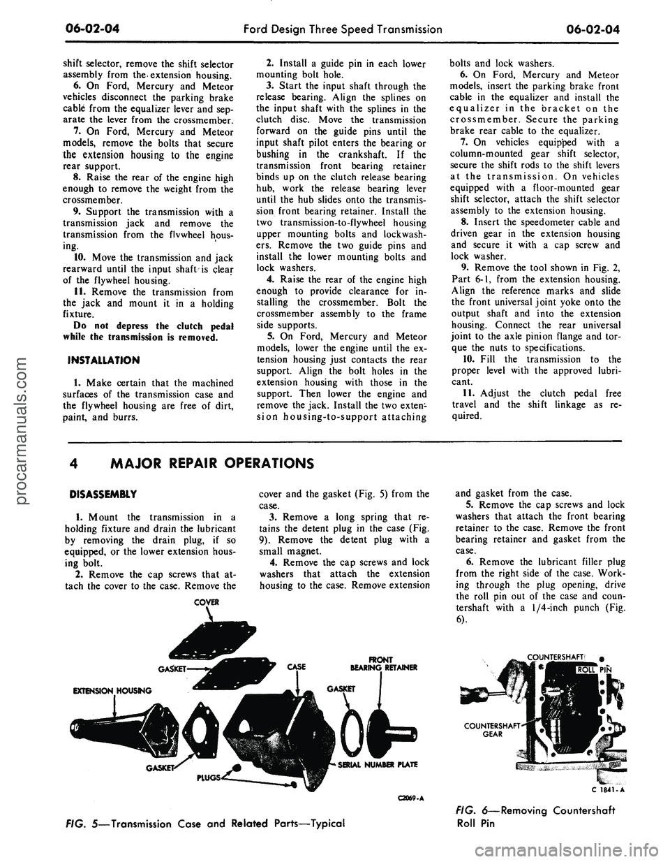
COVER
cover
and the
gasket (Fig.
5)
from
the
case.
3.
Remove
a
long spring that
re-
tains
the
detent plug
in the
case (Fig.
9).
Remove
the
detent plug with
a
small magnet.
4.
Remove
the cap
screws
and
lock
washers that attach
the
extension
housing
to
the case. Remove extension
FRONT
BEARING RETAINER
C2069-A
and gasket from
the
case.
5.
Remove
the cap
screws
and
lock
washers that attach
the
front bearing
retainer
to the
case. Remove
the
front
bearing retainer
and
gasket from
the
case.
6. Remove
the
lubricant filler plug
from
the
right side
of the
case. Work-
ing through
the
plug opening, drive
the roll
pin out of the
case
and
coun-
tershaft with
a
1/4-inch
punch
(Fig.
6).
TERSHAFT'
#
PIN
C 1841-A
FIG. 5—Transmission Case
and
Related Parts—Typical
FIG. 6—Removing Countershaft
Roll
Pinprocarmanuals.com
Page 274 of 413

06-02-05
Ford Design Three Speed Transmission
06-02-05
Dummy
Shaft
FIG. 7—Removing Countershaft
7.
On 6-cylinder vehicles with a
model RAN transmission except
Ford, tap the countershaft from the
rear of the case with a dummy shaft
to remove the expansion plug from
the countershaft bore at the front of
the case.
8. Hold the countershaft gear with
a hook and with the tool shown in
Fig. 7, push the countershaft out the
rear of the case.
The countershaft (cluster) gear and
thrust washers (Fig. 21) can be low-
ered to the bottom of the case. Re-
move the countershaft from the rear
of the case.
9. On some models, remove the
snap ring that secures the speedometer
drive gear on the output shaft. Slide
the speedometer drive gear off the
shaft. Remove the speedometer drive
gear lock ball from the shaft. If the
vehicle is equipped with the new de-
sign retainer, depress the tang on the
speedometer drive gear retaining clip
and slide the gear off the output shaft
(Fig. 10).
10.
Remove the snap ring that re-
tains the output shaft bearing on the
C2070 A
shaft. Remove the bearing from the
case and shaft as shown in Fig. 8.
11.
Place both shift levers in the
neutral (center) position.
12.
Remove the set screw that se-
cures the first and reverse shift fork to
the shift rail. Slide the first and rev-
erse shift rail out through the rear of
the case.
13.
Slide the first and reverse syn-
chronizer forward as far as possible,
and rotate the first and reverse shift
fork upward. Then lift it from the
case.
14.
Move the second and third-
speed shift fork to the second-speed
position to gain access to the set
screw. Remove the set screw from the
fork. Rotate the shift rail 90 degrees
as shown in Fig. 11.
15.
Lift the interlock plug (Fig. 9)
from the case with a magnet.
16.
Tap on the inner end of the sec-
ond and third-speed shift rail to re-
move the expansion plug (Fig. 9) from
the front of the case. Remove the shift
rail.
17.
Remove the second and third-
speed shift rail detent plug and spring
from the detent bore.
18.
Pull the input gear and shaft
forward until the gear contacts the
case,
and then remove the large snap
ring. It is necessary to move the gear
forward to provide clearance when re-
moving the output shaft assembly
from RAT model transmissions. On
all other models, the input shaft and
gear is removed from the front of the
case at this time.
19.
Rotate the second and third-
speed shift fork upward, and lift it
from the case.
20.
Carefully lift the output shaft
assembly out through the top of the
case.
21.
On an RAT model, work the
input shaft bearing and gear back
through the bore in the case and out
through the top. Remove idler gear
shaft, driving from the front of the
case.
22.
Lift the reverse idler gear and
two thrust washer (Fig. 12) from the
case.
Lift the countershaft gear, thrust
washer, and dummy shaft from the
case.
23.
Remove the snap ring from the
front of the output shaft, and slide the
synchronizer and the second-speed
gear (Fig. 13) off the shaft.
24.
Remove the next snap ring and
tabbed thrust washer from the output
shaft. Then slide the first gear and
blocking ring off the shaft.
25.
Remove the next snap ring
from the output shaft. The first and
reverse synchronizer hub is a press fit
on the output shaft. To eliminate the
possibility of damaging the synchro-
nizer assembly, remove the synchro-
nizer hub using an arbor press as
shown in Fig. 21. Do not attempt to
remove or install the hub by hammer-
ing or prying.
C2071-A
FIG. 8—Removing Output Shaft
Bearing
SET SCREW
SCREW
MACHINED SURFACE
2ND AND 3RD SHIFT FORK
EXPANSION PLUG
1ST AND REVERSE
SHIFT RAIL
FIG. 9—Shift Rails and Forks Disassembled
C1798-Aprocarmanuals.com
Page 275 of 413

06-02-06
Ford Design Three Speed Transmission
06-02-06
SPEEDOMETER DRIVE
GEAR
SPRING CLIP
FRONT
C2052-A
FIG. 10—Speedometer Drive Gear Installation—New Design
TOOL-T52T
6500-DJD
C1564-A
FIG. 11—Rotating Second and Third-Speed Shift Rail
PARTS REPAIR
OR
REPLACEMENT
SHIFT LEVERS
AND
SEALS
1.
Remove
the nut,
lock washer,
and flat washer that secure each shift
lever (Fig.
14) to the
lever
and
shaft
in
the transmission case. Lift
the
levers
off
the
shaft. Slide each lever
and
shaft
out of the
case. Discard
the CD-
ring from each shaft.
2.
Lubricate
the new
seals with
transmission lubricant
and
install
them
on the
shafts.
3.
Install
the
lever
and
shafts
in the
case.
4.
Position
a
shift lever
on
each
shaft
and
secure them with
a
flat
washer, lock washer,
and nut.
INPUT SHAFT BEARING
1.
Remove
the
snap ring securing
the input shaft bearing
(Fig. 15), and
press
the
input shaft
out of the
bear-
ing.
2.
Press
the
input shaft bearing
onto
the
input shaft with
the
tool
shown
in Fig. 16, and
install
the
snap
ring
on the
shaft.
SYNCHRONIZERS
1.
Push
the
sychronizer
hub
from
each synchronizer sleeve.
2.
Separate
the
inserts
and
insert
springs from
the
hubs.
Do not mix the
parts from
the
second
and
third-speed
synchronizer with
the
first
and
reverse
synchronizer (Figs.
17 and 18).
3.
Install
the
rear insert spring
in
the groove
of the
first
and
reverse
syn-
SHAFT AND LEVER
0-RING
SHIFT
LEVER
C 1845-A
FIG. 74—Shift Lever and Shafi
Disassembled
REVERSE
IDLER GEAR THRUST
WASHER ROLL
PIN
REVERSE IDLER
GEAR SHAFT
C1799-A
FIG. 72—Reverse Idter Shaft
Disassembled
BLOCKING RING SPEEDOMETER DRIVE GEAR
OUTPUT SHAFT
BLOCKING RINGS
SNAP RING
REAR BEARING
SYNCHRONIZER
THRUST WASHER
REVERSE GEAR
AND SLEEVE
C2072-A
FIG. 13—Output Shaft Disassembledprocarmanuals.com
Page 276 of 413

06-02-07
Ford Design Three Speed Transmission
06-02-07
SNAP RINGS
FIG. 15—Input Shaft Gear Disassembled
C1802-
A
REMOVAL
INSTALLATION
C1O25-B
FIG. 76—Replacing Input Shaft
Bearing
chronizer
hub.
Make sure that
the
spring covers
all
insert grooves. Start
the
hub in the
sleeve making sure that
the alignment marks
are
properly
in-
dexed. Position
the
three inserts
in the
hub making sure that
the
small
end is
over
the
spring
and
that
the
shoulder
is
on the
inside
of the hub.
Slide
the
sleeve
and
reverse gear onto
the hub
until
the
detent
is
engaged. Install
the
front insert spring
in the hub to
hold
the inserts against
the hub. Be
sure
the spring humps
of the
rear spring
cover different inserts than
the
front
spring humps (Fig.
20).
BLOCKING RING
SLEEVE
AND
REVERSE GEAR
C1803-
A
FIG. 17—First
and
Reverse Synchronizer Disassembled
INSERT
HUB AND
SLEEVE ALIGNMENT MARKS
SPRING
BLOCKING m$ERTS
RING
INSERT SPRING
C1804-
A
FIG. 18—Second
and
Third Synchronizer Disassembled
4.
Install
one
insert spring (Fig.
18)
into
a
groove
of the
second
and
third
speed synchronizer
hub,
making sure
that
all
three insert slots
are
fully cov-
ered. With
the
alignment marks
on
the
hub and
sleeve aligned, start
the
hub into
the
sleeve. Place
the
three
in-
serts
on top of the
retaining spring
and push
the
assembly together.
In-
stall
the
remaining insert spring
so
that
the
spring ends cover
the
same
slots
as
does
the
other spring.
Do not
stagger
the
springs. Place
a
synchro-
nizer blocking ring
on
each
end of the
synchronizer sleeve.
COUNTERSHAFT GEAR
BEARINGS
1.
Remove
the
dummy shaft, fifty
roller bearings,
and the two
bearing
retainer washers from
the
countershaft
gear (Fig.
21).
2.
Coat
the
bore
in
each
end of the
countershaft gear with grease.
3.
Hold
the
dummy shaft
in the
gear
and
install
the
twenty-live roller
bearings
and a
retainer washer
in
each
end
of the
gear.
4.
Position
the
countershaft gear,
dummy shaft,
and
roller bearings
in
the case.
5.
Place
the
case
in a
vertical posi-
tion. Align
the
gear bore
and the
thrust washers with
the
bores
in the
case
and
install
the
countershaft.
6. Place
the
case
in a
horizontal
position
and
check
the
countershaft
gear
end
play with
a
feeler gauge.
The
end play should
be
within specifica-
tion.
If not
within specification,
re-
place
the
thrust washers.
7.
After establishing
the
correct end
play, install
the
dummy shaft
in the
countershaft gear
and
allow
the
gear
to remain
at the
bottom
of the
case
until
the
output
and
input shafts have
been installed.
GEAR SHIFT LEVER
AND
CONTROL ASSEMBLY
REMOVAL
AND
INSTALLATION—
FLOOR-MOUNTED
1.
Remove
the
four screws attach-
ing
the
lower boot
to the
floor
pan.
2.
Remove
the two
bolts attaching
the gear shift lever
to the
control
as-
sembly.
3.
Remove
the two
piece lock nuts
that connect
the
shift rods
to the con-
trol assembly.
4.
Remove
the
three bolts retaining
the shift control assembly
to the ex-
tension housing. Allow
the
back-up
light switch
to
hang free.procarmanuals.com
Page 277 of 413

06-02-08
Ford Design Three Speed Transmission
06-02-08
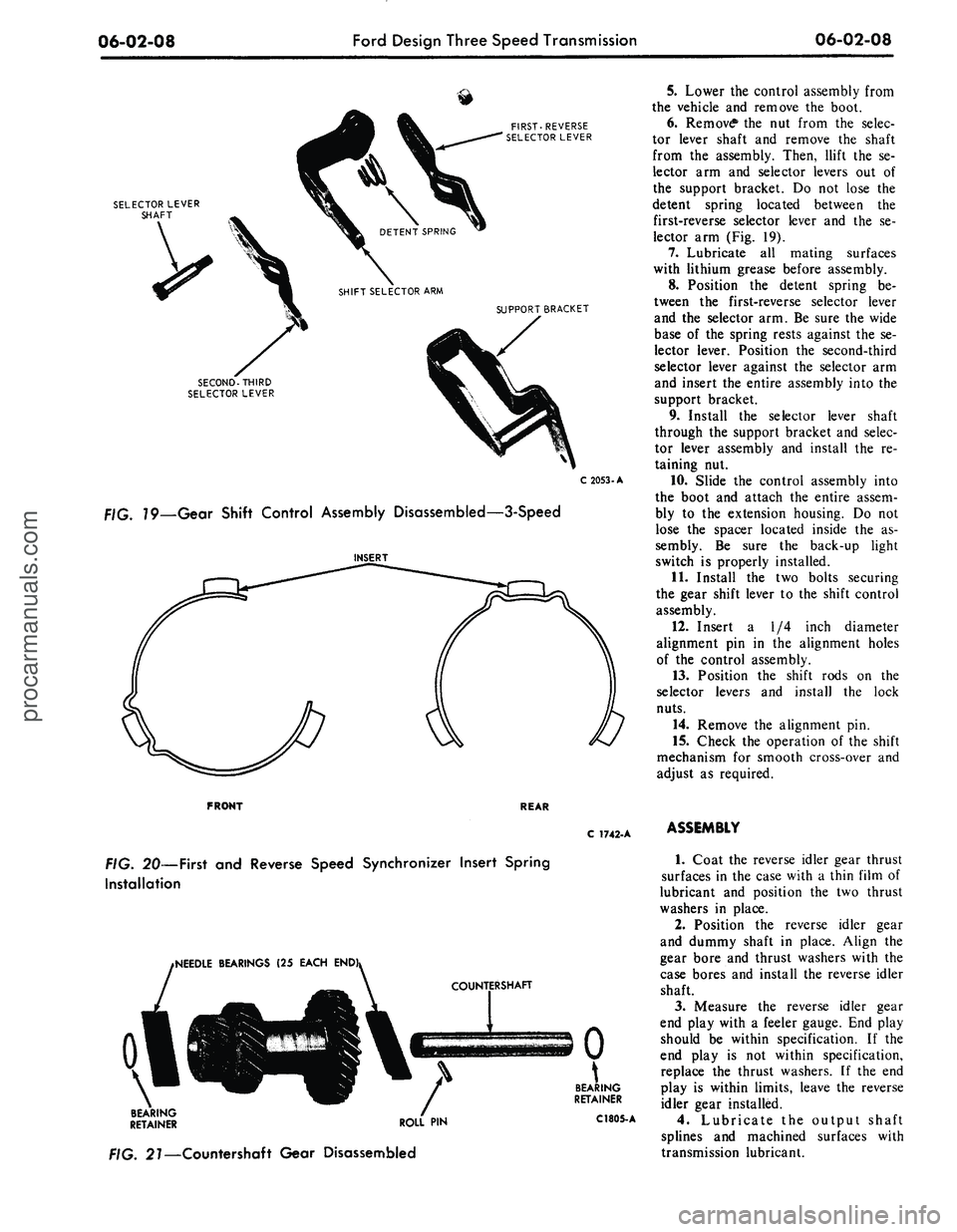
FIRST-REVERSE
SELECTOR LEVER
SELECTOR LEVER
SHAFT
SUPPORT BRACKET
SECOND-THIRD
SELECTOR LEVER
C
2053-A
79—Gear Shift Control Assembly Disassembled—3-Speed
5.
Lower the control assembly from
the vehicle and remove the boot.
6. Remove* the nut from the selec-
tor lever shaft and remove the shaft
from the assembly. Then, llift the se-
lector arm and selector levers out of
the support bracket. Do not lose the
detent spring located between the
first-reverse selector lever and the se-
lector arm (Fig. 19).
7.
Lubricate all mating surfaces
with lithium grease before assembly.
8. Position the detent spring be-
tween the first-reverse selector lever
and the selector arm. Be sure the wide
base of the spring rests against the se-
lector lever. Position the second-third
selector lever against the selector arm
and insert the entire assembly into the
support bracket.
9. Install the selector lever shaft
through the support bracket and selec-
tor lever assembly and install the re-
taining nut.
10.
Slide the control assembly into
the boot and attach the entire assem-
bly to the extension housing. Do not
lose the spacer located inside the as-
sembly. Be sure the back-up light
switch is properly installed.
11.
Install the two bolts securing
the gear shift lever to the shift control
assembly.
12.
Insert a 1/4 inch diameter
alignment pin in the alignment holes
of the control assembly.
13.
Position the shift rods on the
selector levers and install the lock
nuts.
14.
Remove the alignment pin.
15.
Check the operation of the shift
mechanism for smooth cross-over and
adjust as required.
FRONT
REAR
C 1742-A
FIG.
20—First
and
Reverse Speed Synchronizer Insert Spring
Installation
iNEEDLE BEARINGS
(25
EACH
END
\
BEARING
RETAINER ROLL
PIN
. 27—Countershaft Gear Disassembled
BEARING
RETAINER
C1805-
A
ASSEMBLY
1.
Coat the reverse idler gear thrust
surfaces in the case with a thin film of
lubricant and position the two thrust
washers in place.
2.
Position the reverse idler gear
and dummy shaft in place. Align the
gear bore and thrust washers with the
case bores and install the reverse idler
shaft.
3.
Measure the reverse idler gear
end play with a feeler gauge. End play
should be within specification. If the
end play is not within specification,
replace the thrust washers. If the end
play is within limits, leave the reverse
idler gear installed.
4.
Lubricate the output shaft
splines and machined surfaces with
transmission lubricant.procarmanuals.com
Page 278 of 413

06-02-09
Ford Design Three Speed Transmission
06-02-09
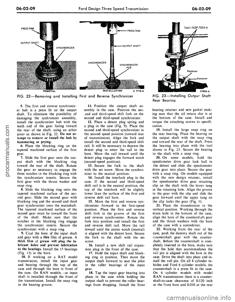
PRESS
RAM
OUTPUT SHAFT
SYNCHRONIZER
PRESS
RAM
OUTPUT SHAFT
Tool-T63P7025-A
SYNCHRONIZER
HUB
REMOVAL INSTALLATION c 1718-A
FIG. 22—Removing
and
Installing First
and
Reverse Synchronizer
5.
The
first
and
reverse synchroniz-
er
hub is a
press
fit on the
output
shaft.
To
eliminate
the
possibility
of
damaging
the
sychronizer assembly,
install
the
synchronizer
hub
with
the
teeth
end of the
gear facing toward
the rear
of the
shaft, using
an
arbor
press
as
shown
in Fig. 22. Do not at-
tempt
to
remove
or
install
the hub by
hammering
or
prying.
6. Place
the
blocking ring
on the
tapered machined surface
of the
first
gear.
7.
Slide
the
first gear onto
the out-
put shaft with
the
blocking ring
toward
the
rear
of the
shaft. Rotate
the gear
as
necessary
to
engage
the
three notches
in the
blocking ring with
the synchronizer inserts. Secure
the
first gear with
the
thrust washer
and
snap ring.
8. Slide
the
blocking ring onto
the
tapered machined surface
of the sec-
ond gear. Slide
the
second gear with
blocking ring
and the
second
and
third
gear synchronizer onto
the
mainshaft.
The tapered machined surface
of the
second gear must
be
toward
the
front
of
the
shaft. Make sure that
the
notches
in the
blocking ring engage
the synchronizer inserts. Secure
the
synchronizer with
a
snap ring.
9. Coat
the
bore
of the
input shaft
and gear with
a
thin film
of
grease.
A
thick film
of
grease will plug
the lu-
bricant holes
and
prevent lubrication
to
the
bearings. Install
the 15
bearings
(Fig.
15) in the
bore.
10.
If
working
on a RAT
model
transmission, install
the
input gear
and bearing through
the top of the
case
and
through
the
bore
in
front
of
the case.
On RAN
models,
me
input
shaft
is
installed through
the
front
of
the transmission. Install
the
snap ring
in
the
bearing groove.
11.
Position
the
output shaft
as-
sembly
in the
case. Position
the sec-
ond
and
third-speed shift fork
on the
second
and
third-speed synchronizer.
12.
Place
a
detent plug spring
and
a plug
in the
case
(Fig. 9).
Place
the
second
and
third-speed synchronizer
in
the second speed position (toward rear
of transmission). Align
the
fork
and
install
the
second
and
third-speed shift
rail.
It
will
be
necessary
to
depress
the
detent plug
to
enter
the
rail
in the
bore.
Move
the
rail inward until
the
detent plug engages
the
forward notch
(second-speed position).
13.
Secure
the
fork
to the
shaft
with
the set
screw. Move
the
synchro-
nizer
to the
neutral position.
14.
Install
the
interlock plug
in the
case.
If the
second
and
third-speed
shift rail
is in the
neutral position,
the
top
of the
interlock will
be
slightly
lower than
the
surface
of the
first
and
reverse shift rail bore.
15.
Move
the
first
and
reverse
syn-
chronizer forward
to the
first-speed
position. Place
the
first
and
reverse
shift fork
in the
groove
of the
first
and reverse synchronizer. Rotate
the
fork into position
and
install
the
first
and reverse shift rail. Move
the
rail
inward until
the
center notch (neutral)
is aligned with
the
detent bore. Secure
the fork
to the
shaft with
the set
screw.
16.
Install
a new
shift rail expan-
sion plug
in the
front
of the
case.
17.
Hold
the
input shaft
and
block-
ing ring
in
position. Then move
the
output shaft forward
to
seat
the
pilot
in
the
roller bearings
of the
input
gear.
18.
Tap the
input gear bearing into
place
in the
case while holding
the
output shaft
to
prevent
the
roller bear-
ings from dropping. Install
the
front
C1806-A
FIG. 23—Installing Output Shaft
Rear Bearing
bearing retainer
and new
gasket
mak-
ing sure that
the oil
return slot
is at
the bottom
of the
case. Install
and
torque
the
attaching screws
to
specifi-
cation.
19.
Install
the
large snap ring
on
the rear bearing. Place
the
bearing
on
the output shaft with
the
snap ring
end toward
the
rear
of the
shaft. Press
the bearing into place with
the
tool
shown
in Fig. 23.
Secure
the
bearing
to
the
shaft with
a
snap ring.
20.
On
some models, hold
the
speedometer drive gear lock ball
in
the detent
and
slide
the
speedometer
drive gear into place. Secure
the
gear
with
a
snap ring.
On
models equipped
with
the new
design retainer, install
the speedometer drive gear retaining
clip
on the
shaft with
the
lower tang
in
the
retaining hole. Align
the
groove
in
the
gear with
the
clip
and
slide
the
gear forward until
the
upper tang
on
the clip locks
the
gear
(Fig. 9).
21.
Place
the
transmission
in the
vertical position. Working through
the
drain hole
in the
bottom
of the
case,
align
the
bore
of the
countershaft gear
and
the
thrust washers with
the
bore
of
the
case with
a
screwdriver.
22.
Working from
the
rear
of the
case,
push
the
dummy shaft
out of the
countershaft gear with
the
counter-
shaft. Before
the
countershaft
is com-
pletely inserted
in the
bore, make sure
that
the
hole that accommodates
the
roll
pin is
aligned with
the
hole
in the
case.
Drive
the
shaft into place
and in-
stall
the
roll
pin. On all 8
cylinder
ve-
hicles
and
Ford
6
cylinder models,
the
countershaft
is a
press
fit in the
case.
On
6
cylinder models with model
RAN transmissions there
is a
counter-
shaft-to-case clearance
of
0.020 inch
at
the
front bore
and 0.010 at the
rearprocarmanuals.com
Page 279 of 413

06-02-10
Ford Design Three Speed Transmission
06-02-10
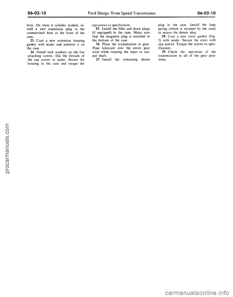
bore.
On these 6 cylinder models, in-
stall a new expansion plug in the
countershaft bore at the front of the
case.
23.
Coat a new extension housing
gasket with sealer and position it on
the case.
24.
Install lock washers on the five
attaching screws. Dip the threads of
the cap screws in sealer. Secure the
housing to the case and torque the
cap screws to specification.
25.
Install the filler and drain plugs
(if equipped) in the case. Make sure
that the magnetic plug is installed in
the bottom of the case.
7.6. Place the transmission in gear.
Pour lubricant over the entire gear
train while rotating the input or out-
put shaft.
27.
Install the remaining detent
plug in the case. Install the long
spring (which is retained by the case)
to secure the detent plug.
28.
Coat a new cover gasket (Fig.
5) with sealer. Secure the cover with
cap screws. Torque the screws to spec-
ification.
29.
Check the operation of the
transmission in all of the gear posi-
tions.procarmanuals.com
Page 280 of 413

06-03-01
Ford Design Four-Speed Transmission
06-03-01
PART
6-3
Ford Design Four Speed
Transmission
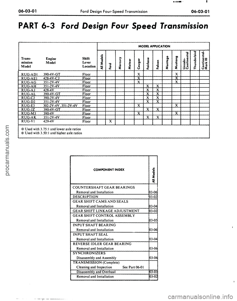
Trans-
mission
Model
RUG-ADI
RUG-AE1
RUG-AG
RUG-AH
RUG-AJ
RUG-AL
RUG-C2
RUG-D2
RUG-E3
RUG-JZ
RUG-M3
RUG-AK
RUG-VI
® Used with
© Used with
Engine
Model
390-4V-GT
428-4V-CJ
351-2V-4V
351-2V-4V
428-4V
390-4V-GT
390-2V-4V
351-2V-4V
302-2V-4V.351-2V-4V
390-4V-GT
390-4V
351-2V-4V
429-4V
3.75:1
and lower axle ratios
3.50:1
and higher axle ratios
Shift
Lever
Location
Floor
Floor
Floor
Floor
Floor
Floor
Floor
Floor
Floor
Floor
Floor
Floor
Floor
MODEL APPLICATION
All
Models
Ford
X
Mercury
Meteor
Cougar
X
X
X
X
X
Fairlane
X
X
X
X
X
X
X
Falcon
X
X
X
X
X
X
X
Montego
Mustang
X
X
X
X
X
Lincoln-
Continental
Thunderbird
Continental-
Mark
III
COMPONENT INDEX
COUNTERSHAFT GEAR BEARINGS
Removal and Installation
DESCRIPTION
GEAR SHIFT CAMS AND SEALS
Removal and Installation
GEAR SHIFT LINKAGE ADJUSTMENT
GEAR SHIFT CONTROL ASSEMBLY
Removal and Installation
INPUT SHAFT BEARING
Removal and Installation
INPUT SHAFTSEAL
Removal and Installation
REVERSE IDLER GEAR BEARING
Removal and Installation
SYNCHRONIZERS
Disassembly and Assembly
TRANSMISSION (Complete)
Cleaning and Inspection
See
Part 06-01
Disassembly and Overhaul
Removal and Installation
All
Models
03-06
03-02
03-04
03-02
03-05
03-06
03-04
03-06
03-06
03-03
03-02
procarmanuals.com