Page 257 of 413

05-02-03
General Clutch Service
05-02-03
in the direction of the face runout
arrow and its center line is parallel to
the center line of the face runout
arrow.
18.
Determine the amount of the
face runout on the B arrow scale.
19.
The value of the circular line
beneath the amount of face runout
will be the desired reading. If the
reading is in excess of 0.014 inch the
housing alignment is unacceptable.
20.
Remove the Dia-L-lgner gauge
from the flywheel housing.
21.
Install the spark plugs and con-
nect the wires.
ENGINE IN VEHICLE
Since any change in face alignment
will change bore alignment, it may be
possible to correct bore alignment by
changing face alignment. Face align-
ment can be changed by shimming be-
tween the flywheel housing and en-
gine.
Fig. 4 shows the type of shim
which can be fabricated.
Not more than 0.010 inch thickness
shims may be used between the fly-
wheel housing and engine. If a 0.010-
inch shim will not bring face and bore
alignment within limits, replace the
flywheel housing.
The shim required is one half the
maximum (—) indicator reading, and
should be located at the point of max-
imum minus (—) indicator reading.
If both the bore and face alignment
are out of limits, shim between the
flywheel housing and engine to bring
face alignment within limits. Check
the bore alignment.
If the bore alignment is out of lim-
its and the face alignment is within
limits,
shim the flywheel housing to
the limit of face misalignment and
check the bore alignment. If it is not
within limits, replace the housing.
ENGINE OUT OF VEHICLE
The same procedure to correct
alignment may be used with the en-
gine out of the vehicle or in the vehi-
cle,
up to the point of replacing the
flywheel housing. If the bore align-
ment cannot be brought within limits
by shimming, follow this procedure:
dure:
1.
Remove the flywheel housing
from the engine and remove the dowel
pins.
Install the flywheel housing and
tighten the attaching bolts.
2.
Install the dial indicator (Fig. 1).
Check the face alignment, and shim as
C2068-A
. 3—Dia-L-lgner Gauge Installed
required to bring face alignment with-
in limits.
3.
Position the indicator to check
the bore alignment. If the bore align-
ment is not within limits, reduce the
tension on the flywheel housing at-
taching bolts so that the housing can
be moved by striking it with a lead
hammer or a block of wood and a
steel hammer.
4.
The lateral alignment should be
brought within limits so that an indi-
cator reading is within limits between
the 9 o'clock and the 3 o'clock posi-
tions on the bore circle. When the lat-
eral alignment is within limits the
housing usually can be moved straight
up or down without disturbing the lat-
eral alignment. When alignment is
within limits, torque the housing bolts
and recheck bore alignment.
5.
If the flywheel housing cannot be
moved enough to bring the alignment
within limits, mark the holes restrict-
ing movement, and then remove the
housing and drill the marked bolt
holes 1/32 inch larger.
6. When the flywheel housing bore
alignment is within limits and the at-
taching bolts are at normal torque,
C 178 4-A
FIG. 4— Fabricated Flywheel
Housing Shim
hand ream the dowel pin holes 1/32
inch larger. Use a straight reamer and
ream from the flywheel housing side.
Oversize dowel pins can be made from
drill rod stock.
7.
Remove the flywheel housing
and then install the oversize dowel
pins in the cylinder block. Complete
the assembly in the usual way.
8. Recheck the flywheel housing
with the Dia-L-lgner gauge to make
sure that the housing is within the spe-
cified limits.procarmanuals.com
Page 258 of 413

05-02-04
General Clutch Service
05-02-04
CLEANING AND INSPECTION
RELEASE BEARING
Wipe all oil and dirt off the release
bearing. The bearing is prelubricated
and should not be cleaned with sol-
vent.
Inspect the bearing retainer for
loose spring clips and rivets.
Inspect the release bearing assembly
for burrs which may cause the assem-
bly to drag on the transmission bear-
ing retainer. Any such burrs should be
cleaned up with fine crocus cloth. If
burrs are found, inspect the transmis-
sion input shaft bearing retainer for
evidence of scoring. Any scoring
should be polished out with crocus
cloth. Coat the bearing retainer with a
thin film of lithium-base grease
(C3VY-19586-A). Prior to release
bearing installation, apply a light film
of lithium base grease (C3VY-
19586-A) on both sides of the release
lever fork where it contacts the release
bearing hub and retaining springs.
Apply a light film of lithium base
grease (C3VY-19586-A) plate to the
release bearing surface that contacts
the pressure plate fingers. Carefully
fill the grease groove inside the bear-
ing hub with lithium base grease (no
polyethylene). Clean all excess grease
from the bore of the bearing hub. Ex-
cess grease will be forced onto the
spline by the transmission input shaft
bearing retainer and will contaminate
the clutch disc. Also, care must be
exercised when applying lubricants to
the release bearing, release bearing
hub and the release lever fork to avoid
excessive grease from contaminating
the clutch disc.
Hold the bearing inner race and ro-
tate the outer race while applying
pressure to it. If the bearing rotation
is rough or noisy, replace the bearing.
Most release bearing failures are
caused by improper clutch pedal ad-
justments. If the clutch linkage does
not have enough free travel, the re-
lease bearing will constantly touch the
release fingers and will spin whenever
the engine is running.
When installing a release bearing on
vehicles equipped with separate hub
and bearing, use the tool shown in
Fig. 5.
Release bearing failure can be
caused by the release lever contact
points being out of plane. Check the
wear on the release bearing assembly
where the release lever contacts it.
If one side of the assembly shows
more wear than the other, the release
lever is bent out of plane, or is not
centering on the bracket on the fly-
wheel housing.
Misalignment between the engine
and transmission can cause release
bearing failure. Other symptoms of
misalignment are transmission jump-
ing out of gear, especially third gear,
drive line vibration; excessive wear in
the pilot bushing, excessive clutch disc
spin time resulting in gear clash, and
excessive transmission gear wear.
PRESSURE PLATE AND COVER
Inspect the surface of the pressure
plate for burn marks, scores, or rid-
ges.
Generally, pressure plate resur-
facing is not recommended. However
minor burn marks, scores, or ridges
may be removed. During the resurfac-
ing process, the flatness of the pres-
sure plate must be maintained. If the
pressure plate is badly heat-checked or
deeply scored, replace the pressure
plate and cover assembly. Clean pres-
sure plate and flywheel surfaces with a
suitable solvent, such as alcohol to be
sure the surfaces are free from any oil
film. Do not use cleaners with petrole-
um base, and do not immerse the
pressure plate in the solvent.
Place the plate on the floor, being
careful not to score or scratch the sur-
face.
Force each individual finger
down, then release quickly. If the fin-
ger does not return quickly, a binding
condition is indicated, and the pres-
sure plate should be replaced.
The pressure plate should be lubri-
cated with a lithium-base grease be-
tween the driving lugs and the edges
of the pressure plate openings, as
shown in Fig. 6. Depress the pressure
plate fingers fully, apply the lubricant,
and then move the fingers up and
down until the lubricant is worked in.
Do not apply excessive lubricant.
CLUTCH DISC
Inspect the clutch disc facings for
oil or grease. Eliminate the source of
any oil or grease before replacing the
disc. An excessive amount of grease in
the pilot bushing or release bearing
hub will find its way to the disc fac-
ings.
Too much lubricant in the trans-
mission or a plugged transmission
vent will force the transmission lubri-
cant out the input shaft and onto the
disc facings. Also, rear main bearing
oil seal leaks or oil leaks from the fly-
wheel mounting bolts can contaminate
the clutch disc.
Inspect the clutch disc for worn or
loose facings. Check the disc for worn
or loose facings. Check the disc for
distortion and for loose rivets at the
hub.
Check for broken springs.
Springs loose enough to rattle will not
cause noise when the car is operating.
Replace the disc assembly if any of
these defects are present. Be especially
careful when installing a new disc to
avoid dropping it or contaminating it
with oil or grease.
PILOT BUSHING
Check the fit of the clutch pilot
bushing in the bore of the crankshaft.
The bushing is pressed into the
crankshaft and should not be loose.
Inspect the inner surface of the bush-
ing for wear or a bell-mouthed condi-
tion. If the bushing is worn or dam-
aged, replace the bushing with a new
service bearing. Refer to the applica-
ble engine for the replacement proce-
dure.
C 1785-A
FIG. 5—Installing Clutch Release
Bearing on Hub
PRESSURE PLATE
AND COVER
DRIVING
LUG
FLYWHEEL
C2048-A
FIG. 6—Pressure Plate Lubrication
Pointsprocarmanuals.com
Page 259 of 413

05-03-01
Clutch
05-03-01
PART 5-3 Clutch
COMPONENT INDEX
CLUTCH EQUALIZER BAR AND/OR
BUSHING
Removal and Installation
CLUTCH PEDAL ASSIST SPRING
Removal and Installation
CLUTCH PEDAL AND/OR BUSHING
Removal and Installation
CLUTCH PEDAL, PEDAL ASSIST SPRING
AND/OR BUSHING
Removal and Installation
CLUTCH PEDAL FREE PLAY ADJUSTMENT
CLUTCH REMOVAL AND INSTALLATION
DESCRIPTION
MODEL APPLICATION
All
Models
Ford
03-05
N/A
N/A
03-03
03-03
03-05
03-01
Mercury
03-05
N/A
N/A
03-03
03-03
03-05
03-01
Meteor
03-05
N/A
N/A
03-03
03-03
03-05
03-01
Cougar
03-05
N/A
N/A
03-04
03-03
03-05
03-01
Fairlane
03-05
03-03
03-04
N/A
03-03
03-05
03-01
Falcon
03-05
03-03
03-04
N/A
03-03
03-05
03-01
Montego
03-05
03-03
03-04
N/A
03-03
03-05
03-01
Mustang
03-05
N/A
N/A
03-04
03-03
03-05
03-01
Lincoln-
Continental
N/A
N/A
N/A
N/A
N/A
N/A
N/A
Thunderbird
N/A
N/A
N/A
N/A
N/A
N/A
N/A
Continental-
Mark
III
N/A
N/A
N/A
N/A
N/A
N/A
N/A
A page number indicates that the item is for the vehicle listed at the head of the column.
N/A indicates that the item is not applicable to the vehicle listed.
DESCRIPTION
DESCRIPTION
The clutch is of the centrifugal sin-
gle dry disc type and consists of the
clutch disc, pressure plate and the
clutch release bearing.
CLUTCH PEDAL
7519
351538-S
VIEW A
BUSHING-2 REQ'D.
7517
C2055-A
FIG.
1—Clutch
Pedal and Linkage Adjustments —
Ford,
Mercury, Meteor
procarmanuals.com
Page 260 of 413
05-03-02
Clutch
05-03-02
IN-VEHICLE ADJUSTMENTS AND REPAIRS
SPRING-7A600
EQJALIZER ROD-7A516
EQUALIZER BAR-7528
SPRING-7523
FELTWASHER-375475
EQUALIZER
EQUALIZER ROD-7A516
LOCKNUT-34809-S7
RELEASE ROD/
7B543
SNAP RING-7A629
OUTER BRACKET-7507
PIVOT-7A531
RELEASE ROD-7B543
RELEASE ROD-7B543
OUTER EQUALIZER BAR-7528
BUSHING-7526
SPRING-7A632
SNAP RING-7A629
FELT WASHER-375475-S
BUSHING-7543 SPRING-7523
FELT WASHER-358979-S
SPRING-7545
FAIRLANE AND MONTEGO
390 AND 428 ENGINES
FAIRLANE AND MONTEGO
302 AND 351
FIG.
2—Clutch
Pedal and Linkage Adjustment — Fairlane, Montego and Falcon
ASSIST SPRING BRACKET 7535-
ASSIST SPRING 7B572
SPRING
7A632
RELEASE ROD 7B543
390 ENGINE
SAME AS MAIN VIEW
EXCEPT AS SHOWN
351 ENGINE
SAME AS MAIN VIEW
EXCEPT AS SHOWN
C2056-A
FIG.
3—Clutch
Pedal and Linkage Adjustment — Mustang, Cougarprocarmanuals.com
Page 261 of 413

05-03-03
Clutch
05-03-03
CLUTCH PEDAL
ADJUSTMENTS
Adjust
the
clutch pedal free travel
whenever
the
clutch does
not
disen-
gage properly,
or
when
new
clutch
parts
are
installed. Improper adjust-
ment
of the
clutch pedal
is one of the
most frequent causes
of
clutch failure
and
can be a
contributing factor
in
some transmission failures.
FREE TRAVEL
1.
Disconnect
the
clutch return
spring from
the
release lever.
2.
Loosen
the
release lever
rod
locknut
and
adjusting
nut
(Figs.
1, 2
and
3).
3.
Move
the
clutch release lever
rearward until
the
release bearing
lightly contacts
the
clutch pressure
plate release fingers.
4.
Adjust
the rod
length until
the
rod seats
in the
release lever pocket.
5.
Insert
the
specified feeler gauge
between
the
adjusting
nut and the
swivel sleeve. Then tighten
the
adjust-
ing
nut
against
the
gauge finger tight.
6. Tighten
the
locknut against
the
adjusting
nut,
being careful
not to di-
sturb
the
adjustment. Torque
the
lock-
nut
to
specification
and
remove
the
feeler gauge.
7.
Install
the
clutch return spring.
8. Check
the
free travel
at the
pedal
for conformance
to
specification.
Re-
adjust
if
necessary.
9.
As a
final check, measure
the
pedal free travel with
the
transmission
in neutral
and the
engine running
at
about 3000
rpm. If the
pedal free
travel
at
this speed
is not a
minimum
of
1/2
inch, readjust
the
clutch pedal
free travel. Otherwise,
the
release
fin-
gers
may
contact
the
release bearing
continuously, resulting
in
premature
bearing
and
clutch failure. Free travel
must
be
exactly
to
specification.
CLUTCH ASSIST
SPRING REPLACEMENT
(FAIRLANE, FALCON,
MONTEGO)
1.
Remove
the
cotter
pin
from
the
clutch
rod at the
clutch pedal lever
as-
sembly inside
the
passenger compart-
ment.
2.
Grasp
the
clutch pedal lever
firmly
to
prevent slipping
and
remove
the clutch
rod
from
the
lever. Allow
the clutch pedal lever
to
rest
on the
floor panel.
3.
Remove
the
forward bolt secur-
ing
the
assist spring bracket
to the
brake pedal bracket
and
loosen
the
rear bolt
two or
three turns.
Do not
remove
the
rear bolt.
4.
Grasp
the
assist spring bracket
with pliers
and
rotate upward until
the
spring
can be
separated from
the
bracket.
BRAKE PEDAL
BRACKET
CLUTCH ASSIST SPRING
BRACKET
-
7535
CLUTCH PEDAL
7519
5.
Position
the
assist spring
in the
clutch pedal spring bracket
and the
assist spring bracket. Rotate
the
spring bracket downward until
the
forward bolt holes
in the
assist spring
bracket line
up
with
the
holes
in the
brake pedal bracket
(Fig. 4).
6. Install
the
forward bolt retaining
the assist spring bracket
to the
brake
pedal bracket
and
torque
the
forward
and rear bolts
to
specification.
7.
Install
the
clutch
rod to the
clutch pedal lever
and
insert
the
cotter
pin.
CLUTCH PEDAL, PEDAL
ASSIST SPRING AND/OR
BUSHING REMOVAL
AND INSTALLATION
FORD, MERCURY,
METEOR
1.
Remove
the pin
that secures
the
clutch pedal-to-equalizer
rod to the
clutch pedal.
2.
Grasp
the
clutch pecal lever
firmly
to
prevent slipping
and
remove
the clutch
rod
from
the
lever. Allow
the clutch pedal lever
to
rest
on the
floor.
3.
Loosen
the
lower bolt securing
the assist spring bracket
to the
pedal
support bracket
two or
three turns.
Then, remove
the
upper bolt from
the
bracket.
Do not
remove
the
lower
bolt.
4.
Grasp
the
assist spring bracket
with pliers
and
rotate
it
counterclock-
wise until
the
spring
is
free
(Fig 5).
5.
Remove
the
retaining ring from
the
end of the
clutch pedal shaft. Then
remove
the
shaft, bushings
and
clutch
pedal from
the
support.
6. Remove
the
bushings from
the
pedal shaft
and
pedal support
and
transfer
the
rubber pedal
pad.
7.
After lubricating
the
pedal shaft
ASSIST SPRING
LOWER BOLT
ASSIST SPRING BRACKET-
UPPER
BOL"
C 1769-B
FIG. 4—Clutch Pedal Assembly
—
Fairlane, Montego, Falcon
C2058-A
;. 5—Removing Clutch Assist
Spring
—
Ford,
Mercury and Meteorprocarmanuals.com
Page 262 of 413

05-03-04
Clutch
05-03-04
bushings, position the clutch pedal and
bushings in the pedal support.
8. Install the retaining ring on the
clutch pedal shaft.
9. Position the assist spring in the
pedal support bracket and the assist
spring bracket. Rotate the assist
spring bracket clockwise until the
upper bolt holes line up and install the
bolt. Torque both the upper and lower
bolts to specification.
10.
Check the clutch pedal free
travel and adjust as required.
MUSTANG, COUGAR
1.
Disconnect the battery ground
cable.
2.
Remove the steering column.
Refer to Group 3 of this manual for
the procedure.
3.
Remove the two capscrews re-
taining the master cylinder or booster
to the dash panel. Then remove the
two capscrews retaining the pedal sup-
port bracket to the dash panel.
4.
Working inside the vehicle, dis-
connect the clutch pedal-to-equalizer
rod at the clutch pedal by removing
the retainer and bushing.
5.
Secure the clutch pedal against
the bumper stop with a small C-clamp
as shown in Fig. 6.
6. Disconnect the stop light switch
wires at the connector.
7.
Remove the switch retainer and
slide the stop light switch off the
brake pedal pin just far enough for
the switch outer hole to clear the pin.
Then lower the switch away from the
pin.
Remove the master cylinder push
CLUTCH PEDAL ASSIST SPRING
rod, bushing and nylon washer from
the brake pedal pin.
8. Remove the screw retaining the
pedal support bracket to the top inner
cowl bracket (Fig. 6).
9. Remove the two sheet metal
screws retaining the pedal support
bracket to the dash panel.
10.
Remove the two screws retain-
ing the pedal support bracket to the
upper cowl brace and lower the pedal
support bracket away from the steer-
ing column studs.
11.
Remove the pedal support
bracket assembly from the vehicle.
12.
Mount the bracket in a vise.
13.
Remove the small C-clamp se-
curing the clutch pedal to the bumper.
Slowly pivot the pedal away from the
bumper until the assist spring can be
lifted from its seat.
14.
Remove the retainer clip from
the clutch and brake pedal shaft.
Then, remove the clutch pedal and
shaft assembly, brake pedal assembly,
and bushings from the pedal support
bracket.
15.
Apply a coating of SAE 10 en-
gine oil to the bushings and locate all
bushings in their proper places on the
brake and clutch pedal assemblies.
16.
Position the brake pedal to the
pedal support bracket. Install the
clutch and brake pedal shaft through
the pedal support and brake pedal as-
sembly. Install the retainer.
17.
Install the clutch pedal assist
spring and pivot the pedal against its
bumper stop. Secure the pedal against
the bumper with a small C-clamp as
TOP INNER COWL-TO-BRACKET
RETAINING SCREW
C2057-A
FIG.
6—Clutch
Pedal —Mustang and Couga?
shown in Fig. 6.
18.
Position the pedal support
bracket assembly to the dash panel
and to the steering column retainer
studs.
19.
Align the pedal support bracket
holes with the holes in the dash panel
and install the two sheet metal screws.
20.
Install the two capscrews at-
taching the pedal support bracket to
the upper cowl bracket.
21.
Install the screw attaching the
support bracket to the top inner cowl
bracket (Fig. 6).
22.
Install the inner nylon washer,
bushing master cylinder push rod on
the brake pedal pin. Position the stop
light switch so that it straddles the
push rod with the switch slot on the
pedal pin and the switch outer hole
just clearing the pin. Slide the switch
completely onto the pin, and install
the outer nylon washer. Secure with
the self-locking pin.
23.
Connect the stop light switch
wires to the connector and install the
wires to the retaining clip.
24.
Connect the clutch pedal-
to-equalizer rod to the clutch pedal
assembly with the bushing and retain-
er and remove the C-clamp from the
bracket.
25.
Working from the engine side
of the dash panel, install the two cap-
screws attaching the pedal support
bracket to the dash panel. Then install
the two screws attaching the master
cylinder to the dash panel.
26.
Install the steering column.
Refer to Group 3 of this manual for
the procedure.
27.
Adjust the clutch pedal free
travel.
28.
Check the brake pedal free
height and travel measurements
(Group 2).
29.
Connect the battery ground
cable.
CLUTCH PEDAL AND/OR
BUSHING REMOVAL
AND INSTALLATION
MOM EGO, FALCON
FAIRLANF
1.
Remove the retaining clip (Fig.
2) that secures the equalizer rod to the
clutch pedal. Disconnect the rod from
the pedal.
2.
Remove the lower bolt retaining
the assist spring bracket to the pedal
support. Then, loosen the upper
bracket retaining bolt (approximately
4 turns) and disconnect the spring
from the clutch pedal and bracket.
3.
Disconnect the brake pedal push
rod from the brake pedal.procarmanuals.com
Page 263 of 413

05-03-05
Clutch
05-03-05
4.
Remove the bolt that secures the
left air vent control cable bracket to
the instrument panel. Position the
control cable to one side.
5.
Remove the retaining clip and
flat washer from the clutch pedal
shaft. Then, remove the shaft, bush-
ing, clutch pedal and brake pedal
from the support.
6. Remove the bushings from the
pedal shaft, and transfer the pedal
pad.
7.
Lubricate the clutch pedal shaft
bushings and position them on the
shaft. Then, position the brake pedal
and clutch pedal in the pedal support.
8. Install the flat washer and re-
taining clip on the pedal shaft.
9. Position the assist spring to the
pedal and bracket. Pry the bracket
forward and install the lower bolt.
Torque the bolts to specifications.
10.
Position the master cylinder
push rod, bushing, and washers on the
brake pedal and secure with a retain-
ing clip.
11.
Connect the equalizer rod to
the clutch pedal and secure it in place
with a retaining clip.
12.
Position the air vent control
cable bracket to the instrument panel
and secure with the attaching bolt.
13.
Adjust the clutch pedal free
travel.
EQUALIZER BAR AND/OR
BUSHING REMOVAL AND
INSTALLATION
FORD, MERCURY
AND METEOR
1.
Raise the vehicle and disconnect
the clutch pedal-to-equalizer rod at
the equalizer bar (Fig. 1).
2.
Disconnect the return spring and
retaining spring at the release lever.
Separate the release lever rod from
the release lever.
3.
Remove the equalizer bar frame
bracket from the frame.
4.
Remove the equalizer bar from
the pivot on the flywheel housing.
5.
Remove the wire clip to replace
the outer bushing and the snap ring
from the inner pivot stud to replace
the inner bushing.
6. Position the flat washer, felt
washer and bushing on the inner and
outer pivots. Secure these parts with
the snap ring.
7.
Position the equalizer bar on the
inner pivot and bolt the equalizer bar
frame bracket to the frame. Torque
the attaching bolts to specification.
8. Install the clutch release rod, re-
turn spring and retaining spring.
9. Connect the clutch pedal rod to
the equalizer bar.
10.
Adjust the clutch pedal free
travel.
MUSTANG, COUGAR,
MONTEGO, FALCON,
FAIRLANE (EXCEPT
MONTEGO AND FAIRLANE
WITH 390 V-8)
1.
Disconnect the clutch pedal
equalizer rod at the equalizer bar
(Figs.
2 and 3).
2.
Raise the vehicle and disconnect
the release lever, return spring at the
lever.
3.
Remove the equalizer bar outer
bracket and bushing assembly.
4.
Remove the release rod from the
equalizer bar, and then remove the
equalizer bar. Remove the bushing
and washers from the inner mounting
stud.
5.
Position the equalizer bar, wash-
ers,
inner bushing, and retainer on the
inner stud.
6. After positioning the outer bush-
ing, install the outer bracket (with the
equalizer bar in place).
7.
Connect the release rod and the
release lever return spring.
8. Lower the vehicle. Connect the
clutch pedal equalizer rod to the
equalizer baY and secure with the re-
taining pin.
9. Adjust the clutch pedal free trav-
el as required.
MONTEGO AND
FAIRLANE—390 V-8
1.
Disconnect the clutch pedal
equalizer rod at the equalizer bar (Fig.
2).
2.
Raise the vehicle and disconnect
the return spring at the release lever.
Disconnect the release lever rod from
the equalizer lever.
3.
Remove the equalizer bar center
bolt.
4.
Separate the equalizer bar and
remove both sections from the vehicle.
5.
Remove the bolts retaining the
equalizer bar inner bracket to the fly-
wheel housing and remove the bracket
and bushing assembly.
6. Remove the equalizer bar outer
bracket and bushing assembly.
7.
Remove the snap ring, bushing,
and felt washer from each bracket as-
sembly.
8. Position a felt washer, and bush-
ing on each bracket assembly and se-
cure with the snap ring.
9. Install the outer bracket and
bushing assembly to the frame (Fig.
2).
Torque the bracket attaching bolts
to specifications.
10.
Position the outer section of the
equalizer bar on the outer bracket
pivot.
11.
Connect the two sections of the
equalizer bar. Insert the inner bracket
pivot into the equalizer bar and install
the assembly to the flywheel housing.
Torque the attaching bolts to specifi-
cations.
12.
Install the equalizer bar center
bolt and torque to specifications.
Make sure that both ends of the
equalizer bar are against the felt
washers.
13.
Connect the release rod and the
release lever return spring.
14.
Adjust the clutch pedal free
travel.
15.
Lower the vehicle. Connect the
clutch pedal equalizer rod to the
equalizer bar and secure with the re-
taining clip.
16.
Check the free travel at the
pedal for conformance to specifica-
tions.
Readjust if necessary.
REMOVAL AND INSTALLATION
CLUTCH REMOVAL
1.
Raise the vehicle on a hoist.
2.
Disconnect the drive shaft from
the rear U-joint flange. Then, slide the
drive shaft off the transmission output
shaft. Insert the appropriate tool over
the output shaft and into the extension
housing oil seal.
3.
Disconnect the speedometer
cable from the extension housing.
4.
Disconnect the gear shift rods
from the transmission. If the vehicle is
equipped with a four-speed transmis-
sion, remove the bolts that secure the
four-speed transmission, disconnect
the front brake cable from the cross-
member and remove the crossmem-
member from the vehicle.
5.
Remove the bolts that attach the
transmission to the flywheel housing.
6. Move the transmission rearward
until the input shaft clears the fly-
wheel housing, then remove it from
the vehicle.
7.
Disconnect the clutch release
lever retaining spring from the release
lever.procarmanuals.com
Page 264 of 413

05-03-06
Clutch
05-03-06
8. Remove the starter cable then
remove the starter motor from the fly-
wheel housing.
9. Remove the bolts that secure the
engine rear plate to the front lower
part of the flywheel housing.
10.
Remove the flywheel housing
lower cover (390 CID housing only).
11.
Remove the bolts that attach
the housing to the cylinder block.
12.
Move the housing back just far
enough to clear the pressure plate,
then move it to the right to free the
pivot from the clutch equalizer bar. Be
careful not to disturb the linkage and
assist spring.
13.
Loosen the six pressure plate
cover attaching bolts evenly to release
the spring tension. If the same pres-
sure plate and cover is to be installed
after the clutch is overhauled, mark
the cover and flywheel so that the
pressure plate can be installed in the
same position.
14.
Remove the pressure plate and
the clutch disc from the flywheel.
CLUTCH INSTALLATION
1.
Install the clutch release lever if
it was removed.
2.
Place the clutch disc, and pres-
sure plate assembly in position on the
flywheel. Start the cover attaching
bolts to hold the pieces in place, but
do not tighten them. Avoid touching
the clutch disc facing, dropping the
parts or contaminating them with oil
or grease as clutch chatter may result.
3.
Align the clutch disc with the
tool shown in Fig. 7, and alternately
tighten the bolts a few turns at a time
until they are all tight. Then torque
the six pressure plate cover attaching
bolts to specification before removing
the tool.
4.
Apply a light film of grease
(C3VY-19586-A) to the outside diam-
eter of the transmission front bearing
retainer. Apply a light film of grease
(C3VY-19586-A) to both sides of the
release lever fork where it contacts the
release bearing bore spring clips.
Apply a light film of grease to the re-
lease bearing surface that contacts the
pressure plate release fingers. Fill the
grease groove of the release bearing
hub with lithium base grease (C3VY-
19586-A). Clean all excess grease
from inside the bore of bearing hub.
Excess grease will be forced onto the
spline by the transmission input shaft
bearing retainer and will contaminate
the clutch disc. Also, place the release
bearing and hub on the release lever.
5.
Make certain that the flywheel
housing and the cylinder block mount-
ing surfaces are clean. Position the
felt washer on the pivot in the fly-
wheel housing. Slip the pivot into the
clutch equalizer shaft being careful
not to disturb the linkage and at the
same time position the housing on the
dowels in the cylinder block. Install
and torque the attaching bolts to spec-
ification.
6. Install the starting motor and
connect the cable.
7.
The mounting surfaces of the
transmission and the flywheel housing
must be free of dirt, paint, and burrs.
Install two guide pins in the flywheel
housing lower mounting bolt holes.
Move the transmission forward on the
guide pins until it is tightly positioned
against the flywheel housing.
8. Install the two upper mounting
bolts.
Then, remove the guide pins
and install the two lower mounting
bolts.
Torque all the bolts to specifica-
tion.
9. Raise the rear of the engine and
install the crossmember. Install and
torque the crossmember attaching
bolts to specifications, then lower the
engine.
10.
Install the extension housing-
to-engine rear support attaching bolts.
Torque the bolts to specification.
11.
Remove the transmission jack
and connect the parking brake cable.
12.
If the vehicle is equipped with a
four-speed transmission, connect the
gear shift linkage control bracket to
the extension housing.
13.
Connect the gear shift rods to
the transmission. Adjust the shift link-
age as required.
14.
Connect the release lever retain-
ing spring. Install the flywheel housing
cover (390 CID housing only).
15.
Remove the tool from the
transmission output shaft and install
the drive shaft.
16.
Check the clutch pedal free
travel.
CLUTCH ARBOR CLUTCH DISC
PRESSURE PLATE
C 1788-A
FIG. 7—Installing Clutch Disc —
Typicalprocarmanuals.com
 1
1 2
2 3
3 4
4 5
5 6
6 7
7 8
8 9
9 10
10 11
11 12
12 13
13 14
14 15
15 16
16 17
17 18
18 19
19 20
20 21
21 22
22 23
23 24
24 25
25 26
26 27
27 28
28 29
29 30
30 31
31 32
32 33
33 34
34 35
35 36
36 37
37 38
38 39
39 40
40 41
41 42
42 43
43 44
44 45
45 46
46 47
47 48
48 49
49 50
50 51
51 52
52 53
53 54
54 55
55 56
56 57
57 58
58 59
59 60
60 61
61 62
62 63
63 64
64 65
65 66
66 67
67 68
68 69
69 70
70 71
71 72
72 73
73 74
74 75
75 76
76 77
77 78
78 79
79 80
80 81
81 82
82 83
83 84
84 85
85 86
86 87
87 88
88 89
89 90
90 91
91 92
92 93
93 94
94 95
95 96
96 97
97 98
98 99
99 100
100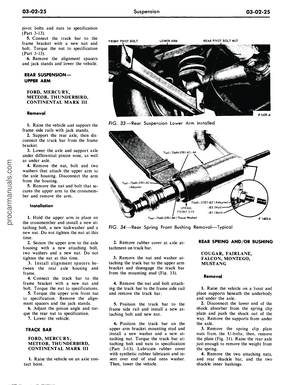 101
101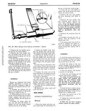 102
102 103
103 104
104 105
105 106
106 107
107 108
108 109
109 110
110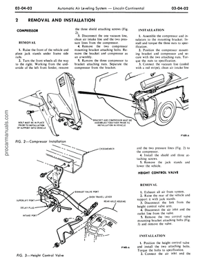 111
111 112
112 113
113 114
114 115
115 116
116 117
117 118
118 119
119 120
120 121
121 122
122 123
123 124
124 125
125 126
126 127
127 128
128 129
129 130
130 131
131 132
132 133
133 134
134 135
135 136
136 137
137 138
138 139
139 140
140 141
141 142
142 143
143 144
144 145
145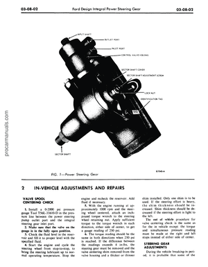 146
146 147
147 148
148 149
149 150
150 151
151 152
152 153
153 154
154 155
155 156
156 157
157 158
158 159
159 160
160 161
161 162
162 163
163 164
164 165
165 166
166 167
167 168
168 169
169 170
170 171
171 172
172 173
173 174
174 175
175 176
176 177
177 178
178 179
179 180
180 181
181 182
182 183
183 184
184 185
185 186
186 187
187 188
188 189
189 190
190 191
191 192
192 193
193 194
194 195
195 196
196 197
197 198
198 199
199 200
200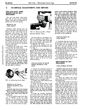 201
201 202
202 203
203 204
204 205
205 206
206 207
207 208
208 209
209 210
210 211
211 212
212 213
213 214
214 215
215 216
216 217
217 218
218 219
219 220
220 221
221 222
222 223
223 224
224 225
225 226
226 227
227 228
228 229
229 230
230 231
231 232
232 233
233 234
234 235
235 236
236 237
237 238
238 239
239 240
240 241
241 242
242 243
243 244
244 245
245 246
246 247
247 248
248 249
249 250
250 251
251 252
252 253
253 254
254 255
255 256
256 257
257 258
258 259
259 260
260 261
261 262
262 263
263 264
264 265
265 266
266 267
267 268
268 269
269 270
270 271
271 272
272 273
273 274
274 275
275 276
276 277
277 278
278 279
279 280
280 281
281 282
282 283
283 284
284 285
285 286
286 287
287 288
288 289
289 290
290 291
291 292
292 293
293 294
294 295
295 296
296 297
297 298
298 299
299 300
300 301
301 302
302 303
303 304
304 305
305 306
306 307
307 308
308 309
309 310
310 311
311 312
312 313
313 314
314 315
315 316
316 317
317 318
318 319
319 320
320 321
321 322
322 323
323 324
324 325
325 326
326 327
327 328
328 329
329 330
330 331
331 332
332 333
333 334
334 335
335 336
336 337
337 338
338 339
339 340
340 341
341 342
342 343
343 344
344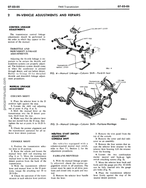 345
345 346
346 347
347 348
348 349
349 350
350 351
351 352
352 353
353 354
354 355
355 356
356 357
357 358
358 359
359 360
360 361
361 362
362 363
363 364
364 365
365 366
366 367
367 368
368 369
369 370
370 371
371 372
372 373
373 374
374 375
375 376
376 377
377 378
378 379
379 380
380 381
381 382
382 383
383 384
384 385
385 386
386 387
387 388
388 389
389 390
390 391
391 392
392 393
393 394
394 395
395 396
396 397
397 398
398 399
399 400
400 401
401 402
402 403
403 404
404 405
405 406
406 407
407 408
408 409
409 410
410 411
411 412
412