Page 57 of 413

02-02-38
Brake System
02-02-38
2.
Disconnect the actuator solenoid
and warning switch harness connectors
from the control module.
3.
Remove the two wiring harness
grommets from the dash panel and
push the wiring harness and connec-
tors through the openings in the dash
panel.
4.
Working in the engine compart-
ment loosen the hose clamp and re-
move the air hose from the air filter.
5.
Remove the engine air cleaner-
Loosen the hose clamp and remove
the vacuum hose from the vacuum
manifold fitting.
6. Raise the vehicle on a hoist.
7.
Disconnect the exhaust pipes
from the exhaust manifold and sup-
port with wire to provide access to the
actuator assembly.
8. Remove the bolt retaining the
actuator ground wire to the rear outer
corner of the engine right bank.
9. Loosen the tube nuts and discon-
nect the brake system hydraulic tubes
from the hydraulic valve housing.
10.
Remove the three nuts retaining
the actuator assembly to the actuator
support bracket.
11.
Remove the three bolts that re-
tain the actuator mounting bracket to
the side rail and remove the mounting
bracket.
12.
Remove the actuator assembly
from the vehicle and place it on a
bench.
13.
Remove the air and vacuum
hoses from the actuator.
INSTALLATION
1.
Install the air and vacuum hoses
on the new actuator.
2.
Place the actuator assembly into
position under the vehicle, routing the
air and vacuum hoses up between the
engine and fender apron and inserting
the solenoid leads through the holes in
the firewall.
3.
Position the ground wire to the
rear of the engine block and install re-
taining bolt.
4.
Position the actuator mounting
bracket to the frame side rail and in-
stall the three retaining bolts.
5.
Position the actuator assembly
to the mounting bracket and install
the three retaining nuts.
6. Connect the hydraulic tubes to
the hydraulic valve assembly and
tighten the tube nuts to specifications.
7.
Connect the exhaust pipes to the
exhaust manifolds.
8. Lower the vehicle.
9. Pull the actuator solenoid and
brake warning switch wiring harness
through the two holes in the dash
panel from inside the car. Seat the
wiring harness grommets in the dash
panel.
10.
Connect the actuator solenoid
and brake warning switch wiring har-
ness connectors to the control mo-
dules.
'
11.
Position the control module in
the bracket under the glove box and
install the retaining screw.
12.
In the engine compartment con-
nect the air hose to the air filter and
position the hose clamp.
13.
Connect the vacuum hose to the
engine vacuum manifold fitting. In-
stall the engine air cleaner.
14.
Bleed the rear brake system and
centralize the pressure differential
valve.
15.
Raise the rear wheels. Apply
the brakes with the rear wheels turn-
ing to verify proper operation of the
anti-skid control system.
ANTI-SKID CONTROL MODULE
REMOVAL
Refer to Fig. 39.
1.
Remove the retaining strap hold-
ing the harnesses.
2.
Remove the screw that attaches
the forward end of the control module
retainer to the support assembly.
3.
Lower the forward end of the
control module and retainer from the
support assembly; move the module
and retainer forward slightly until the
flange clears the slot in the support
assembly.
4.
Disconnect the five wiring har-
ness plugs from the control module.
5.
Remove the control module from
the vehicle.
INSTALLATION
1.
Connect the five wiring harness
plugs to the control module. Only one
arrangement is possible.
2.
Position the control module in
the retainer, orienting the module per
the markings on it, and insert the re-
tainer flange into the slot at the rear
of the support assembly.
3.
Pivot the retainer and control
module upward and align the screw
hole in the forward end of the retainer
with the hole in the support bracket
assembly. Install the retaining screw.
4.
Test the vehicle on the hoist to
verify correct operation of the skid
control system.
5.-
Secure the wiring to the module
support extension with the retaining
strap.
ANTI-SKID CONTROL SENSOR
REMOVAL
Refer to Fig. 39.
1.
Raise the vehicle on a hoist.
2.
Remove the rear wheel and tire
assembly.
3.
Remove the three Tinnerman
nuts (3) and remove the brake drum.
4.
Disconnect the sensor lead from
the rear wiring harness.
5.
Unseat the sensor lead grommet
pushing it to the inside of the brake
assembly.
6. Remove the four nuts that retain
the sensor to the backing plate and
pull the axle shaft, sensor assembly
and wheel bearing assembly from the
axle housing.
7.
Press the wheel bearing retainer
and wheel bearing off the axle shaft
(Refer to Part 4-2).
8. Remove the sensor assembly and
press the rotor off the shaft with tool
T69P-2B384-A Detail 2 and TOOL
1225-DA.
INSTALLATION
1.
Press a new rotor onto the axle
shaft. Install a new sensor assembly
on the shaft with tool T69P-
2B384-ADetail 1 and TOOL 1225-
DA, and press the bearing and bear-
ing retainer onto the shaft (Refer to
Part 4-2).
2.
Insert the axle shaft assembly in
the rear axle housing onto the four
backing plate retaining bolts, feeding
the sensor lead through the hole in the
backing plate.
3.
Seat the sensor lead grommet in
the backing plate.
4.
Install the four nuts on the re-
taining bolts and tighten to specifica-
tions.
5.
Connect the sensor lead to the
rear wiring harness and install two re-
taining straps.
6. Install the rear brake drum and
retain with the Tinnerrhan drum re-
taining nuts.
7.
Install the rear wheel and tire as-
sembly and tighten the wheel nuts to
specifications.
8. Test the vehicle on the hoist to
verify proper operation of the skid
control system.procarmanuals.com
Page 58 of 413

02-02-39
Brake System
02-02-39
MAJOR REPAIR OPERATIONS
BRAKE DRUM REFINISHING
Minor scores on a brake drum can
be removed with sandpaper. A drum
that is excessively scored or shows a
total indicator runout of over 0.007
inch should be turned down. Remove
only enough stock to eliminate the
scores and true up the drum. The refi-
nished diameter must not exceed 0.060
inch oversize.
Check the inside diameter of the
brake drum with a brake drum mi-
crometer (Tool FRE-14^1).
If the drum diameter is less than
0.030 inch oversize after refinishing^
standard lining may be installed. If
the drum diameter is 0.030—0.060
inch oversize after refinishing, oversize
lining must be installed.
After a drum is turned down, wipe
the refinished surface with a cloth
soaked in clean denatured alcohol. If
one drum is turned down, the opposite
drum on the same axle should also be
cut down to the same size.
ROTOR REFINISHING
Rotunda Disc Brake Attachment,
FRE-2249-2, is the only recommended
tool to refinish the disc brake rotors.
The step-by-step resurfacing procedure
provided with the tool must be ad-
hered to.
The finished braking surfaces of the
rotor must be flat and parallel within
0.0007 inch; lateral runout must not
exceed 0.003 inch total indicator read-
ing, and the surface finish of the brak-
ing surfaces are to be 80/15 micro
inches. The minimum limiting dimen-
sions (Figs. 11 and 12, Part 2-1) from
the inboard bearing cup to the out-
board rotor face and from the inboard
bearing cup to the inboard rotor face
must be observed when removing ma-
terial from the rotor braking surfaces.
On all models except Lincoln Con-
tinental, the limiting dimensions are to
be measured with a ball and gage bar
(Rotunda Kit FRE-70160).
BRAKE SHOE RELINING
Brake linings that are worn to with-
in 1/32 inch of the rivet head or are
less than 0.030 inch thick (bonded lin-
ing) or have been contaminated with
brake fluid, grease or oil must be re-
placed. Failure to replace worn linings
will result in a scored drum. When it
is necessary to replace linings, they
must also be replaced on the wheel on
the opposite side of the vehicle.
Inspect brake shoes for distortion,
cracks, or looseness. If this condition
exists,
the shoe must be discarded. Do
not attempt to repair a defective brake
shoe.
1.
Wash the brake shoes thoroughly
in a clean solvent. Remove all burrs
or rough spots from the shoes.
2.
Check the inside diameter of the
brake drum with a brake drum mi-
crometer (tool FRE-1431). If the di-
ameter is less than 0.030 inches over-
size,
standard lining may be installed.
If the diameter is 0.030—0.060 inches
oversize, oversize lining should be in-
stalled.
3.
Position the new lining on the
shoe.
Starting in the center, insert and
secure the rivets, working alternately
towards each end. Replacement lin-
ings are ground and no further grind-
ing is required.
4.
Check the clearance between the
shoe and lining. The lining must seat
tightly against the shoe with not more
than 0.008 inch clearance between any
two rivets.
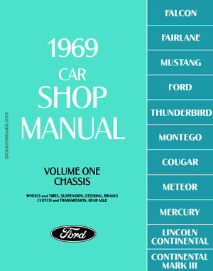
RETAINER - 2B245
DUAL MASTER CYLINDER
DISASSEMBLY
1.
Clean the outside of the master
cylinder and remove the filler cover
and diaphragm. Pour out any brake
fluid that remains in the cylinder. Dis-
card the old brake fluid.
2.*
Remove the secondary piston
stop bolt from the bottom of the cyl-
inder (Figs. 40 and 41).
3.
Remove the bleed screw, iL re-
quired.
4.
Depress the primary piston and
remove the snap ring from the retain-
ing groove at the rear of the master
cylinder bore (Fig. 42). Remove the
push rod and the primary piston as-
sembly from the master cylinder bore.
Do not remove the screw that retains
the primary return spring retainer, re-
turn spring, primary cup and protec-
tor on the primary piston. This assem-
bly is factory pre-adjusted and should
not be disassembled.
5.
Remove the secondary piston as-
sembly. Do not remove the outlet tube
seats,
outlet check valves and outlet
SECONDARY SYSTEM
BRAKE OUTLET
COVER -2166
GASKET-2167
MASTER CYLINDER -2155
SNAP RING -7821
BOOT
PUSH ROD
PRIMARY PISTON
ASSEMBLY - 2169
tTUBE SEAT-
2B220
* SECONDARY PISTON
ASSEMBLY - 2A502
• NOT USED ON POWER BRAKE EQUIPPED VEHICLES
fNOT SERVICED
•REPLACE AS AN ASSEMBLY ONLY
H 1499-B
FIG. 40— Dual Master Cylinder Disassembled—Except Disc Brakesprocarmanuals.com
Page 59 of 413

02-02-40
Brake System
02-02-40
RETAINER - 2B245
PRIMARY PISTON
ASSEMBLY-2169
GASKET-2167
RETURN SPRING
RETAINER
\ CUP
\\PROTECTOR
^\i # PISTON
fNOT SERVICED
* REPLACE AS
ASSEMBLY ONLY
*O-RING
PUMPING CUP
tVALVE
2175
SECONDARY
BRAKE SYSTEM
OUTLET
*SECONDARY PISTON
ASSEMBLY-2A502
H 1550-B
FIG. 41—Dual Master Cylinder Disassembled—Disc Brakes
check valve springs from the master
cylinder body.
open and free of foreign matter. Use
an air hose to blow out dirt and clean-
ing solvent. Place all parts on a clean
pan or paper.
3.
Inspect the master cylinder bore
for signs of etching, pitting, scoring or
rust. If it is necessary to hone the
master cylinder bore to repair dam-
age,
do not exceed allowable hone
specifications.
ASSEMBLY
1.
Dip all parts except the master
cylinder body in clean Rotunda Extra
Heavy Duty Brake Fluid.
2.
Carefully insert the complete
secondary piston and return spring as-
sembly in the master cylinder bore.
3.
Install the primary piston assem-
bly in the master cylinder bore.
4.
Depress the primary piston and
install the snap ring in the cylinder
bore groove.
5.
Install the push rod, boot and re-
tainer on the push rod, if so equipped.
Install the push rod assembly into the
primary piston. Make sure the retain-
er is properly seated and holding the
push rod securely.
6. Position the inner end of the
push rod boot (if so equipped) in the
master cylinder body retaining groove.
7.
Install the secondary piston stop
INSPECTION AND REPAIR
1.
Clean all parts in clean isopropyl
alcohol, and inspect the parts for
chipping, excessive wear or damage.
When using a master cylinder repair
kit, install all the parts supplied.
2.
Check all recesses, openings and
internal passages to be sure they are
Snap Ring Pliers
SNAP RING
H1477-C
FIG. 42—Removing Snap
Ring—Typical
INNER BRAKE
SHOE AND LINING
ASSEMBLY-2019
OUTER SHOE
RETAINING CLIPS
2066
STABILIZER
2B295
LOCATING PIN
2B296
ANCHOR PLATE
2B293(L.H.)
2B292 (R.H.)
MOVABLE CALIPER
2B119(L.H.)
2B118(R.H.)
H 1573-C
FIG. 43—Caliper Assembly—Disassembled-
All Models Except Lincoln Continentalprocarmanuals.com
Page 60 of 413
. Install the gasket (dia-
phragm) in the master cylinder filler")
02-02-41
Brake System
02-02-41
bolt and G-ring in the bottom of the
master cylinder.
8. Install the bleed screw (if so
equipped). Install the gasket (dia-
phragm) in the master cylinder filler
cover. Position the gasket as shown in
Figs.
40 and 41. Make sure the gasket
is securely seated.
9. Install the cover and gasket on
the master cylinder and secure the
cover into position with the retainer.
DISC BRAKE CALIPER
ALL MODELS EXCEPT
LINCOLN CONTINENTAL
Disassembly
1.
Remove the caliper assembly
from the vehicle as outlined in Section
2.
2.
Remove the caliper locating pins
from the caliper assembly and lift the
anchor plate from the caliper.
3.
Slide the two outer shoe retain-
ing clips off the retaining pins (Fig.
43).
4.
Remove the two retaining pins,
then remove the outer brake shoe
from the caliper.
5.
Slide the inner brake shoe out-
ward until it is free of the hold-down
springs, then remove the brake shoe.
6. Apply air pressure to the fluid
port in the caliper with a rubber
tipped nozzle (Tool 7000-DD) as
shown in Fig. 44 to remove the piston.
Place a cloth over the piston before
applying air pressure to prevent dam-
age to the piston. If the piston is
seized and cannot be forced from the
FIBER
BLOCK
CALIPER
PISTON
H 1574-B
FIG. 44 —Removing Piston From
Caliper —
All
Models Except
Lincoln Continental
caliper, tap lightly around the piston
while applying air pressure. Care
should be taken because the piston
can develop considerable force due to
pressure build-up.
7.
Remove the dust boot from the
caliper assembly.
8. Remove the rubber piston seal
from the cylinder and discard it.
Cleaning and Inspection
Clean all metal parts with isopropyl
alcohol or a suitable solvent. Use
clean, dry, compressed air to clean out
and dry the grooves and passage ways.
Be sure that the caliper bore and com-
ponent parts are completely free of
any foreign material.
Check the cylinder bore and piston
for damage or excessive wear. Replace
the piston if it is pitted, scored, or the
chrome plating is worn off.
Assembly
1.
Apply a film of clean brake fluid
to the new caliper piston seal and in-
stall it in the cylinder bore. Be sure
the seal does not become twisted and
that it is seated fully in the groove.
2.
Install a new dust boot by setting
the flange squarely in the outer groove
of the caliper bore.
3.
Coat the piston with the speci-
fied fluid and install the piston in the
cylinder bore. Spread the dust boot
over the piston as it is installed. Seat
the dust boot in the piston groove.
4.
Position the inner brake shoe so
that the ears of the shoe rests on the
top of the anchor plate bosses and be-
neath the hold-down springs.
5.
Install new caliper locating pin
insulators in the anchor plate.
6. Position the caliper on the an-
chor plate.
7.
Apply water or isopropyl alcohol
to the caliper locating pins and install
them loosely in the anchor plate. Be
sure the guide pins are free of oil,
grease or dirt.
8. Install the caliper on the spindle
as outlined under Disc Brake Caliper
Assembly.
LINCOLN CONTINENTAL
Disassembly
Do not remove the bridge bolts that
hold the two halves of the caliper to-
gether. The two caliper housings are
shown separated in Fig. 46 for illus-
tration purposes only.
1.
Remove the caliper assembly
from the car as outlined in Section 2.
2.
Remove the two attaching bolts
and the caliper splash shield (Fig. 46).
3.
Remove the two shoe and lining
assemblies.
4.
Remove the flexible brake hose
from the caliper.
5.
Remove the external transfer
tube.
6. Remove the four dust boots from
the caliper housings and piston
grooves.
7.
Clamp the caliper in a vise and
secure it by the mounting flanges on
the inboard housing (Fig. 45).
8. Remove the four pistons from
the cylinder bores with the special tool
shown in Fig. 45. To prevent cocking
with consequent damage to the piston
or bore, rotate the piston with the tool
while pulling it outward at the same
time.
Be careful to avoid scratching or
damaging the outside diameter surface
or dust boot retaining groove of the
piston. Such damage causes poor seal-
ing.
If a piston is so completely seized in
the cylinder bore that it can not be re-
moved with the special tool, the cali-
per housing must be replaced, by posi-
tioning two screwdrivers in the piston
dust boot retaining groove and prying
outward. To prevent cocking, tap the
end of the piston lightly around the
circumference with a hammer, while
the prying force is being applied. Be
careful to avoid damaging the dust
boot retainer in the caliper housing
(Fig. 46). If this method of removal is
used, the pistons must be replaced.
If the caliper dust boot retainer or
retaining groove is damaged or
scratched, pry the retainer out of the
caliper housing with screwdrivers.
Too/-T65P-2
J
18- A
H 1652-A
FIG. 45—Removing or Installing
Pistons —
Lincoln
Continentalprocarmanuals.com
Page 61 of 413

PISTON
SEAL (4)
EXTERNAL
TRANSFER
TUBE
SCREW
INBOARD
CALIPER HOUSI")
02-02-42
Brake System
02-02-42
CALIPER
ABUTMENTS
OUTBOARD
CALIPER HOUSING
DUST
BOOT RETAINING GROOVE
DUST
BOOT (4)
PISTON
SEAL (4)
EXTERNAL
TRANSFER
TUBE
SCREW
INBOARD
CALIPER HOUSING
FLEXIBLE
HOSE-^
H1367-C
FIG. 46—Caliper Assembly — Disassembled—Lincoln Continental
9. Remove the rubber piston seals
from the grooves in the cylinder bores
by carefully inserting the point of a
small knife or other pointed instru-
ment under the seal and raising the
seal up far enough to be pulled out
with the fingers.
Cleaning and Inspection
Clean all metal parts with isopropyl
alcohol or a suitable solvent (Fig. 46).
Use clean, dry, compressed air to
clean out and dry the grooves and
passage ways. Be sure that the caliper
bore and component parts are com-
pletely free of any foreign material.
Check the cylinder bores and pis-
tons for damage or excessive wear.
Replace the piston if it is pitted,
scored, or the chrome plating is worn
off. Check the caliper dust boot re-
tainer for wear or damage.
Assembly
1.
Clamp the caliper in a vise and
secure it by the mounting flange on
the inboard housing.
2.
Apply a film of clean brake fluid
to new caliper piston seals and install
them in the grooves of the cylinder
bore.
The seal should be positioned at
one area in the groove and gently
worked around. Do not use the origi-
nal seals.
3.
Install the new dust boots by set-
ting the flanges squarely in the outer
grooves of the caliper bores.
4.
Coat the pistons with the speci-
fied fluid and install the pistons inPthe
cylinder bores. Spread the dust boots
over the pistons as they are installed.
Seat the dust boots in the piston
grooves.
5.
Coat the outside diameter of the
pistons with brake fluid and install
them in the cylinder bores so that the
open end of the piston and ihe boot
retaining groove face out of the bore.
To avoid cocking, locate the piston
squarely in the bore and apply a slow
steady pressure. If a piston will not
easily go all the way into the bore, re-
move it and thoroughly inspect the
cylinder bore, the piston seal and the
installation of the seal. If the piston
still will not go in with bore in good
condition and the piston seal properly
installed, use the tool shown in Fig.
45.
Rotate the piston with the tool
while pushing it inward at the same
time.
6. Carefully install four new dust
boots on the caliper housings and pis-
tons.
Be sure that each boot is fully
seated in the groove of its respective
caliper housing and piston (Fig. 46).
Do not use the original dust boots.
7.
Install the external transfer tube.
8. Install the flexible brake hose to
the caliper.
9. Install the caliper assembly on
the spindle, and install the shoe and
lining assemblies and the splash shield
as outlined in Section 2. Check the
caliper for fluid leaks under maximum
pedal pressures. Do not move the car
until a firm brake pedal is obtained.procarmanuals.com
Page 62 of 413
 Except 390, 429 CID")
02-03-01
Specifications
02-03-01
PART
2-3
Specifications
LINING
DIMENSIONS-DRUM
BRAKES-INCHES
Vehicle
FORD, MERCURY, METEOR
Ford,
Meteor Passenger (Rivetet1
Lining) Except 390, 429 CID
Galaxie500XL, Ford LTD, LeMoyne.
Ford,
Mercury, Meteor with Disc
Brakes.
Mercury Passenger, Sta. Wag. and
Conv. Ford Meteor Station Wagon
and Convertible. 390, 429 CID
Galaxie500XL, Ford LTD, LeMoyne.
Ford,
Meteor 240, 302 CID Taxi
Only (Bonded Lining) Max. Wear
Resistance.
MONTEGO,
FAIR LANE
Passenger 250, 302 CID Except
Convertible
Station Wagon, Ranchero and
Convertible250, 302 CID.
Passenger and Convertible
351,390, 428 CID.
Station Wagon and Ranchero 351,
390,
428 CID.
FALCON
Sedan
6-Cylinder.
Station Wagon
6-Cylinder.
Sedan
8- Cylinder.
Station Wagon
8-Cylinder.
MUSTANG, COUGAR
200CID Engine.
250,
302 CID Engines.
351,390, 428 CID Engines.
IHUNDERBIRD, CONTINENTAL MARK
III
LINCOLN CONTINENTAL
Position
Primary
Secondary
Primary
Secondary
Primary
Secondary
Primary
Secondary
Primary
Secondary
Primary
Secondary
Primary
Secondary
Primary
Secondary
Primary
Secondary
Primary
Secondary
Primary
Secondary
Primary
Secondary
Primary
Secondary
Primary
Secondary
Primary
Secondary
Primary
Secondary
Front
2.50x9.34
2.50x12.12
N/A
N/A
3.00x9.34
3.00x12.12
3.00x9.34
3.00x12.12
2.25 x 8.43
2.25x10.82
2.50x8.43
2.50x10.82
2.50x8.43
2.50 x 10.82
2.25 x 7.62
2.25x9.77
2.50 x 8.43
2.50x10.82
2.25 x 8.43
2.25x10.82
2.50 x 8.43
2.50x10.82
2.25 x 7.62
2.25x9.77
2.25 x 8.43
2.25x10.82
2.50 x 8.43
2.50x10.82
N/A
N/A
N/A
N/A
Rear
2.25x9.34
2.25x12.12
.
2.25x9.34
2.25x12.12
2.25x9.34
2.25 x 12.12
2.50 x 9.34
2.50x12.12
2.00 x 8.43
2.00 x 10.82
2.00x8.43
2.00 x 10.82
2.50 x 8.43
2.50 x 10.82
1.50 x 7.62
1.50x9.77
2.00 x 8.43
2.00 x 10.82
2.00 x 8.43
2.00x10.82
2.00x8.43
2.00 x 10.75
1.50 x 7.62
1.50 x 9.77
1.75 x 8.43
1.75x10.82
2.00 x 8.43
2.00 x 10.82
2.25x9.34
2.25x12.12
3.00x9.39
3.00
x
12.21
Wear Limits Riveted: 1/32 inch from top of rivets.
Bonded:
0.030
inch total lining thicknessprocarmanuals.com
Page 63 of 413

02-03-02
Specifications
02-03-02
BORE DIAMETERS-BRAKE DRUM, WHEEL CYLINDER AND MASTER
Models
Ford,
Mercury
and
Meteor
Mont ego
and
Fairlane
Falcon
Mustang
and Cougar
Thunderbird
Continental Mark
III
Lincoln Continental
Taxi and Station Wagon
Other
Pass, except Conv. 250, 302 CID Engines
Pass, and Conv. 351, 390, 428 CID Eng.
Convertible 250, 302 CID Engines
Station and Ranchero
9 Inch Brake
-
Passenger Car
10 Inch Brake
•
Station Wagon
10 Inch Brake
•
Passenger Car
200 CID Engine
351,
390, 428 CID Engine
250,
302, CID Engine
CYLINDER
Brake Drum
Inside
Diameter
11.030
11.030
10.000
10.000
10.000
10.000
9.000
10.000
10.000
9.000
10.000
10.000
11.030
11.030
11.090
Boring Umit
(Max.)
®
11.090
11.090
10.060
10.060
10.060
10.060
9.060
10.060
10.060
9.060
10.060
10.060
11.090
11.090
11.130
Wheel Cylinder Bore Dia.
Front
0
1.094
L_ U25
1.125
1.094
1.094
1.094
1.062
0
1.094
1.125
1.062
®
1.094
1.125
N/A
N/A
N/A
Rear
®
0.938
0.938
0.875
0.875
0.875
0.938
0.844®
0.938
0.875
0.844®
0.875
0.875
0.938
0.938
0.938
Master Cylinder Bore Dia.
With Power
Brake
®
1.000
1.000
0.9375
0.9375
0.9375
0.9375
0.9375
0.9375
0.9375
1.000
1.000
1.000
1.000
1.000
1.000
Less Power
Brake
®
1.000
1.000
1.000
1.000
1.000
1.000
1.000
1.000
1.000
1.000
1.000
1.000
N/A
N/A
N/A
©Max. Runout
0.007
(DMax. Allowable Hone
0.003
CD2.755 For
Ford,
Mercury, Meteor with Disc Brakes.
2.381 For Fairlane, Montego, Falcon, Mustang, Cougar with Disc Brakes.
SHOE AND LINING DIMENSIONS-
DISC BRAKES-INCHES
® Front Wheel Cylinder cannot be honed on Falcon or Mustang with
9
inch Brakes.
Lining Material
Lining Size
Lining Area
-
Square Inches
per Segment
Lining Thickness • Nominal
Lining Wear Limit (Front
Surface
of
Shoe)
•
Max.
Lining Taper -Max.
Lining to Rotor Clearance
(Brakes Released)
Ford,
Mercury, Meteor
Thunderbird, Continen-
tal Mark
III
Bonded
7.38x2.27
Outer
5.36x2.03
Inner
12.25 Outer
8.44 Inner
0.394
0.030
0.125
0.000-0.010
Fairlane, Montego
Falcon,
Mustang,
Cougar
Bonded
6.82 x 1.80 Outer
4.90x1.84 Inner
11.30 Outer
8.80 Inner
0.333
Outer
0.362
Inner
0.030
0.125
0.000
• 0.010
Lining Material
Lining Size
Lining Area
Shoe and Lining Thickness
Lining Thickness
Shoe and Lining Maximum
Wear Limit
Lining Maximum Wear Limit
(from front surface
of
shoe)
Lining to Rotor Clearance
(brakes released)
Lincoln Continental
Riveted Fomoco
5.36x1.90
10.03 Sq. In/segment
0.600
nominal
0.436
nominal
0.231
0.066
0.000-0.010
CALIPER CYLINDER BORE DIAMETER -INCHES
TORQUE LIMITS-HUB TO SPINDLE
Ford,
Mercury, Meteor, Thunderbird, Continental Mark
2.755
Mustang, Cougar, Falcon, Fairlane and Montego
2.381
Lincoln Continental
1.938
ROTOR DIMENSIONS
Car Line
Ford,
Mercury, Meteor
Thunderbird, Continental Mark
III
Fairlane, Falcon, Montego, Mustang
and Cougar
Lincoln Continental
Norn.
Thickness
1.180
1.180
0.935
1.240
Diameter
Outside
11.72
11.72
11.29
11.960
Inside
7.785
7.785
7.355
7.785
Description
Hub and Drum or Rotor Assembly to
Front Wheel Spindle
Ft-Lbs
Rotate
hub
while torquing
to 17-25 ft-lbs. Backoff
the adjusting nut 1/2 turn
and retighten to 10-15
inch pounds while rotat-
ing wheel Selectively
posi-
tion
nut
retainer
on ad-
justing nut
so
that a set
of slots are in line with
cotter pin hole. Adjusting
nut should not be rotated
in this operation. Lock
ad-
justing nut and nut retain-
er with cotter pin so that
the cotter
pin end
does
not interfere with seating
of wheel static collector
in spindle hole.procarmanuals.com
Page 64 of 413

02-03-03
Specifications
02-03-03
ROTOR REFINISH
The following requirements must be met when resurfacing disc
brake rotors:
Rotunda Disc Brake Attachment FRE-2249-2 is the only approv-
ed tool to be used to ref inish the disc brake rotors. The step-by-
step resurfacing procedure provided with the tool must be adhered
t0" The finished braking surfaces of the rotor must be flat and
parallel within 0.0007
inch;
lateral runout must not exceed 0.003
inch total indicator reading, and the surface finish of the braking
surfaces are to be 15-80 micro inches.
On all models except Lincoln Continental the limiting dimen-
sion from the inner bearing cup to the inner rotor face must be
measured with a ball and gage bar (Rotunda FRE-70160).
On Lincoln Continental models the limiting dimension from the
inboard bearing cup to the inboard rotor face of 0.755 inch
mini-
mum and from the inboard bearing cup to the outboard rotor face
of 0.395 inch minimum must be observed.
TORQUE LIMITS -GENERAL -FT-LBS.
Parking Brake Control Assembly
Mounting Nuts and Bolts
Master Cylinder to Dash Panel Screw
Master Cylinder to Booster
Booster to Dash Panel
Disc Brake Caliper to Spindle Bolts
Disc Brake Rotor Splash Shield
to Spindle
Brake Hose to Caliper Connection Bolt
Caliper Locating Pins
Caliper Stabilizer to Anchor Plate
Bolt
Caliper Brake Shoe Clips
Caliper Bleeder Screws
Wheel Cylinder to Backing Plate Screws
Wheel Cylinder & Backing Plate
Anchor Pin Nut
Rear Brake Backing Plate to Axle
Housing:
Removable Carrier
Integral Type
Front Brake Backing Plate to Spindle
Wheel Cylinder Bleeder Screw
Brake Hose Connection to Front
Wheel Cylinder
Brake Line Connection to Rear Axle
Housing:
Removable Carrier
Integral Type
Hydraulic Tube Connections ®
3/8 x 24
7/16 x 24
1/2 x 20
9/16 x 18
Wheel to Hub and Drum or Hub and
Rotor Nuts
Ford-Mercury
Meteor
Cap Screw
12-19
Nuts 7-11
13-20
13-?0
13-20
Upper ©
110-140
Lower
90-120
9-14
17-25
25-35
8-11
6-10
6-15
10-20
20-30
50-70
IPo
25-40
6-15
12-20
30-40
25-35
10-15
10-15
10-17
10-17
70-115
Fair
lane-
Montego
Falcon
12-25
13-20
13-20
13-20
Upper CD
100-140
Lower
55-75
9-14
17-25
25-35
8-11
6-10
6-15
10 in. Brake
10-20
9 in. Brake
5-7
50-70
20-40
28-35
32-65 ®
Inch-lb.
12-20
12-19
12-19
10-15
10-15
10-17
10-17
4 lug
55-85
5 lug
70-115
Mustang-
Cougar
12-25
13-20
13-20
13-20
Upper ©
100-140
Lower
55-75
9-14
17-25
25-35
8-11
6-10
6-15
10 in. Brake
10-20
9 in. Brake
5-7
50-70
20-40
28-35
32-65 ®
Inch-lb.
12-20
12-19
12-19
10-15
10-15
10-17
10-17
4 lug
55-85
5 lug
70-115
Thunderbird
Continental
Mark III
1218
13-20
13-20
Upper ©
110-140
Lower
90-120
9-14
17-25
25-35
8-11
6-10
6-15
10-20
50-70
6-15
30-40
10-15
10-15
10-17
10-17
70-115
Lincoln
Continental
Dash Panel
10-20
Inst. Panel
712
13-20
13-20
100-140
9-14
7-9
6-15
10-20
30-35
6-15
10-15
10-15
10-17
10-17
70-115
® The upper bolt must be tightened first.
® On front disc brake calipers 6-15 ft-lbs.
® All hydraulic lines must be tightened to the specified torque value and be free of fluid leakage.procarmanuals.com
 1
1 2
2 3
3 4
4 5
5 6
6 7
7 8
8 9
9 10
10 11
11 12
12 13
13 14
14 15
15 16
16 17
17 18
18 19
19 20
20 21
21 22
22 23
23 24
24 25
25 26
26 27
27 28
28 29
29 30
30 31
31 32
32 33
33 34
34 35
35 36
36 37
37 38
38 39
39 40
40 41
41 42
42 43
43 44
44 45
45 46
46 47
47 48
48 49
49 50
50 51
51 52
52 53
53 54
54 55
55 56
56 57
57 58
58 59
59 60
60 61
61 62
62 63
63 64
64 65
65 66
66 67
67 68
68 69
69 70
70 71
71 72
72 73
73 74
74 75
75 76
76 77
77 78
78 79
79 80
80 81
81 82
82 83
83 84
84 85
85 86
86 87
87 88
88 89
89 90
90 91
91 92
92 93
93 94
94 95
95 96
96 97
97 98
98 99
99 100
100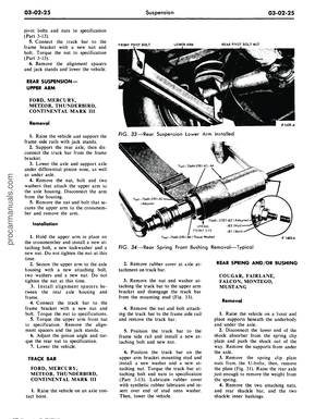 101
101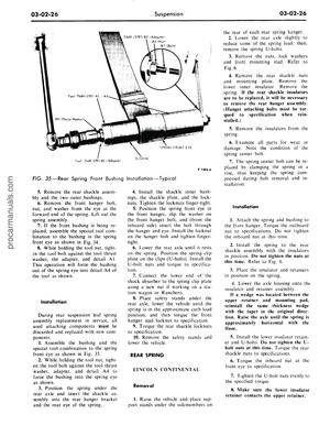 102
102 103
103 104
104 105
105 106
106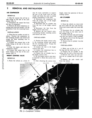 107
107 108
108 109
109 110
110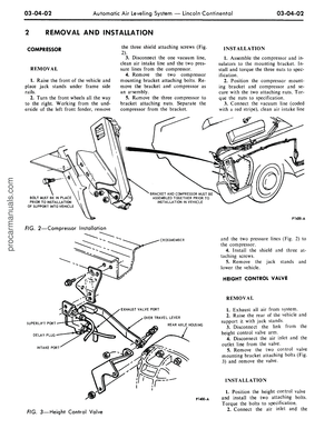 111
111 112
112 113
113 114
114 115
115 116
116 117
117 118
118 119
119 120
120 121
121 122
122 123
123 124
124 125
125 126
126 127
127 128
128 129
129 130
130 131
131 132
132 133
133 134
134 135
135 136
136 137
137 138
138 139
139 140
140 141
141 142
142 143
143 144
144 145
145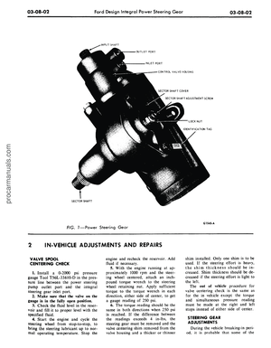 146
146 147
147 148
148 149
149 150
150 151
151 152
152 153
153 154
154 155
155 156
156 157
157 158
158 159
159 160
160 161
161 162
162 163
163 164
164 165
165 166
166 167
167 168
168 169
169 170
170 171
171 172
172 173
173 174
174 175
175 176
176 177
177 178
178 179
179 180
180 181
181 182
182 183
183 184
184 185
185 186
186 187
187 188
188 189
189 190
190 191
191 192
192 193
193 194
194 195
195 196
196 197
197 198
198 199
199 200
200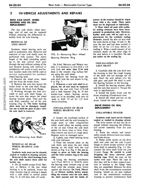 201
201 202
202 203
203 204
204 205
205 206
206 207
207 208
208 209
209 210
210 211
211 212
212 213
213 214
214 215
215 216
216 217
217 218
218 219
219 220
220 221
221 222
222 223
223 224
224 225
225 226
226 227
227 228
228 229
229 230
230 231
231 232
232 233
233 234
234 235
235 236
236 237
237 238
238 239
239 240
240 241
241 242
242 243
243 244
244 245
245 246
246 247
247 248
248 249
249 250
250 251
251 252
252 253
253 254
254 255
255 256
256 257
257 258
258 259
259 260
260 261
261 262
262 263
263 264
264 265
265 266
266 267
267 268
268 269
269 270
270 271
271 272
272 273
273 274
274 275
275 276
276 277
277 278
278 279
279 280
280 281
281 282
282 283
283 284
284 285
285 286
286 287
287 288
288 289
289 290
290 291
291 292
292 293
293 294
294 295
295 296
296 297
297 298
298 299
299 300
300 301
301 302
302 303
303 304
304 305
305 306
306 307
307 308
308 309
309 310
310 311
311 312
312 313
313 314
314 315
315 316
316 317
317 318
318 319
319 320
320 321
321 322
322 323
323 324
324 325
325 326
326 327
327 328
328 329
329 330
330 331
331 332
332 333
333 334
334 335
335 336
336 337
337 338
338 339
339 340
340 341
341 342
342 343
343 344
344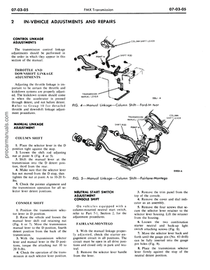 345
345 346
346 347
347 348
348 349
349 350
350 351
351 352
352 353
353 354
354 355
355 356
356 357
357 358
358 359
359 360
360 361
361 362
362 363
363 364
364 365
365 366
366 367
367 368
368 369
369 370
370 371
371 372
372 373
373 374
374 375
375 376
376 377
377 378
378 379
379 380
380 381
381 382
382 383
383 384
384 385
385 386
386 387
387 388
388 389
389 390
390 391
391 392
392 393
393 394
394 395
395 396
396 397
397 398
398 399
399 400
400 401
401 402
402 403
403 404
404 405
405 406
406 407
407 408
408 409
409 410
410 411
411 412
412