Page 9 of 413

1A Black Cloth & Vinyl
IB Med. Blue Cloth/Lt. Blue Vinyl
IB Med. or Lt. Blue Vin")
01-01-05
Vehicle Identification
01-01-05
INTERIOR TRIM CODES
Code Trim Schemes
1A Black Vinyl (Cougar, Falcon)
1A Black Cloth & Vinyl
IB Med. Blue Cloth/Lt. Blue Vinyl
IB Med. or Lt. Blue Vinyl
IB Dk. Blue Cloth & Vinyl
(Lincoln,
T-Bird, Mark III, Mercury)
IB Lt. Blue Cloth & Vinyl
(Ford,
Montego, Meteor)
ID Dk. Red Cloth and Vinyl
IF Med. Saddle Vinyl (Cougar)
1G Dk. Ivy Gold Cloth & Vinyl
1G Lt. Ivy Gold Vinyl (Cougar)
IK Lt. Aqua Cloth and/or Vinyl
IP
Med.
Grey Cloth & Vinyl (Mark III)
1Y Lt. Nugget Gold Vinyl (Cougar-Falcon)
1Y Lt. Nugget Gold Cloth & Vinyl
2A Black Vinyl
2A Black Leather & Vinyl (Lincoln)
2A Black Leather (Mark III)
2B Dk. or Lt. Blue Vinyl
2B Dk. Blue Leather & Vinyl (Lincoln)
2B Dk. Blue Leather (Mark III)
2D Dk. Red Vinyl
2D Dk. Red Leather & Vinyl (Lincoln)
2D Dk. Red Leather (Mark III)
2F Med. Saddle Vinyl (Cougar)
2F
Med.
Saddle Leather & Vinyl (Lincoln)
2F Med. Saddle Leather (Mark III)
2G Lt. or Dk. Ivy Gold Vinyl
2G Dk. Ivy Gold Leather & Vinyl (Lincoln)
2G Dk. Ivy Gold Leather (Mark III)
2K Lt. Aqua Vinyl
2K Lt. Aqua Leather & Vinyl (Lincoln)
2K Lt. Aqua Leather (Mark III)
2P
Med.
Grey Leather (Mark III)
2U Pastel Parchment w/Black Leather (Mark III)
2W Whitew/Black Vinyl
2W White w/Black Leather & Vinyl (Lincoln)
2W Whitew/Black Leather (Mark III)
2Y Lt. Nugget Gold Vinyl
2Y Lt. Nugget Gold Leather & Vinyl (Lincoln)
2Y Lt. Nugget Gold Leather (Mark III)
3A Black w/Red Knit and/or Vinyl (Mustang,
Montego)
3A Black Knit and/or Vinyl
3A Black Cloth & Vinyl
3A Black Leather & Vinyl (Lincoln)
3B Lt. Blue Knit and/or Vinyl
3B Lt. or Dk. Blue Cloth & Lt. Blue Vinyl
3B Lt. Blue Cloth & Vinyl
(Fairlane,
Ford,
Montego, Meteor)
3B Med. Blue Cloth & Lt. Blue Vinyl
3B Dk. Blue Cloth & Vinyl (T-Bird, Mercury)
3B Dk. Blue Leather & Vinyl (Lincoln)
3D Dk.Red Cloth & Vinyl
3D Dk. Red Knit and/or Vinyl
3G Dk. Ivy Gold Cloth & Vinyl
3G Dk. Ivy Gold Leather & Vinyl (Lincoln)
3K Lt. Aqua Cloth & Vinyl
3W White w/Black Knit and/or Vinyl
3W Whitew/Black Leather & Vinyl (Lincoln)
3Y Lt. Nugget Gold Cloth & Vinyl
3Y Lt. Nugget Gold Knit and/or Vinyl (T-Bird)
4A Black Cloth & Vinyl
4A Black Knit and/or Vinyl
4B Dk. Blue Vinyl
4B Dk. or Lt. Blue Vinyl
4D Dk.Red Vinyl
4G Dk. Ivy Gold Cloth & Vinyl
4G Dk. Ivy Gold Vinyl
4K Lt. Aqua Vinyl
4W White w/Black Vinyl
4Y Lt. Nugget Gold Knit and/or Vinyl
5A Black Cloth & Vinyl
5A Black Knit and/or Vinyl
5A Black Leather & Vinyl (Lincoln)
5B Lt. Blue Cloth and/or Vinyl
5B Lt. Blue Knit and/or Vinyl
5B Dk. Blue Leather & Vinyl (Lincoln)
5B Dk. Blue Cloth & Vinyl (Mercury)
5D Dk.Red Cloth & Vinyl (Montego)
INTERIOR TRIM CODES-(continued)
Code Trim Schemes
5D Dk. Red Knit and/or Vinyl
5D Dk. Red Leather & Vinyl (Lincoln)
5F
Med.
Saddle Leather & Vinyl (Lincoln)
5G Dk. Ivy Gold Knit and/or Vinyl
5G Dk. Ivy Gold Cloth & Vinyl
5G Dk. Ivy Gold Leather & Vinyl (Lincoln)
5K Lt. Aqua Cloth & Vinyl (Montego)
5K Lt. Aqua Vinyl
5K Lt. Aqua Leather & Vinyl (Lincoln)
5W White w/Black Knit and/or Vinyl
5W White w/Black Leather & Vinyl (Lincoln)
5Y Lt. Nugget Gold Cloth & Vinyl
5Y Lt. Nugget Gold Knit and/or Vinyl (Mustang,
Fairlane)
5Y Lt. Nugget Gold Leather & Vinyl (Lincoln)
6A Black Knit and/or Vinyl
6A Black Cloth & Vinyl (Lincoln)
6A Black Leathe; & Vinyl (Cougar)
6B Dk. or Lt. Blue Vinyl
6B Dk. Blue Leather & Vinyl (Cougar)
6D Dk. Red Knit and/or Vinyl
6D Dk.Red Leather & Vinyl (Cougar)
6F
Med.
Saddle Leather I Vinyl
6G Dk. Ivy Gold Vinyl
6G Dk. Ivy Gold Leather & Vinyl (Cougar)
6K Lt. Aqua Vinyl
6K Lt. Aqua Leather & Vinyl (Cougar)
6W White w/Black Vinyl
6Y Lt. Nugget Gold Vinyl
6Y Lt. Nugget Gold Leather & Vinyl (Cougar)
7A Black Vinyl
7A Black Cloth & Vinyl (Fairlane)
7A Black Leather & Vinyl (Lincoln)
7B Lt. Blue Vinyl (Cougar, Montego, Ford)
7B Dk. Blue Cloth & Vinyl
7B Dk. Blue Leathe; & Vinyl (Lincoln)
7D Dk. Red Vinyl (Mustang)
7D Dk. Red Cloth & Vinyl
7G Dk. Ivy Gold Cloth and/or Vinyl
7G Dk. Ivy Gold Leather & Vinyl (Lincoln)
7K Lt. Aqua Cloth & Vinyl
7W White w/Black Vinyl
7W White Leather & Vinyl (Lincoln)
7Y Lt. Nugget Gold Cloth & Vinyl
7Y Lt. Nugget Gold Vinyl
(Ford,
Meteor, Mustang)
8A Black Knit and/or Vinyl
8A Black Leather & Vinyl (T-Bird)
8B Dk. or Lt. Blue Knit and/or Vinyl
8D Dk. Red Knit and/or Vinyl
8F Med. Saddle Knit and/or Vinyl
8G Dk. Ivy Gold Knit and/or Vinyl
8K Lt. Aqua Knit and/or Vinyl
8W White w/Black and/or Vinyl
8W White w/Black Leather & Vinyl (T-Bird)
8Y Lt. Nugget Gold Knit and/or Vinyl
9A Black Knit and/or Vinyl
9A Black Cloth & Vinyl (Ford, Meteor)
9B Lt. Blue Knit and/or Vinyl
9B Dk. Blue Cloth & Vinyl (Ford, Meteor)
9D Dk. Red Knit and/or Vinyl
9D Dk. Red Cloth & Vinyl (Ford-Meteor)
9G Dk. Ivy Gold Cloth & Vinyl
9K Lt. Aqua Cloth & Vinyl
9Y Lt. Nugget Gold Cloth and/or Vinyl
9Y Lt. Nugget Gold Knit and/or Vinyl
AA(1W)
White Vinyl
With Black (Cougar)
AA Black Cloth & Vinyl (Lincoln)
AB(1W) White Vinyl With Blue (Cougar)
AB Lt. Blue Cloth & Vinyl (Lincoln)
AD(1W) White Vinyl With Red (Cougar)
AG(1W) White Vinyl With Ivy Gold (Cougar)
AG Lt. Ivy Gold Cloth & Vinyl (Lincoln)
AK (1W) White Vinyl With Aqua (Cougar)
AK Lt. Aqua Cloth & Vinyl (Lincoln)
AL Lt. Silver Cloth & Vinyl (Lincoln)
AY Lt. Nugget Gold Cloth & Vinyl (Lincoln)
AY(1W) White Vinyl With Nugget Gold (Cougar)
BA(2W) White Vinyl With Black (Cougar)
BA Black Vinyl (Fairlane)
BB(2W) White Vinyl With Blue (Cougar)procarmanuals.com
Page 10 of 413

Code Trim Schemes
BB Lt. Blue Vinyl (Fairlane)
BB Lt. Blue Leather & Vinyl (Lincoln)
BD(2W) ..White Vinyl With Red (Cou")
01-01-06
Vehicle Identification
01-01-06
INTERIOR TRIM CODES-(continued)
Code Trim Schemes
BB Lt. Blue Vinyl (Fairlane)
BB Lt. Blue Leather & Vinyl (Lincoln)
BD(2W) ..White Vinyl With Red (Cougar)
BG(2W) White
Vinyl
With Ivy Gold (Cougar)
BG Lt. Ivy Gold Leather & Vinyl (Lincoln)
BK(2W) White Vinyl With Aqua (Cougar)
BY(2W) White Vinyl With Lt. Nugget Gold (Cougar)
BY Lt. Nugget Gold Vinyl (Fairlane)
CA Black Cloth & Vinyl
CA Black Vinyl (Montego)
CB Dk. Blue Cloth & Vinyl
CB Lt. Blue Vinyl (Montego)
CD Dk. Red Cloth & Vinyl
CD Dk. Red Vinyl
CG Dk. Ivy Gold Cloth & Vinyl
CG Lt. Ivy Gold Leather & Vinyl (Lincoln)
CK Lt. Aqua Cloth & Vinyl
CY Lt. Nugget Gold Cloth & Vinyl
CY Lt. Nugget Gold Vinyl (Montego)
DA Black Cloth & Vinyl
DA(4W) White
Vinyl
With Black (Cougar)
DA Black Knit and/or Vinyl
DB Dk. Blue Cloth & Vinyl
DB Dk. Blue Vinyl (Mercury)
DB(4W) White Vinyl With Blue (Cougar)
DD(4W) White Vinyl With Red (Cougar)
DD Dk. Red Knit and/or Vinyl
DD Dk. Red Cloth & Vinyl
DG Dk. Ivy Gold Vinyl
DG Dk. Ivy Gold Cloth & Vinyl
DK Lt. Aqua Cloth & Vinyl
DW White w/Black Knit and/or Vinyl
DY Lt. Nugget Gold Cloth & Vinyl
DY Lt. Nugget Gold Vinyl (Mercury)
EA Black Knit and/or Vinyl
EA Black Cloth & Vinyl
EB Dk. Blue Cloth & Vinyl
ED Dk. Red Cloth & Vinyl
EG Dk. Ivy Gold Cloth & Vinyl
EK Lt. Aqua Cloth & Vinyl
EW White w/Black Knit and/or Vinyl
EY Lt. Nugget Gold Cloth & Vinyl
FA Black Knit and/or Vinyl
FA(6W) White
Vinyl
With Black (Cougar)
FB Lt. or Dk. Blue Vinyl
FB(6W) White Vinyl With Blue (Cougar)
FD Dk. Red Knit and/or Vinyl
FD(6W) White Vinyl With Red (Cougar)
FG Dk. Ivy Gold Vinyl
FG(6W) White
Vinyl
With Ivy Gold (Cougar)
FK(6W) White Vinyl With Lt. Aqua (Cougar)
FW White w/Black Knit and/or Vinyl
FY Lt. Nugget Gold Vinyl
FY(6W) White Vinyl With Nugget Gold (Cougar)
GA Black Vinyl
GB Lt. Blue Vinyl
GD Dk. Red Vinyl
GG Dk. Ivy Gold Vinyl
GY Lt. Nugget Gold Vinyl
HA Black Knit and/or Vinyl
HA(8W) White Vinyl With Black (Cougar)
HA Black Leather & Vinyl (Mercury)
HB Lt. Blue Vinyl
HB (8W) White Vinyl With Blue (Cougar)
HD Dk. Red Vinyl
HD Dk. Red Leathe; & Vinyl (Mercury)
HD(8W) White Vinyl With Dk. Red (Cougar)
HG Dk. Ivy Gold Vinyl
HG(8W) White Vinyl With Ivy Gold (Cougar)
HK Lt. Aqua Vinyl
HK(8W) White Vinyl With Lt. Aqua (Cougar)
HW White w/Black Leather & Vinyl (Mercury)
HW White w/Black Vinyl (Fairlane)
INTERIOR TRIM CODES-(contlnuad)
Code Trim Schemes
HY(8W) White Vinyl With Nugget Gold (Cougar)
HY Lt. Nugget Gold Knit and/or Vinyl
JA Black Knit and/or Vinyl
JB Lt. Blue Cloth & Vinyl (Lincoln)
JG Lt. Ivy Gold Cloth & Vinyl
JW .....White w/Black Knit and/or Vinyl
JY Lt. Nugget Gold Knit and/or Vinyl
JY Lt. Nugget Gold Cloth & Vinyl (Lincoln)
KA Black Knit and/or Vinyl
KA Black Cloth & Vinyl (Ford-Mercury-Meteor)
KA Black Leather & Vinyl (Lincoln)
KB Dk. Blue Cloth & Vinyl
KB .....Med. Blue Cloth & Lt. Blue Vinyl (Ford-Montego)
KB Dk. Blue Leather & Vinyl (Lincoln)
KD Dk. Red Cloth & Vinyl
KG Dk. Ivy Gold Leather & Vinyl (Lincoln)
KG Dk. Ivy Gold Cloth & Vinyl
KL Lt. Silver Leather & Vinyl (Lincoln)
KW White W/Black Leather & Vinyl (Lincoln)
KY Lt. Nugget Gold Knit and/or Vinyl
KY Lt. Nugget Gold Cloth & Vinyl
LA Black Knit and/or Vinyl
LA Black Leather & Vinyl (Lincoln)
LB Lt. Blue Knit and/or Vinyl
LB Dk. Blue Leather & Vinyl (Lincoln)
LD Dk. Red Knit and/or Vinyl
LE Lt. & Med. Beige Vinyl
LG Dk. Ivy Gold Leather & Vinyl (Lincoln)
LW White w/Black Knit and/or Vinyl
LW White w/Black Leather & Vinyl (Lincoln)
LY Lt. Nugget Gold Knit and/or Vinyl
MA Black Vinyl
MB Lt. Blue Vinyl
MD
Dk
Red Vinyl
MW White w/Black Vinyl
NA Black Knit and/or Vinyl
NB Lt. Blue Vinyl
NY Lt. Nugget Gold Knit and/or Vinyl
PA Black Vinyl
PB Lt. Blue Vinyl
PY Lt. Nugget Gold Vinyl
QA Black Knit and/or Vinyl
)B
. Lt
Blue Vinyl
JW White Knit and/or Vinyl
Lt. Nugget Gold Vinyl
Black Knit and/or Vinyl
RA Black Leather & Vinyl
RB Lt. Blue Knit and/or Vinyl
RD Dk. Red Knit and/or Vinyl
RD Dk. Red Leather & Vinyl
RW White w/Black Leather & Vinyl
RW White W/Black Knit and/or Vinyl
RY Lt. Nugget Gold Knit and/or Vinyl
SB Lt. Blue Leather & Vinyl (Lincoln)
SG Lt. Ivy Gold Leather & Vinyl (Lincoln)
TG Lt. Ivy Gold Leather & Vinyl (Lincoln)
VA Black Knit and/or Vinyl
VB
Dk
Blue Vinyl
VG Dk. Ivy Gold Vinyl
VW White w/Black Knit and or Vinyl
VY Lt. Nugget Gold Vinyl
WA Black Knit and/or Vinyl
WW White w/Black Knit and/or Vinyl
WY Lt. Nugget Gold Knit and/or Vinyl
YA Black Cloth & Vinyl
YB Dk. Blue Cloth & Vinyl
YD Dk. Red Cloth & Vinyl
YG Dk. Ivy Gold Cloth
&
Vinyl
YK Lt. Aqua Cloth & Vinyl
YY Lt. Nugget Gold Cloth & Vinyl
ZA Black Cloth & Vinyl
ZB Dk. Blue Cloth & Vinyl
ZG Dk. Ivy Gold Cloth & Vinylprocarmanuals.com
Page 11 of 413

01-01-07
Vehicle Identification
01-01-07
DATE CODES
A number signifying the date precedes the month code letter. A
second-year code letter will be used if the model exceeds 12 months.
Month
Code
First Year
Code
Second Year
January
February
March
April
May
June
July
August
September
October
November
December
....A..
...B..
...C.
...D..
...E..
...
F..
...
G.
...H.
...J..
..
K.
. ...L.
...M.
DISTRICT CODES (DSO)
Units built on a Domestic Special Order, Foreign Special Order,
or other special orders will have the complete order number in
this space. Also to appear in this space is the two-digit code number
of the District which ordered the unit. If the unit is a regular
production unit, only the District code number will appear.
FORD
Code
District
Code
District
11...
13
...
15...
16...
17...
21...
22
...
24...
25...
28...
32....
33...
35...
37...
38....
41...
43...
44...
46....
47...
Boston
...New York
Newark
...Philadelphia
Washington
Atlanta
Charlotte
...Jacksonville
Richmond
. ...Louisville
. ...Cleveland
.... Detroit
Lansing
...Buffalo
... .Pittsburgh
Chicago
Milwaukee
Twin Cities
...Indianapolis
Cincinnati
51
53
54
55
56
61
62
63
64
65
71
72
73
74
75
83
84
85
89
90's
..
... Denver
.. .Kansas City
.. Omaha
...St. Louis
.. Davenport
.. Dallas
... Houston
.. Memphis
.. New Orleans
.. .Oklahoma City
... Los Angeles
...San Jose
...Salt Lake City
...Seattle
.. .Phoenix
.. Government
... Home Office Reserve
.. American Red Cross
...Transportation Services
...Export
LINCOLN-MERCURY
Code
District
Code
District
11
15
16
17
21
22
23
26
31
32
33
Boston
New York
Philadelphia
Washington
Altanta
Dallas
Jacksonville
Memphis
Buffalo
Cincinnati
Cleveland
34
41
42
46
51
52
53
54
84
90's...
... Detroit
.. Chicago
..
St.
Louis
... Twin Cities
Denver
Los Angeles
Oakland
Seattle
Home Office Reserve
Export
FORD
OF
CANADA
Code
District
Code
District
Bl
B2
B3
II thru
17..
Central
Eastern
Atlantic
Export
B4.
B6.
B7.
Midwestern
Western
. Pacific
Note:
Canadian Lincoln-Mercury units use prefix
"A" in
place of«"B".procarmanuals.com
Page 12 of 413

02-01-01
02-01-01
GROUP
2
PART
2-1
PAGE
General Brake Service 02-01-01
PART
2-2
Brake System 02-02-01
PART
2-3
Specifications
PAGE
02-03-01
Part
2-1
General Brake Service
COMPONENT INDEX
ANTI SKID CONTROL SYSTEM
Tests
BRAKE BOOSTER
Adjustments
Cleaning
and
Inspection
Tests
BRAKE PEDAL
Free Height Test
Total Travel Test
DISC BRAKES
Cleaning
and
Inspection
Service Precautions
DRUM BRAKES
Cleaning
and
Inspection
HYDRAULIC SYSTEM BLEEDING
PARKING BRAKE CONTROL
Vacuum Release Test
PARKING BRAKE LINKAGE
Adjustment
PRESSURE DIFFERENTIAL VALVE
Adjustment (Centralize)
MODEL APPLICATION
All
Models
01-04
01-07
01-02
01-01
01-01
01-07
01-07
01-08
01-05
01-07
Ford
N/A
01-03
01-03
Mercury
N/A
01-03
01-03
Meteor
N/A
01-03
01-03
Cougar
N/A
N/A
01-03
Fairlane
N/A
N/A
01-03
F
alcon
N/A
N/A
01-03
Montego
N/A
N/A
01-03
Mustang
N/A
N/A
01-03
Lincoln-
Continental
N/A
01-03
01-04
Thunderbird
01-03
01-03
01-04
Continental-
Mark III
01-03
01-03
01-04
A page number indicates that the item
is for the
vehicle listed
at
the head
of the
column.
N/A indicates that the item
is not
applicable
to
the vehicle listed.
1 BRAKE SYSTEM TESTS
Always check
the
fluid level
in the
master cylinder before performing
the
test procedures.
If the
fluid level
is not
within
1/4
inch
of the top of the mas-
ter cylinder reservoirs,
add
Ford
Brake Fluid
—
Extra Heavy Duty —
Part Number C6AZ-19542-A
(ESA-
M6C25-A)
or
equivalent
for all
brake
applications.
The
extra heavy duty
brake fluid
is
colored blue
for
identifi-
cation purposes.
Do not mix low tem-
perature brake fluids with
the
speci-
fied brake fluid.
Should
one of the
wheel brakes
be
locked
and the
vehicle must
be
moved,
open
the
bleeder screw long enough
to
let
out a few
drops
of
brake fluid.
This bleeding operation will release
the brakes
but
will
not
correct
the
cause
of
trouble.
BRAKE PEDAL FREE
HEIGHT
AND
TRAVEL
MEASUREMENTS
With
the
engine running
for
full
power brake operation, measure
the
brake pedal free height,
and
check
the
brake pedal travel with
the use of the
Brake Pedal Pressure Gauge, Tool
WRE-5OO-5O
as
follows:
BRAKE PEDAL FREE HEIGHT
MEASUREMENT
1.
Insert
a
slender, sharp pointed
prod through
the
carpet
and
sound
deadener
to the
dash panel metal
and
measure
the
distance
to the
brake
pedal
(Fig. 1).
2.
If the
position
of the
pedal
is not
within specification, check
the
brake
pedal linkage
for
missing, worn,
or
damaged bushings,
or
loose attaching
bolts
and
replace them,
if
required.
3.
If the
pedal free height
is
still
out
of
specification, check
the
brake
pedal booster
or
master cylinder
to be
sure
the
correct parts
are
installed.
Replace
the
worn
or
damaged parts
as
necessary.
BRAKE PEDAL TRAVEL
MEASUREMENT
1.
Install
a
Brake Pedal Effort
Gauge
on the
brake pedal
pad
(Fig. 2).
2.
Hook
a
steel measuring tape
to
the brake pedal
as
shown
in Fig. 1.
Measure
and
record
the
distance from
the brake pedal free height position
to
the reference point, which
is at the six
procarmanuals.com
Page 13 of 413

02-01-02
Brakes
02*01-02
STEERING
WHEEL RIW
TOEBOARD
OR
DASH
METAL
CHECKING
POINTS
STEERING
COLUMN-
STEEL
MEASURING TAPE
VEHICLE
FORD,
MERCURY AND METEOR
FORD,
MERCURY AND METEOR
FORD,
MERCURY AND METEOR
FORD,
MERCURY AND METEOR
FAIRLANE,
MONTEGO AND FALCON
FAIRLANE,
MONTEGO AND FALCON
MUSTANG
AND COUGAR
MUSTANG
AND COUGAR
THUNDERBIRD
CONTINENTAL
MARK III
LINCOLN
CONTINENTAL
TYPE
NON-POWER
DRUM
POWER
DRUM & DISC
NON-POWER
DISC
POLICE
POWER DISC
NON-POWER
DRUM
POWER
DISC
NON-POWER
DRUM
POWER
DISC
POWER
DISC
POWER
DISC
POWER
DISC
PEDAL
FREE
HEIGHT-A
8.09-7.17
6.18-5.99
8.65-7.82
7.58-6.72
8.13-6.91
7.25-5.71
7.49-6.43
6.25-5.56
PEDAL
FREE
HEIGHT-B"
5.96-5.04
5.96-5.04
6.50-5.50
PEDAL
TRAVEL-C
3.10
3.27
2.18
3.27
2.90
2.35
2.58
1.75
3.00
3.00
2.25
NOTE:AgB
DIMENSION TO BE MEASURED TO SHEET METAL
C
DIMENSION TO BE MEASURED PARALLEL TO THE VERTICAL CENTERLINE OF THE
STEERING
COLUMN WITH A 50 POUND LOAD APPLIED TO THE CENTERLINE OF THE
BRAKE
PEDAL PAD. (CHECKS ON POWER BRAKE VEHICLES MADE WITH ENGINE RUNNING
H1630-A
FIG. 1 — Brake Pedal Height and Travel Measurements
Tool-WRE-l
HI525-A
FIG.
2—Brake Pedal Effort Gauge Installed
o'clock position on the steering wheel
rim.
3.
With the steel tape still hooked
to the brake pedal depress the brake
pedal by pressing downward on the
brake pedal effort gauge. Apply a 50
pound load to the center of the pedal
by observing the pressure gauge, and
measure the distance from the brake
pedal to the fixed reference point on
the steering wheel rim parallel to the
centerline of the steering column.
4.
The difference between the brake
pedal free height and the depressed
pedal measurement under a 50 pound
load should be within the specified
maximum pedal travel service specifi-
cation B in Fig. I.
5.
If the pedal travel is more than
the specified maximum shown in Fig.
1,
dimension C, make several sharp
reverse stops (equivalent to 50 pounds
pedal pressure) with a forward stop
before each. Move the vehicle in rev-
erse and forward for a distance of ap-
proximately ten feet; then, apply the
brakes sharply and hold the brake
pedal down until the vehicle is com-
pletely stopped. This will actuate the
brake self-adjusters. If these stops do
not bring the brake pedal travel within
specification, make several additional
forward and reverse stops as outlined
above.
6. If the second series of stops do
not bring the brake pedal travel within
specification, remove the brake drums
and check the brake adjusters to make
sure they are functioning. Check the
brake linings for wear or damage. Re-
pair or replace all worn or damaged
parts and non-functioning adjusters.
Adjust the brake lining outside diame-
ter to the approximate inside diameter
of the brake drum with Rotunda Tool
HRE-8650 (Fig. 12, Part 2-2).
7.
If all the brake adjusters, brake
drums and linings are functional and
the brake travel is not within specifi-
cations, check the pedal linkage for
missing or worn bushings, or loose at-
tachments. Bleed the brakes and cen-
tralize the differential valve.
POWER BRAKE
FUNCTIONAL TEST
1.
Check the hydraulic brake sys-
tem for leaks or insufficient fluid.
2.
With the transmission in neutral,
stop the engine and apply the parking
brake. Depress the brake pedal several
times to exhaust all vacuum in the
system.
3.
With the engine shut off and all
vacuum in the system exhausted, dep-
ress the pedal, and hold it in the ap-
plied position. Start the engine If theprocarmanuals.com
Page 14 of 413

02-01-03
Brakes
02-01-03
vacuum system is operating, the pedal
will tend to fall away under foot pres-
sure and less pressure will be required
to hold the pedal in the applied posi-
tion. If no action is felt, the vacuum
booster system is not functioning.
If the brake pedal movement feels
spongy, bleed the hydraulic system to
remove air from the system. Refer to
Hydraulic System Bleeding, Part 1,
Section 2.
VACUUM TESTS—VACUUM
RELEASE PARKING BRAKES
Visually check the operation of the
brake linkage as the brake pedal is
depressed. Then, check the operation
of the brake linkage when the manual
release lever is activiated. These
checks should indicate whether the
manual parking brake control linkage
is operating properly or requires re-
pair or adjustment due to inability of
the parking brake to hold against
moderate vehicle movement. Perform
tests of the parking brake system and
controls after making certain the link-
age and manual controls operate
properly.
When testing a parking brake vacu-
um release system, a minimum of 10
inches of vacuum (Hg.) should be
available at all points where vacuum is
applied. This can be checked with a
Rotunda Fuel Pump Tester Gauge
(ARE345) and two Distributor Tester
hose adapters (Marked Q) connected
together with a coupling. This allows
the Fuel Pump Tester Gauge hose to
be adapted to any other vacuum hose
or rubber connector in the vacuum
systems.
Failure to maintain 10 inches of
vacuum (Hg.) during vacuum system
tests could be caused by a loose hose
connection, resulting in a vacuum
leak. When checking for vacuum be-
tween two points, trace the hose along
the entire routing to be sure it is not
crossed with another hose and con-
nected to the wrong connection.
All of the vacuum parking brake
control checks are to be performed
with the engine running at idle speed.
Leaks in the parking brake hoses or
a disconnected or improperly con-
nected hose can usually be found by
listening for a hissing sound along the
hose routings. Under no circumstances
should air pressure be applied to the
vacuum system as the actuator dia-
phragm in the parking brake vacuum
motor may be damaged.
1.
Start the engine and run it at
idle speed. With the transmission shift
control in neutral, depress the parking
brake pedal to apply the parking
brake. Move the transmission shift
control to D range and observe the
parking brake pedal to see that the
pedal moves upward and the parking
brake releases. If the parking brake
releases, the parking brake vacuum
control is working properly.
2.
If the parking brake does not re-
lease, test for vacuum at the steering
column neutral switch port in the
junction block, vacuum lines and the
parking brake release vacuum motor.
Use the Rotunda Vacuum and Fuel
Pump Tester 345. This can be accom-
plished by removing the hose from
each component and attaching it to
the vacuum gauge. Connect two dis-
tributor tester vacuum hose adapters
together with a coupling as a connec-
tor to attach the gauge. A minimum
of ten inches of vacuum is required to
actuate the parking brake vacuum
motor. Do not remove any of the vac-
uum hoses from the junction block
unless the junction block is being re-
placed, as the plastic nipples are thin
and very brittle and damage may re-
sult. If a minimum reading is not
present when checking each of the
aforementioned components, they
must be replaced.
ROAD TEST
A road test should be conducted
only when the operator is sure the
brakes will stop the vehicle.
If the road test reveals one or more
problem conditions, correct all mal-
functions of the vacuum system, brake
booster and hydraulic system prior to
removing brake drums, brake calipers,
brake shoes and linings or backing
plates.
ANTI-SKID CONTROL
SYSTEM TESTS
No adjustments or repairs are to be
performed on the skid control system.
Damaged or worn parts are to be re-
placed.
Refer to Ford Car and Truck Diag-
nosis Manual for Testing procedures.
COMMON ADJUSTMENTS AND REPAIRS
PARKING BRAKE LINKAGE
ADJUSTMENT
FORD, MERCURY, METEOR,
FAIRLANE, MONTEGO,
FALCON, MUSTANG
AND COUGAR
Check the parking brake cables
when the brakes are fully released. If1
the cables are loose, adjust them as
follows:
1.
Fully release the parking brake
pedal by pulling the release lever.
2.
Depress the parking brake pedal
until it is engaged in the first notch of
the control. On a vacuum release
brake, the first notch will be approxi-
mately two inches of pedal travel.
3.
Raise the vehicle. With the
transmission in neutral, turn the ad-
justing nut forward against the equal-
izer (Figs. 3 and 4) until there is 100
L.H. REAR WHEEL CABLE -2A809> 2A791 (2 REQUIRED)
EQUALIZER-TO-ACTUATOR CABLE-2A815
R.H. REAR WHEEL CABLE-2A635
ADJUSTING NUT-2A812
H 1537-C
FIG. 3—Parking Brake Adjustment—Ford, Mercury, Meteor,
Thunderbird and Continental Mark IIIprocarmanuals.com
Page 15 of 413

02-01-04
Brakes
02-01-04
ft-lb breakaway torque.
The
breaka-
way torque
is the
torque required
to
turn
the
rear wheels
the
direction
of
forward rotation with
a
torque wrench
and tool shown
in Fig. 5. The
torque
measurement must
be
made relative
to
the center line
of the
wheel.
4.
Release
the
parking brake,
and
check
to
make sure that
the
brake
shoes return
to the
fully released posi-
tion.
5.
Depress
the
parking brake pedal
to
the
third notch. Under normal
con-
ditions, this will hold
the
vehicle satis-
factorily.
6. Release
the
parking brake again,
and check
as in
step
4.
7.
If the
rear brakes
do not
fully
release, check
the
cables
for
kinks
or
binds.
Free
the
cables
as
required.
8. Lower
the
vehicle. Remove
the
torque wrench
and
tool. Install
the
wheel attaching nuts
and
torque them
to specification. Install
the
wheel
cover.
RETAINER-*^ REAR WHEEL
(CABLE ASSEMBLY
EQUALIZER
NUT
PARKING
BRAKE CABLE
AND CONDUIT
ASSEMBLY-2853
SPRING-2A651
SPRING SEAT-2A616
JAM NUT
H1631-A
FIG. 4—Parking Brake Linkage
Adjustment—Fairlane, Montego,
Falcon,
Mustang
and
Cougar
THUNDERBIRD,
CONTINENTAL MARK
III,
AND LINCOLN
CONTINENTAL
Check
the
parking brake cables
when
the
brakes
are
fully released.
If
the cables
are
loose, adjust them
as
follows:
1.
Fully release
the
parking brake
pedal
by
pushing down
the
manual
re-
lease lever.
2.
Depress
the
parking brake pedal
1
1/4
inch from
its
normal released
position.
3.
Raise
the
vehicle with
the
trans-
mission
in
neutral.
4.
Loosen
the
lock
nut and
turn
the
adjusting
nut
forward against
the
equalizer (Figs.
3 and 6)
until there
is
100 ft-lbs breakaway torque.
The
breakaway torque
is the
torque
re-
quired
to
turn
the
rear wheels
the di-
rection
of
forward rotation with
a tor-
que wrench
and
tool shown
in Fig. 5.
The torque measurement must
be
made relative
to the
centerline
of the
wheel. Tighten
the
lock
nut.
5.
Release
the
parking brake,
and
check
to
make sure that
the
brake
shoes return
to the
fully released posi-
tion.
6. Depress
the
parking brake pedal
until
it is
fully engaged.
7.
Release
the
parking brake again,
and check
as in
step
5.
8. Depress
the
pedal
1/2
inch.
The
brakes should
not
drag.
9.
If the
rear brakes
do not
fully
release, check
the
cables
for
kinks
or
binds.
Free
the
cables
as
required.
10.
Lower
the
vehicle. Remove
the
torque wrench
and
tool. Install
the
wheel attaching nuts
and
torque them
to specification. Install
the
wheel
cover.
Tool-T59L
4204-A,
T65K
4204-A,
T66L-4204-A,
OR
Tool-4421UA
E1897-A
POWER BRAKE MASTER
CYLINDER PUSH
ROD
ADJUSTMENT
The push
rod is
provided with
an
adjustment screw
to
maintain
the cor-
rect relationship between
the
booster
control valve plunger
and the
master
cylinder.
If the
plunger
is too
long
it
will prevent
the
master cylinder piston
from completely releasing hydraulic
pressure
and can
cause
the
brakes
to
drag.
If the
plunger
is too
short
it
will
result
in
excess pedal travel
and an
undesirable clunk
in the
booster area.
The adjustment screw
is set to the
correct height
at the
time
of
original
assembly
of the
power unit. Under
normal service
the
adjustment screw
does
not
require
any
further attention
providing
the
original push
rod
assem-
bly remains
in the
original unit.
If
a
check
of the
push
rod
adjust-
ment
is
necessary,
the
push
rod
length
may
be
verified with
a
push
rod
length
gauge
and
measured with
the
engine
running
to
apply vacuum
to the
boost-
er (Fig.
7).
The push
rod
length verification
and
adjustment
of
Midland-Ross power
brake booster assemblies must
be
done according
to the
following proce-
dure:
REAR WHEEL ADJUSTING NUT
CABLES
EQUALIZER
SPRING
CABLE ASSEMBLY H1632-A
FIG. 6—Parking Brake Linkage
Adjustment—Lincoln Continental
FIG. 5—Checking Parking Brake Breakaway Torque
#16
U.J
\
0.980"
0.995"
FIG. 7—Push
Dimensions
>.S. GAUGE SHEET
i
1
STEEL
H1087-E
Rod Gaugeprocarmanuals.com
Page 16 of 413

02-01-05
Brakes
02-01-05
1.
Disconnect the master cylinder
from the booster assembly and secure
away from the booster without discon-
necting the brake tubes.
2.
Reinstall the air filter assembly
on the booster if it was removed with
the master cylinder (Fig. 8).
3.
Install and tighten the master
cylinder retaining nuts to retain the
air filter assembly securely against the
booster body and to seal the booster
bellows against air leaks.
4.
Place the gauge against the
master cylinder mounting surface of
the air filter assembly.
5.
Adjust the push rod screw to
provide a slight tension against the
inner edge of the adjustment gauge
slot. (Approximately 5 pounds of ten-
sion against the push rod is required
to assure that the push rod is firmly
seated in the booster assembly.)
6. Remove the retaining nuts from
the booster master cylinder mounting
studs.
7.
Install the master cylinder on the
brake booster and tighten the retain-
ing nuts to the specified torque.
The push rod length verification of
the Bendix power brake booster
assemblies is accomplished as follows:
1.
Disconnect the master cylinder
from the booster assembly and secure
away from the booster without discon-
necting the brake tubes.
2.
Adjust the push rod screw to
provide a slight tension against the
inner edge of the adjustment gauge
slot. (Approximately 5 pounds of ten-
sion against the push rod is required
to assure that the push rod is firmly
seated in the booster assembly.) See
Figure 8.
3.
Install the master cylinder on the
brake booster and tighten the retain-
ing nuts to the specified torque.
Do not set up side forces on the
push rod as it may break the valve
plunger.
This is an approximate adjustment
only. To verify the adjustment, look
through the make-up (rear) port of the
master cylinder when installing the
master cylinder to the booster. The
master cylinder piston should not
move more than 0.015 inch as it con-
tacts the push rod. No movement
(exact contact) is ideal.
HYDRAULIC SYSTEM BLEEDING
AND CENTRALIZING OF THE
DIFFERENTIAL VALVE
When any part of the hydraulic sys-
tem has been disconnected for repair
or replacement, air may enter the sys-
tem and cause spongy pedal action.
Bleed the hydraulic system after it has
been properly connected, to be sure
that all air is expelled.
MANUAL BLEEDING
The Lincoln Continental hydraulic
brake system is to be bled only with
pressure bleeding equipment.
The primary and secondary (front
MANIFOLD CHECK VALVE-2365 19-25 IN. LB.
TIGHTEN RETAINING NUTS
TO SECURE AIR FILTER
AGAINST BOOSTER BODY
AND BELLOWS
ADJUST PUSH ROD SCREW TO
PROVIDE A SLIGHT TENSION
(APPROXIMATELY 5 LBS.)
AGAINST THE GAUGE
PUSH ROD GAUGE
and rear) hydraulic brake systems are
individual systems and are bled separ-
ately. Bleed the longest line first on
the individual system being serviced.
During the complete bleeding opera-
tion,
DO NOT allow the reservoir to
run dry. Keep the master cylinder res-
ervoirs filled with Ford Fluid—Extra
Heavy Duty — Part Number C6AZ-
19542-A (ESA-M6C 25-A). The extra
heavy duty brake fluid is colored blue
for identification purposes. Do not
mix low temperature brake fluids with
the specified fluid during the bleeding
operations. Never re-use brake fluid
which has been drained from the hy-
draulic systems.
1.
If the master cylinder is
equipped with a bleed screw, loosen
the bleed screw. Push the brake pedal
down slowly through its full travel.
Close the bleeder fitting and return
the pedal to the fully released posi-
tion. Repeat this operation until fluid
is free of air bubbles, then tighten the
bleeder screw. Do not use the second-
ary piston stop screw, located on the
bottom of the master cylinder to bleed
the brake system. Loosening or re-
moving this screw could result in dam-
age to the secondary piston or stop
screw.
2.
To bleed the secondary (rear)
brake system, position a suitable 3/8
inch box wrench (Fig. 9) on the bleed-
er fitting on the brake wheel cylinder.
Attach a rubber drain tube to the
bleeder fitting. The end of the tube
should fit snugly around the bleeder
fitting.
APPROXIMATELY 45°
PUSH ROD ADJUSTMENT-MIDLAND-ROSS
FIG. 8—Brake Booster Push Rod Measurement
PUSH ROD ADJUSTMENT-BENDIX
H1589-A
H1300-B
. 9—Wrench for Bleeding
Brake Hydraulic System
3.
Submerge the free end of the
tube in a container partially filled with
clean brake fluid, and loosen the
bleeder fitting approximately 3/4 turn.
4.
Push the brake pedal down slow-
ly through its full travel. Close the
bleeder fitting, then return the pedal
to the full-released position. Repeat
this operation until air bubbles cease
to appear at the submerged end of the
bleeder tube.
5.
When the fluid is completely free
of air bubbles, close the bleeder fitting
and remove the bleeder tube.
6. Repeat this procedure at the
brake wheel cylinder on the oppositeprocarmanuals.com
 1
1 2
2 3
3 4
4 5
5 6
6 7
7 8
8 9
9 10
10 11
11 12
12 13
13 14
14 15
15 16
16 17
17 18
18 19
19 20
20 21
21 22
22 23
23 24
24 25
25 26
26 27
27 28
28 29
29 30
30 31
31 32
32 33
33 34
34 35
35 36
36 37
37 38
38 39
39 40
40 41
41 42
42 43
43 44
44 45
45 46
46 47
47 48
48 49
49 50
50 51
51 52
52 53
53 54
54 55
55 56
56 57
57 58
58 59
59 60
60 61
61 62
62 63
63 64
64 65
65 66
66 67
67 68
68 69
69 70
70 71
71 72
72 73
73 74
74 75
75 76
76 77
77 78
78 79
79 80
80 81
81 82
82 83
83 84
84 85
85 86
86 87
87 88
88 89
89 90
90 91
91 92
92 93
93 94
94 95
95 96
96 97
97 98
98 99
99 100
100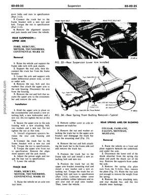 101
101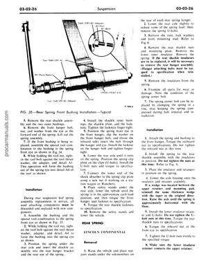 102
102 103
103 104
104 105
105 106
106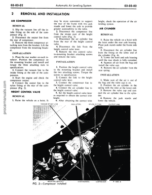 107
107 108
108 109
109 110
110 111
111 112
112 113
113 114
114 115
115 116
116 117
117 118
118 119
119 120
120 121
121 122
122 123
123 124
124 125
125 126
126 127
127 128
128 129
129 130
130 131
131 132
132 133
133 134
134 135
135 136
136 137
137 138
138 139
139 140
140 141
141 142
142 143
143 144
144 145
145 146
146 147
147 148
148 149
149 150
150 151
151 152
152 153
153 154
154 155
155 156
156 157
157 158
158 159
159 160
160 161
161 162
162 163
163 164
164 165
165 166
166 167
167 168
168 169
169 170
170 171
171 172
172 173
173 174
174 175
175 176
176 177
177 178
178 179
179 180
180 181
181 182
182 183
183 184
184 185
185 186
186 187
187 188
188 189
189 190
190 191
191 192
192 193
193 194
194 195
195 196
196 197
197 198
198 199
199 200
200 201
201 202
202 203
203 204
204 205
205 206
206 207
207 208
208 209
209 210
210 211
211 212
212 213
213 214
214 215
215 216
216 217
217 218
218 219
219 220
220 221
221 222
222 223
223 224
224 225
225 226
226 227
227 228
228 229
229 230
230 231
231 232
232 233
233 234
234 235
235 236
236 237
237 238
238 239
239 240
240 241
241 242
242 243
243 244
244 245
245 246
246 247
247 248
248 249
249 250
250 251
251 252
252 253
253 254
254 255
255 256
256 257
257 258
258 259
259 260
260 261
261 262
262 263
263 264
264 265
265 266
266 267
267 268
268 269
269 270
270 271
271 272
272 273
273 274
274 275
275 276
276 277
277 278
278 279
279 280
280 281
281 282
282 283
283 284
284 285
285 286
286 287
287 288
288 289
289 290
290 291
291 292
292 293
293 294
294 295
295 296
296 297
297 298
298 299
299 300
300 301
301 302
302 303
303 304
304 305
305 306
306 307
307 308
308 309
309 310
310 311
311 312
312 313
313 314
314 315
315 316
316 317
317 318
318 319
319 320
320 321
321 322
322 323
323 324
324 325
325 326
326 327
327 328
328 329
329 330
330 331
331 332
332 333
333 334
334 335
335 336
336 337
337 338
338 339
339 340
340 341
341 342
342 343
343 344
344 345
345 346
346 347
347 348
348 349
349 350
350 351
351 352
352 353
353 354
354 355
355 356
356 357
357 358
358 359
359 360
360 361
361 362
362 363
363 364
364 365
365 366
366 367
367 368
368 369
369 370
370 371
371 372
372 373
373 374
374 375
375 376
376 377
377 378
378 379
379 380
380 381
381 382
382 383
383 384
384 385
385 386
386 387
387 388
388 389
389 390
390 391
391 392
392 393
393 394
394 395
395 396
396 397
397 398
398 399
399 400
400 401
401 402
402 403
403 404
404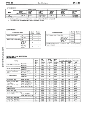 405
405 406
406 407
407 408
408 409
409 410
410 411
411 412
412