Page 105 of 413
03-02-29
Suspension
03-02-29
SPRING LEAVES
AND TIE-BOLT
LINCOLN CONTINENTAL
Check for broken spring leaves. In-
spect the anti-squeak inserts between
the leaves, and replace them if they
are worn. The spring leaves must be
dry and free of oil and dirt before new
inserts are installed.
If the spring center tie-bolt requires
replacement, clamp the spring in a
vise to keep the spring compressed
during bolt removal and installation.
REAR SHACKLE AND
HANGER ASSEMBLY
LINCOLN CONTINENTAL
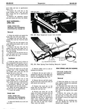
Inspect the rear shackle, bushings,
and studs for wear or damage. Re-
place parts where necessary (Fig. 6).
If the rear shackle bushings are to
be replaced, it will be necessary to re-
move the rear hanger assembly. Tor-
que the hanger attaching bolts to
specification when installed.procarmanuals.com
Page 106 of 413

03-03-01
Automatic
Air
Leveling System
03-03-01
PART
3-3
Automatic
Air
Leveling System
COMPONENT INDEX
AIR COMPRESSOR
Disassembly
and
Overhaul
Removal
and
Installation
AIR CYLINDER
Removal
and
Installation
DESCRIPTION
HEIGHT CONTROL VALVE
Disassembly
and
Overhaul
Removal
and
Installation
MODEL APPLICATION
All
Models
Ford
03-03
03-02
03-02
03-01
03-03
03-02
Mercury
03-03
03-02
03-02
03-01
03-03
03-02
Meteor
03-03
03-02
03-02
03-01
03-03
03-02
Cougar
N/A
N/A
N/A
N/A
N/A
N/A
Fairlane
N/A
N/A
N/A
N/A
N/A
N/A
A page number indicates that the item
is for the
vehicle listed
at
the head
of
the column.
N/A indicates that
the
item
is not
applicable
to the
vehicle listed.
Falcon
N/A
N/A
N/A
N/A
N/A
N/A
Montego
N/A
N/A
N/A
N/A
N/A
N/A
Mustang
N/A
N/A
N/A
N/A
N/A
N/A
Lincoln-
Continental
N/A
N/A
N/A
N/A
N/A
N/A
Thunderbird
N/A
N/A
N/A
N/A
N/A
N/A
Continental-
Mark III
N/A
N/A
N/A
N/A
N/A
N/A
DESCRIPTION
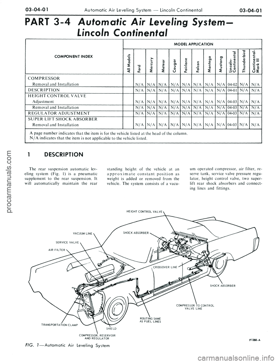
The automatic level control
is an
accessory item
on the
Ford, Mercury
and Meteor vehicles
(Fig. 1).
This
de-
vice
is a
supplement
to the
rear coil
spring suspension,
and
will automati-
cally maintain
the
rear standing height
of
the
vehicle
at an
approximate
con-
stant position compensating
for
vary-
ing loaded conditions.
The
system
consists
of a
vacuum operated
com-
pressor, control valve,
air
cylinders
and
the
connecting lines
and
fittings.
In
the
event
of
accidental
air
loss,
the
conventional coil springs will support
the vehicle.
RUBBER
AIR
CYLINDER
WITHIN COIL SPRING
HEIGHT CONTROL
VALVE
RUBBER
AIR
CYLINDER
WITHIN COIL SPRING
RUBBER VACUUM LINE
TO
VACUUM
DISTRIBUTION CONNECTOR
RED CLAMP STATION WAGON ONLY
COMPRESSOR
NYLON
AND
STEEL LINES
FROM VALVE
TO
CYLINDERS
FIG.
1
—
Air Leveling System
FT475-A
procarmanuals.com
Page 107 of 413

03-03-02
Automatic Air Leveling System
03-03-02
REMOVAL AND INSTALLATION
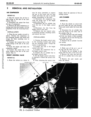
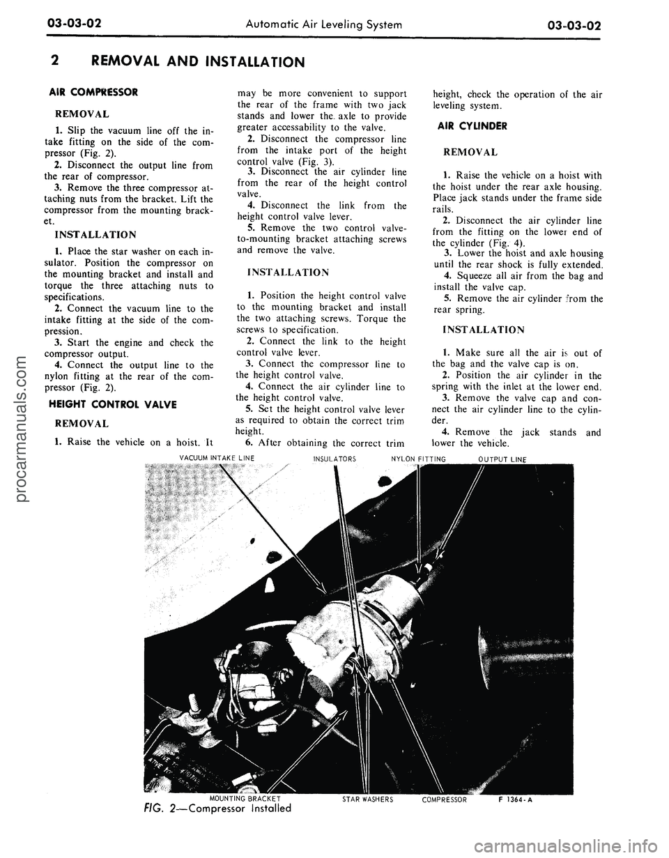
AIR COMPRESSOR
REMOVAL
1.
Slip the vacuum line off the in-
take fitting on the side of the com-
pressor (Fig. 2).
2.
Disconnect the output line from
the rear of compressor.
3.
Remove the three compressor at-
taching nuts from the bracket. Lift the
compressor from the mounting brack-
et.
INSTALLATION
1.
Place the star washer on each in-
sulator. Position the compressor on
the mounting bracket and install and
torque the three attaching nuts to
specifications.
2.
Connect the vacuum line to the
intake fitting at the side of the com-
pression.
3.
Start the engine and check the
compressor output.
4.
Connect the output line to the
nylon fitting at the rear of the com-
pressor (Fig. 2).
HEIGHT CONTROL VALVE
REMOVAL
1.
Raise the vehicle on a hoist. It
may be more convenient to support
the rear of the frame with two jack
stands and lower the, axle to provide
greater accessability to the valve.
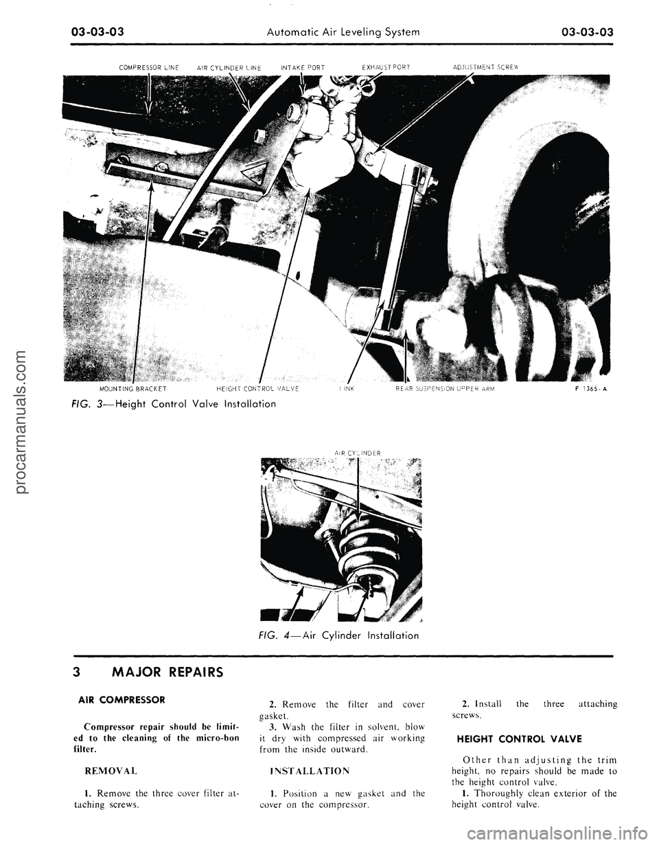
2.
Disconnect the compressor line
from the intake port of the height
control valve (Fig. 3).
3.
Disconnect the air cylinder line
from the rear of the height control
valve.
4.
Disconnect the link from the
height control valve lever.
5.
Remove the two control valve-
to-mounting bracket attaching screws
and remove the valve.
INSTALLATION
1.
Position the height control valve
to the mounting bracket and install
the two attaching screws. Torque the
screws to specification.
2.
Connect the link to the height
control valve lever.
3.
Connect the compressor line to
the height control valve.
4.
Connect the air cylinder line to
the height control valve.
5.
Set the height control valve lever
as required to obtain the correct trim
height.
6. After obtaining the correct trim
height, check the operation of the air
leveling system.
AIR CYLINDER
REMOVAL
1.
Raise the vehicle on a hoist with
the hoist under the rear axle housing.
Place jack stands under the frame side
rails.
2.
Disconnect the air cylinder line
from the fitting on the lower end of
the cylinder (Fig. 4).
3.
Lower the hoist and axle housing
until the rear shock is fully extended.
4.
Squeeze all air from the bag and
install the valve cap.
5.
Remove the air cylinder from the
rear spring.
INSTALLATION
1.
Make sure all the air is out of
the bag and the valve cap is on.
2.
Position the air cylinder in the
spring with the inlet at the lower end.
3.
Remove the valve cap and con-
nect the air cylinder line to the cylin-
der.
4.
Remove the jack stands and
lower the vehicle.
VACUUM INTAKE LINE
INSULATORS
NYLON FITTING
MOUNTING BRACKET
FIG. 2—Compressor Installed
STAR WASHERS
COMPRESSOR
F 1364-Aprocarmanuals.com
Page 108 of 413
03-03-03
Automatic Air Leveling System
03-03-03
COMPRESSOR LINE
AIR
CYLINDER LINE INTAKE PORT EXHAUSTPORT
ADJUSTMENT SCREW
MOUNTING BRACKET
HEIGHT CONTROL VALVE
REAR SUSPENSION UPPER
ARM
FIG. 3—Height Control Valve Installation
Al R CYLINDER
F 1365-A
FIG. 4—Air Cylinder Installation
3 MAJOR REPAIRS
AIR COMPRESSOR
Compressor repair should
be
limit-
ed
to the
cleaning
of the
micro-bon
filter.
REMOVAL
1.
Remove
the
three cover filter
at-
taching screws.
2.
Remove
the
filter
and
cover
gasket.
3.
Wash
the
filter
in
solvent, blow
it
dry
with compressed
air
working
from
the
inside outward.
INSTALLATION
1.
Position
a new
gasket
and the
cover
on the
compressor.
2.
Install
the
three attaching
screws.
HEIGHT CONTROL VALVE
Other than adjusting
the
trim
height,
no
repairs should
be
made
to
the height control valve.
1.
Thoroughly clean exterior
of the
height control valve.procarmanuals.com
Page 109 of 413
Page 110 of 413
Page 111 of 413

03-04-02
Automatic Air Leveling System — Lincoln Continental
03-04-02
REMOVAL AND INSTALLATION
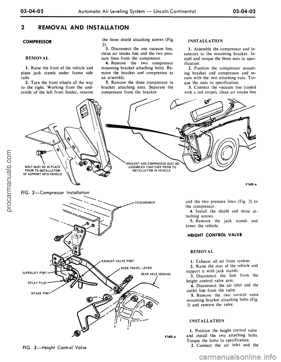
COMPRESSOR
REMOVAL
1.
Raise the front of the vehicle and
place jack stands under frame side
rails.
2.
Turn the front wheels all the way
to the right. Working from the und-
erside of the left front fender, remove
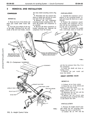
the three shield attaching screws (Fig.
2).
3.
Disconnect the one vacuum line,
clean air intake line and the two pres-
sure lines from the compressor.
4.
Remove the two compressor
mounting bracket attaching bolts. Re-
move the bracket and compressor as
an assembly.
5.
Remove the three compressor to
bracket attaching nuts. Separate the
compressor from the bracket.
INSTALLATION
1.
Assemble the compressor and in-
sulators to the mounting bracket. In-
stall and torque the three nuts to spec-
ification.
2.
Position the compressor mount-
ing bracket and compressor and se-
cure with the two attaching nuts. Tor-
que the nuts to specification.
3.
Connect the vacuum line (coded
with a red stripe), clean air intake line
BRACKET
AND
COMPRESSOR
MUST
BE
ASSEMBLED
TOGETHER
PRIOR
TO
INSTALLATION
IN
VEHICLE
BOLT MUST
BE IN
PLACE
PRIOR
TO
INSTALLATION
OF
SUPPORT
INTO
VEHICLE
FIG. 2—Compressor Installation
CROSSMEMBER
EXHAUST
VALVE PORT
OVER
TRAVEL
LEVER
REAR AXLE
HOUSING
F1400-A
3—Height Control Valve
F1420-A
and the two pressure lines (Fig. 2) to
the compressor.
4.
Install the shield and three at-
taching screws.
5.
Remove the jack stands and
lower the vehicle.
HEIGHT CONTROL VALVE
REMOVAL
1.
Exhaust all air from system.
2.
Raise the rear of the vehicle and
support it with jack stands.
3.
Disconnect the link from the
height control valve arm.
4.
Disconnect the air inlet and the
outlet line from the valve.
5.
Remove the two control valve
mounting bracket attaching bolts (Fig.
3) and remove the valve.
INSTALLATION
1.
Position the height control valve
and install the two attaching bolts.
Torque the bolts to specification.
2.
Connect the air inlet and theprocarmanuals.com
Page 112 of 413

03-04-03
Automatic Air Leveling System — Lincoln Continental
03-04-03
outlet lines to their respective parts.
3.
Adjust the trim height as de-
tailed in Section 4.
4.
Connect the link to the arm.
5.
Remove the jack stands and
lower the vehicle.
SUPER LIFT SHOCK ABSORBER
REMOVAL
1.
Raise the vehicle and place jack
stands under the axle to compress the
super lift.
2.
Loosen the air line or lines (right
super lift) slowly to release the air
from the system. Then, disconnect the
line or lines.
3.
Remove the three mounting plate
attaching screws from the upper end
of the super lift.
4.
Remove the attaching nut and
washer from the lower end of the
super lift and remove it from the vehi-
cle.
5.
Remove the nut, outer washer
and the insulator that attach the super
lift to the mounting plate. Remove the
plate, remaining insulator and washer.
INSTALLATION
1.
Position a washer, insulator,
mounting plate, insulator, washer and
nut on the stud at the upper end of
the super lift. Torque the nut to speci-
fication.
2.
Install the mounting plate, outer
insulator, washer and nut on the stud.
Torque the nut to specification.
3.
Attach the mounting plate and
shock absorber to the crossmember
with the attaching screws to specifica-
tions.
4.
Connect the lower end of the
super lift to the mounting stud with
the washers and attaching nut. Torque
the nut to specification.
5.
Connect the air line or lines
(right super lift) to the super lift.
6. Start the engine and check for
leaks.
3 IN-VEHICLE ADJUSTMENTS AND REPAIRS
REGULATOR ADJUSTMENT HEIGHT CONTROL VALVE
The regulator may be adjusted if
the regulator pressure is under 100 psi
with the reservoir pressure at a mini-
mum of 140 psi. If the regulated pres-
sure exceeds 130 psi, the regulator
must be replaced.
To adjust the regulator, remove the
boot and reposition the sleeve and re-
tainer deeper into the body of the re-
gulator, using a deep well socket (Fig.
4).
If the regulator pressure remains
under 100 psi, replace regulator.
SILICONE FLUID
REPLACEMENT
If the height control valve time
delay does not fall within specifica-
tion, the silicone fluid must be re-
placed. Then repeat the time delay
test. If delay is still not within specifi-
cations, replace the height control
valve.
1.
Remove control valve and clean
the exterior of the valve thoroughly.
2.
Position the valve with delay
plug on top. Remove delay plug and
drain silicone fluid from the chamber.
Remove the O-ring from the chamber
(Fig. 5), and discard the O-ring.
3.
Remove the cover plate retaining
ring, using snap ring pliers. Remove
the delay cover from the valve body.
Remove the O-ring from the chamber,
and discard the O-ring.
4.
Place a new O-ring over the
delay plug and install the plug. Tor-
que the plug to 20-30 in-lbs. .
5.
Pour silicone fluid into the delay
piston chamber until fluid level is 5/16
inch below the top edge of the body.
Add or remove fluid with an eye drop-
per until the proper fluid level is
reached.
6. Hold the control valve body in a
vise with the delay chamber elevated
slightly. Carefully operate the lever to
purge trapped air from the fluid.
7.
Place a new O-ring in the groove
around the delay piston bore. Install
5/16" TO
FLUID LEVEL
F 1405 A
FIG. 4—Adjusting Regulator
F1406 A
FIG. 5—Replacing Silicone Fluidprocarmanuals.com