Page 201 of 413

04-02-04
Rear Axle — Removable Carrier Type
04-02-04
IN-VEHICLE ADJUSTMENTS AND REPAIRS
REAR AXLE SHAFT, WHEEL
BEARING AND OIL SEAL
REPLACEMENT
The rear axle shafts, wheel bear-
ings,
and oil seal can be replaced
without removing the differential as-
sembly from the axle housing.
REMOVAL OF
AXLE SHAFT
Synthetic wheel bearing seals are
used in production only. Removal and
insertion of rear axle shafts must be
performed with caution. The entire
length of the shaft (including spline)
up to the seal journal must pass
through the seal without cutting of the
seal element during axle removal or
installation will result in early seal fai-
lure.
Leather seals only will be used as
service replacement for synthetic
wheel bearing seals.
1.
Remove the wheel cover, wheel
and tire from the brake drum.
2.
Remove the nuts that secure the
brake drum to the axle shaft flange,
then remove the drum from flange.
3.
Working through the hole pro-
vided in each axle shaft flange, re-
move the nuts that secure the wheel
bearing retainer plate. Then pull the
axle shaft assembly out of the axle
housing (Fig. 4). The brake backing
plate must not be dislodged. Install
one nut to hold the plate in place after
the axle shaft is removed.
Too/-4235-C
E1032-D
FIG. 4—Removing Axle Shaft
REMOVAL OF REAR
WHEEL BEARING AND
SEAL
Synthetic seals must not be cleaned,
soaked or washed in cleaning solvents.
Removal of the wheel bearings from
the axle shaft makes them unfit for
further use.
1.
On all models except Ford, Mer-
cury or Meteor, if the rear wheel
bearing is to be replaced, loosen the
inner retainer ring by nicking it deeply
with a cold chisel in several places
(Fig. 5). It will then slide off easily.
E 1731-A
FIG. 5—Removing Rear Wheel
Bearing Retainer Ring
On Ford, Mercury and Meteor mo-
dels,
it is necessary to first drill a 1/4
inch hole not more than 5/16 inch
deep in the retainer ring surface bef-
ore using the cold chisel.
2.
Remove the bearing from the
axle shaft with the tool shown in Fig.
6 or Fig. 7.
3.
Whenever a rear axle shaft is re-
placed, the oil seal must be replaced.
Remove the seal with Tool 1175-AB
and a slide hammer (Fig. 8). If new
leather-type wheel bearing service
seals are to be installed, soak new oil
seals in SAE 10 oil for 1/2 hour
before installing.
INSTALLATION OF REAR
WHEEL BEARING AND
SEAL
1.
Inspect the machined surface of
the axle shaft and the axle housing for
rough spots or other irregularities
which would affect the sealing action
of the oil seal. Check the axle shaft
splines for burrs, wear or twist. Care-
fully remove any burrs or rough spots.
Replace worn or damaged parts.
2.
Lightly coat wheel bearing bores
with axle lubricant.
3.
Place the retainer plate on the
axle shaft, and press the new wheel
bearing on the shaft with the tool
shown in Fig. 6 or Fig. 9. Do not at-
tempt to press on both the bearing
and the inner retainer ring at the same
time.
4.
Using the bearing installation
tool (Tool 4621-A or 4234-4), press
the bearing inner retainer ring on the
shaft until the retainer seats firmly
against the bearing. On Ford, Mercu-
ry, or Meteor models, before assem-
bling the retainer onto the axle shaft,
the shaft journal and the inside di-
ameter of the retainer should be wiped
clean with a dry cloth. These parts
must not be degreased or lubricated.
5. Rear wheel oil seals with synthe-
tic sealing elements have been incor-
porated in production only. However,
leather seals only will be used as re-
placements for the synthetic sealing
elements. Install the new oil seal with
the tools shown in Figs. 10 and 12. Be
sure the new seal has been soaked in
SAE 10 oil for 1/2 hour before in-
stalling it. Wipe a small amount of oil
resistant sealer on the outer edge of
the seal before it is installed. Do not
put sealer on the sealing lip.
INSTALLATION OF
AXLE SHAFT
1.
Carefully slide the axle shaft into
the housing so that the rough forging
of the shaft will not damage the oil
seal. Start the axle splines into the
side gear, and push the shaft in until
the bearing bottoms in the housing.
2.
Install the bearing retainer plate
and the nuts that secure it. Torque the
nuts to specifications.
3.
Install the brake drum and the
drum attaching (Tinnerman) nuts.
4.
Install the wheel and tire on the
drum. Install the wheel cover.
DRIVE PINION OIL SEAL
REPLACEMENT
COLLAPSIBLE SPACER
Synthetic seals must not be cleaned,
soaked or washed in cleaning solvent.
The drive pinion oil seal can be re-
placed without removing the differen-
tial carrier assembly from the axle
housing.
1.
Raise the vehicle and install
safety stands. Remove both rear wheels
and brake drums.
2.
Make scribe marks on the drive
shaft end yoke and the axle U-joint
flange to insure proper position of the
drive shaft at assembly (Fig. 11). Dis-
connect the drive shaft from the axle
U-joint flange. Be careful to avoid
dropping the loose universal joint
bearing cups. Hold the cups on the
spider with tape. Mark the cups so
that they will be in their original posi-
tion in relation to the flange when
they are assembled. Remove the drive
shaft from the transmission extension
housing. Install an oil seal replacer
tool in the transmission extension
housing to prevent transmission fluidprocarmanuals.com
Page 202 of 413
04-02-05
Rear Axle
—
Removable Carrier Type
04-02-05
Bridge
Side Rail
_J f.
Detail 4
Tool-T60K-1225-A
Press
Ram
FOR
ADJUSTABLE
BED PRESS
Press
Ram
BEARING
'—
Support
Plat*
—*
BEARING INSTALLATION
VIEW
2
1
Support Plate
BEARING REMOVAL
VIEW
1
FOR FIXED
BED PRESS
Press
Ram
Press
Ram
BEARING
LSupport Flange^
BEARING REMOVAL
VIEW
3
Adapter Ring
1—
Support Plate
—»
BEARING INSTALLATION
VIEW
4
FOR
PUSH-PULLER
OPERATION
BEARING REMOVAL
VIEW
5
BEARING
BEARING
INSTALLATION
VIEW
6
E1269-B
FIG.
6—Removing
and
Installing Wheel Bearingprocarmanuals.com
Page 203 of 413

04-02-06
Rear Axle — Removable Carrier Type
04-02-06
FIG. 7—Removing Wheel Bearing
leakage. Refer to the transmission
group for the appropriate tool.
3.
Install an in-lb torque wrench on
the pinion nut. Record the torque re-
quired to maintain rotation of the pi-
nion shaft through several revolutions.
4.
Scribe the pinion shaft and the
U-joint flange inner surface for as-
sembly realignment. While holding the
flange with the tool shown in Fig. 22
or Fig. 23, remove the integral pinion
nut and washer.
5.
Clean the pinion bearing retainer
around the oil seal. PlaSe a drain pan
under the seal, or raise the front of
the vehicle higher than the rear.
6. Using the tool shown in Fig. 24
or Fig. 25, remove the U-joint flange.
7.
Using the tool shown in Fig. 26
remove the drive pinion oil seal.
8. Clean the oil seal seat.
9. Install the new seal in the retain-
er, using the applicable tool shown in
Fig. 47.
10.
Check splines on the pinion
shaft to be sure they are free of burrs.
If burrs are evident, remove them by
using a fine crocus cloth, working in a
rotational motion. Wipe the pinion
shaft clean.
11.
Apply a small amount of lubri-
cant to U-joint splines.
Align scribe marks on U-joint
flange and pinion shaft.
12.
Install the U-joint flange using
the tool shown in Fig. 46.
SCRIBE MARKS
AXLE SHAFT
FLANGE
Tool
4621-A
E1921A
FIG. 9—Installing Wheel Bearing
13.
Install a new integral nut and
washer on the pinion shaft. (Apply a
small amount of lubricant on the
washer side of the nut).
14.
Hold the flange with the tool
shown in Fig. 24 or Fig. 25 while
tightening nut.
15.
Tighten the pinion shaft nut,
rotating the pinion occasionally to in-
sure proper bearing seating, and take
frequent preload readings until the
preload is at the original recorded
reading established in step 3.
16.
After original preload has been
reached, tighten the pinion nut slowly,
until an additional preload of 8 to 14
in-lb over the original reading is
reached. The preload should not ex-
ceed 8 to 14 in-lb over the original
reading, or bearing failure may result.
Under no circumstances should the pi-
nion nut be backed off to lessen pre-
load. If this is done, a new pinion
bearing spacer must be installed. In
addition, the U-joint flange must
never be hammered on, or pneumatic
tools used.
17.
Remove the oil seal replacer
tool from the transmission extension
housing. Install the front end of the
drive shaft on the transmission output
shaft.
18.
Connect the rear end of the
drive shaft to the axle U-joint flange,
aligning the scribe marks made on the
Tool-1177
or 4245-B
E1359-A
U-BOLT-4529 2 REQ'D.
5/l<>-24
4 REQ'D.
12-15
LB.
FT.
IE 1783-A
FIG. 8—
Removing
Rear Wheel
Bearing Oil Seal
FIG. 70—Installing Rear Wheel
Bearing Oil Seal
FIG. 11
— Drive
Shaft-To-Axle
U-Joint Connection
drive shaft end yoke and the axle U-
joint flange (Fig. 11).
19.
Check the lubricant level Make
sure the axle is in running position.
Add whatever amount of specified lu-
bricant is required to reach the lower
edge of the filler plug hole.
SOLID SPACER
The drive pinion oil seal can be re-
placed without removing the differen-
tial carrier assembly from the axle
housing.
1.
Make scribe marks on the drive
shaft end yoke and the axle U-joint
flange to insure proper position of the
drive shaft at assembly (Fig. 11). Dis-
connect the drive shaft from the axle
U-joint flange. Be careful to avoid
dropping the loose universal joint
bearing cups. Hold the cups on the
spider with tape. Mark the cups so
that they will be in their original posi-
tion in relation to the flange when
they are assembled. Remove the drive
shaft from the transmission extension
housing to prevent transmission leak-
age.
Refer to the transmission group
for the appropriate tool.
2.
Make punch marks on the end
of the pinion shaft and the U-joint
flange inner surface for realignment.
While holding the flange with the tool
shown in Fig. 22 or Fig. 23, remove
the integral pinion nut and washer.
3.
Clean the pinion bearing retainer
around the oil seal. Place a drain pan
under the seal, or raise the front of
the vehicle higher than the rear.
4.
Using the tool shown in Fig. 24
or Fig. 23, remove the U-joint flange.
5.
Using the tool shown in Fig. 26
remove the drive pinion oil seal.
6. Clean the oil seal seat.
7.
Install the new seal in the retain-
er, using the applicable tool shown in
Fig. 47.
8. Check splines on the pinion shaft
to be sure they are free of burrs. Ifprocarmanuals.com
Page 204 of 413

04-02-07
Rear Axle — Removable Carrier Type
04-02-07
burrs are evident, remove them with a
fine crocus cloth, working in a rota-
tional motion, then wipe clean. Apply
a small quantity of lubricant to U-
joint splines.
9. Install the U-joint flange using
the tool shown in Fig. 46.
10.
Install a new integral attaching
nut and washer on the pinion shaft.
11.
Tighten the pinion attaching
nut, rotating the pinion several times
to seat the bearing, then torque the pin-
ion nut to 180-200 ft-lbs. Hold the
flange with the tool shown in Fig. 22
or Fig. 23 while the nut is being tight-
ened.
12.
Remove the oil seal replacer
tool from the transmission extension
housing. Install the front end of the
drive shaft on the transmission output
shaft.
13.
Connect the rear end of the
drive shaft to the axle U-joint flange,
aligning the scribe marks made on the
drive shaft end yoke and the axle U-
joint flange.
14.
Check the lubricant level, and
add whatever amount of specified lu-
bricant is necessary to reach the lower
edge of the filler plug hole. Make sure
the axle is in running position when
the level is checked
ORIGINAL U-JOINT FLANGE
(IN VEHICLE REPLACEMENT)
Use procedure as outlined under
Drive Pinion Oil Seal Replacement.
Synthetic seals must not be cleaned,
soaked or washed in cleaning solvent.
INSTALLATION OF A NEW
UNIVERSAL JOINT FLANGE
COLLAPSIBLE SPACER
1.
Raise the vehicle and install
safety stands. Remove both rear wheels
and brake drums.
2.
Disconnect the drive shaft from
the axle U-joint flange. Be careful to
avoid dropping the loose universal
joint bearing cups. Hold the cups on
the spider with tape. Mark the cups so
that they will be in their original posi-
tion in relation to the flange when
they are assembled. Remove the drive
shaft from the transmission extension
housing. Install an oil seal replacer
tool in the transmission extension
housing to prevent transmission fluid
leakage. Refer to the transmission
group for the appropriate tool.
3.
Install an in-lb torque wrench on
the pinion nut. Record the torque re-
quired to maintain rotation of the pin-
ion shaft through several revolutions.
4.
While holding the flange with the
tool shown in Fig. 23 or Fig. 24, re-
move the integral pinion nut and
washer.
5.
Clean the pinion bearing retainer
around the oil seal. Place a drain pan
under the seal, or raise the front of
the vehicle higher than the rear. Syn-
thetic seals must not be cleaned,
soaked or washed in cleaning solvent.
6. Using the tool shown in Fig. 23
or Fig. 24, remove the U-joint flange.
7.
Check splines on the pinion shaft
to be sure they are free of burrs. If
burrs are evident, remove them by
using a fine crocus cloth, working in a
rotational motion, then wipe clean.
Apply a small amount of lubricant
to U-joint splines.
8. Install the U-joint flange using
the tool shown in Fig. 46.
9. Install a new integral nut and
washer on the pinion shaft. (Apply a
small amount of lubricant on the
washer side of the nut.)
10.
Hold the flange with the tool
shown in Fig. 23 or Fig. 24 while the
nut is being tightened.
11.
Tighten the pinion shaft nut,
rotating the pinion occasionally to in-
sure proper bearing seating, and take
frequent preload readings until the
preload is at the original recorded
reading established in step 3.
12.
After original preload has been
reached, tighten the pinion nut slowly,
until an additional preload of 8 to 14
in-lb over the original reading is
reached. (The preload should not ex-
ceed 8 to 14 in-lb over the original
reading, or bearing failure may result.
Under no circumstances should the
pinion nut be backed off to lessen pre-
load. If this is done, a new pinion
bearing spacer must be installed. In
addition, the U-joint flange must
never be hammered on, or power tools
used.
13.
Remove the oil seal replacer
tool from the transmission extension
housing. Install the front end of the
drive shaft on the transmission output
shaft.
14.
Connect the rear end of the
drive shaft to the axle U-joint flange,
aligning the scribe marks made on the
drive shaft end yoke and the axle U-
joint flange.
15.
Check the lubricant level. Make
sure the axle is in running position.
Add whatever amount of specified lu-
bricant is required to reach the lower
edge of the filler plug hole.
SOLID SPACER
1.
Disconnect the drive shaft from
the axle U-joint flange. Be careful to
avoid dropping the loose universal
joint bearing cups. Hold the cups on
the spider with tape. Mark the cups so
that they will be in their original posi-
tion in relation to the flange when
they are assembled. Remove the drive
shaft from the transmission extension
housing. Install an oil seal replacer
tool in the transmission extension
housing to prevent transmission leak-
age.
Refer to the transmission group
for the appropriate tool.
2.
While holding the flange with the
tool shown in Fig. 23 or Fig. 24, re-
move the integral pinion nut and
washer.
3.
Clean the pinion bearing retainer
around the oil seal. Place a drain pan
under the seal, or raise the front of
the vehicle higher than the rear.
4.
Using the tool shown in Fig. 23
or Fig. 24, remove the U-joint flange.
5.
Check splines on the pinion shaft
to be sure they are free of burrs. If
burrs are evident, remove them by
using a fine crocus cloth, working in a
rotational motion, then wipe clean.
Apply a small amount of lubricant to
U-joint splines.
6. Install the U-joint flange using
the tool shown in Fig. 46.
7.
Install integral attaching nut and
washer on the pinion shaft.
8. Tighten the pinion attaching nut,
rotating the pinion several times to
seat the bearing, then torque the pin-
ion attaching nut to 180-220 ft-lbs.
Hold the flange with the tool shown in
Fig. 23 or Fig. 24 while the nut is
being tightened.
9. Remove the oil seal replacer tool
from the transmission extension hous-
ing. Install the front end of the drive
shaft on the transmission output shaft.
10.
Connect the rear end of the
drive shaft to the axle U-joint flange.
11.
Check the lubricant level, and
add whatever amount of specified lu-
bricant is necessary to reach the lower
edge of the filler plug hole. Make sure
the axle is in running position when
the level is checked.
DRIVE SHAFT PINION ANGLE
ADJUSTMENT
Refer to Group 3, Part 3-2 for this
procedure.procarmanuals.com
Page 205 of 413

04-02-08
Rear Axle — Removable Carrier Type
04-02-08
REMOVAL AND INSTALLATION
CARRIER ASSEMBLY
REMOVAL
1.
Raise the vehicle on a hoist and
remove the two rear wheels and tires.
2.
Remove the two brake drums (3
Tinnerman nuts at each drum) from
the axle shaft flange studs. If diffi-
culty is experienced in removing the
drums, remove the brake adjuster
knockout slug or rubber plug (if so
equipped) and back off the brake
shoes.
3.
Working through the hole pro-
vided in each axle shaft flange, re-
move the nuts that secure the rear
wheel bearing retainer plate. Pull each
axle shaft assembly out of the axle
housing using axle shaft remover,
Tool 4235-C. (Fig. 4). Care must be
exercised to prevent damage to the
production-type synthetic oil seal, if so
equipped. Any roughing or cutting of
the seal element during removal or in-
stallation can result in early seal fail-
ure.
Install a nut on one of the brake
backing plate attaching bolts to hold
the plate to the axle housing after the
shaft has been removed. Whenever a
rear axle shaft is replaced, the wheel
bearing oil seals must be replaced.
Remove the seals with tool 1175AB.
4.
Make scribe marks on the drive
shaft end yoke and the axle U-joint
flange to insure proper position at as-
sembly. Disconnect the drive shaft at
the rear axle U-joint. Hold the cups
on the spider with tape. Mark the
cups so that they will be in their orig-
inal position relative to the flange
when they are assembled. Remove the
drive shaft from the transmission ex-
tension housing. Install an oil seal re-
placer tool in the housing to prevent
transmission leakage. Refer to the
transmission group for the appropriate
tool.
5.
Clean area around carrier to
housing surfaced with a wire brush and
wipe clean, to prevent dirt entry into
the housing. Place a drain pan under
the carrier and housing, remove the
carrier attaching nuts, and drain the
axle.
Remove the carrier assembly
from the axle housing.
INSTALLATION
Synthetic production-type wheel
bearing seals must not be cleaned,
soaked or washed in cleaning solvent.
1.
Clean the axle housing and
shafts using kerosene and swabs. To
avoid contamination of the grease in
the sealed ball bearings, do not allow
any quantity of solvent directly on the
wheel bearings. Clean the mating sur-
faces of the axle housing and carrier.
2.
Position the differential carrier
on the studs in the axle housing using
a new gasket between carrier and
housing. Install the carrier-to-housing
attaching nuts, and torque them to
specifications.
3.
Remove the oil seal replacer tool
from the transmission extension hous-
ing. Position the drive shaft so that
the front U-joint slip yoke splines to
the transmission output shaft.
4.
Connect the drive shaft to the
axle U-joint flange, aligning the scribe
marks made on the drive shaft end
yoke and the axle U-joint flange dur-
ing the removal procedure. Install the
U-bolts and nuts and torque to speci-
fications.
5.
If the synthetic, production-type
wheel bearing seals were replaced with
service-type leather seals, soak the
new rear wheel bearing oil seals in
SAE 10 oil for 1/2 hour before instal-
lation. Wipe a small amount of an oil
resistant sealer on the outer edge of
each seal before it is installed. Do not
put any of the sealer on the sealing
lip.
Install the oil seals in the ends of
the rear axle housing with one of the
tools shown in Figs. 10 and 12.
Tool
T65F-1177.A
E 1571-A
FIG. 12—Rear Axle Shaft Bearing
Seal Installation
6. Install the two axle shaft assem-
blies in the axle housing. Care must
be exercised to prevent damage to the
oil seals. The shorter shaft goes into
the left side of the housing.
Carefully slide the axle shaft into
the housing so that the rough forging
of the shaft will not damage the oil
seal. Start the axle splines into the
differential side gear, and push the
shaft in until the bearing bottoms in
the housing.
7.
Install the bearing retainers on
the attaching bolts on the axle housing
flanges. Install the nuts on the bolts
and torque to specifications.
8. If the rear brake shoes were
backed off, adjust the brakes as out-
lined in Part 2-1 and install rubber
plugs in the adjuster slots.
9. Install the two rear brake drums
and the drum Tinnerman nuts.
10.
Install the rear wheels and tires.
11.
Fill the rear axle with specified
lubricant.
AXLE HOUSING (COIL
SPRING SUSPENSION)
REMOVAL
1.
Remove the carrier assembly
from the axle housing as outlined in
Differential Carrier Removal and In-
stallation.
2.
Position safety stands under the
frame rear members, and support the
axle housing with either a floor jack
or hoist.
3.
Disengage the brake line from
the clips that retain the line to the
axle housing.
4.
Disconnect the vent tube from
the rear axle housing.
5.
Remove the brake backing plate
assemblies from the axle housing, and
support them with wire. Do not dis-
connect the brake line.
6. Disconnect the lower studs of the
two rear shock absorbers from the
mounting brackets on the axle housing
(Fig. 13 and 14).
7.
Remove the attaching nut and
washer, and disconnect the track bar
from the mounting stud on the axle
housing bracket.
8. Lower the axle housing until the
coil springs are released. Lift out the
coil springs and insulators.
9. Remove the nuts, washers and
pivot bolts that connect the suspension
lower arms to the axle housing. Dis-
connect both arms from the axle
housing.
10.
Disconnect the upper suspen-
sion arm from the axle housing by re-
moving the pivot bolt, nut, lock wash-
er and the two eccentric washers (Fig.
13 and 14).
11.
Lower the axle housing and re-
move it from under the vehicle.
INSTALLATION
1.
Transfer the track bar mounting
stud from the old to the new housing.procarmanuals.com
Page 206 of 413
REAR SPRING
5560
VENT
TUBE
INDENT TOWARD
FRONT OF VEHICLE
UPPER ARM
5500
LEFT ARM INDENTED
BY 2 NOTCHES IN BUSHING FLANGE
F 1353-A
f/Q.
J3—Rear Axle Installation—Typical Coil Spring Suspensionprocarmanuals.com
Page 207 of 413

• NUT-55754-S7
9/16-12
60-85 LB. FT.
4002 (2 REQUIRED)
• BOLT-304907-S2
9/16-12
80-105 LB. FT.
NO.
4 CROSSMEMBER-")
NUT-33847-S8
9/16-12
100-130 LB FT.
*-34785-S7
-CAM-5A637 (2 REQUIRED)
• NUT-55754-S7
9/16-12
60-85 LB. FT.
4002 (2 REQUIRED)
• BOLT-304907-S2
9/16-12
80-105 LB. FT.
NO.
4 CROSSMEMBER-5029
VENT TUBE-4A001
NUT-34664-S
3/8-24
(2 REQUIRED)
15-25 LB. FT.
WASHER-18041
(2 REQUIRED)
BOLT-559bl-S2
(2 REQUIRED)
TRACK BAR STUD-4269
•110-140 LB. FT.
VENT-4338
VENT MUST POINT
TO THE REAR
CLIP-374998-S100
BUMPER ASSEMBLY-4906
BUSHING-500939
(4 REQUIRED)
WASHER-18171
(2 REQUIRED)
BOLT-40923-S2
(2 REQUIRED)
BOLT-39883-S8
(4 REQUIRED)
9-13 LB. FT.
NUT-33847-
9/16-12*100-130
LB. FT
L
OC
KWASHE R -34
785
-S 7
BACKING PLATE
ASSEMBLY
*2290 R.H. #2210 L.H.
REAR AXLE ASSEMBLY
4001 REFERENCE
TRACK BAR AND
BUSHING ASSEMBLY-5A639
NUT-55754-S7
9/16-12
80-105 LB. FT.
TRACK BAR AND
oJSHfNG ASSEMBLY
5A639
PARKING BRAKE
CABLE »2A635 R.H
•2A809 L.H.
(2 REQUIRED)
SHOCK ABSORBER-18080'
REFERENCE (2 REQUIRED)
•BOLT-2248
(8 REQUIRED)
• SEAL-2256
(2 REQUIRED)
PRONGS MUST BE SECURELY
LOCKED IN PLACE
WHEEL-1007
(2 REQUIRED)
INSULATOR-5536
(4 REQUIRED)
TIRE VALVE-1700
(2 REQUIRED
TIRE VALVE
XTENSION-1705©
(2 REQUIRED)
FRAME ASSEMBLY-5005
LOWER ARM-5A648
DRIVE SHAFT ASSEMBLY-4602
SPRING-5560
(2 REQUIRED)
• NUT-34447-S8
7/16-20
(8 REQUIRED)
30-45 LB. FT.
•BRAKE DRUM-1126
(2 REQUIRED)
TIRE-1508
(2 REQUIRED)
• NUT-372188-S32 (6 REQUIRED)
ASSEMBLE NUTS TO HOLD DRUM ASSEMBLY
SECURELY AGAINST FLANGE
BOLT-379334-S8
9/16-12
(2 REQUIRED)
NUT-375022-S2
70-90 LB. FT. NUT
90-120 LB. FT. BOLT
NUT-375022-S2
(2 REQUIRED)
-90 LB. FT. NUT
90-120 LB. FT. BOLT
BOLT-3 79334-S8
(2 REQUIRED)
NUT-34988-S4
(4 REQUIRED)
44-52 LB. FT.
FRAME ASSEMBLY-5005
REFERENCE
2
o
i
O
TO
Q
>
X
TO
O
3
n
Q
©USE 1705 VALVE EXTENSION
WITH FULL WHEEL COVERS
* TORQUE NUT OR BOLT
TORQUE NUT OR STUD
ITEMS MARKED •
PURCHASED AS PART OF
4001 REAR AXLE ASSEMBLY
NUT-375032-S36
1/2-23
(2 REQUIRED) 50-85 LB. FT.
SPRING MUST BE POSITIONED
AS SHOWN FOR R.H. SIDE
SPRING MUST BE POSITIONED
AS SHOWN FOR L.H. SiDE
NUT-375022-S2 (2 REQUIRED)
70-90 LB. FT. NUT
90-120 LB. FT. BOLTl
TIONAL
El 746-A
?
6
FIG. 14—Redr Axle Installation—Thunderbird—Typical Ford, Mercury, Meteor and Continental Markprocarmanuals.com
Page 208 of 413

04-02-11
Rear Axle — Removable Carrier Type
04-02-11
If the axle housing is new, install a
new vent. The hose attaching portion
must face toward the front of the ve-
hicle.
2.
If leather-type wheel bearing ser-
vice seals are to be installed, soak the
new rear wheel bearing oil seals in
SAE 10 oil for 1/2 hour before instal-
lation. Wipe a small amount of an oil
resistant sealer on the outer edge of
each seal before it is installed. Do not
put any of the sealer on the sealing
lip.
Install the oil seals in the ends of
the axle housing with one of the tools
shown in Fig. 10 and 12.
3.
Position the replacement axle
housing under the vehicle, and raise
the axle with a hoist or floor jack.
Connect the suspension lower arms to
their mounting brackets on the axle
housing with pivot bolts and nuts. Do
not tighten the bolts and nuts at this
point.
4.
Position the suspension upper
arm in its mounting bracket on the
axle housing, and install the adjusting
bolt, eccentric washers, lock washer
and nut. Leave the bolt and nut loose
at this point.
5.
Position the brake lines to the
axle housing, and secure with the re-
taining clips.
6. Install the brake backing plates
on the axle housing flanges.
7.
Connect the track bar to the
mounting stud, install the washer and
attaching nut, and torque to specifica-
tions.
8. Position the rear coil springs and
insulators in the pockets provided.
9. Connect the lower studs of the
two rear shock absorbers to the
mounting brackets on the axle hous-
ing. Install the attaching nuts, and
torque to specifications.
10.
Connect the vent tube to the
vent on the housing. If axle housing is
new, install a new vent.
11.
Clean the mating surfaces of
the axle housing and differential car-
rier. Position the carrier on the
mounting studs on the housing using a
new gasket between carrier and hous-
ing. Install the copper washers and the
carrier-to-housing attaching nuts, and
torque to specifications.
12.
Make sure that both the front
and rear pivot bolts of the upper and
the two lower arms are loose, and
then raise the axle assembly to con-
trolled curb height (Fig. 15). Hold the
axle at controlled curb height by plac-
ing blocks or pieces of steel pipe be-
tween the axle housing and the bumper
rear screw on the side rail. (See speci-
fications for dimensions.)
FRAME
TIGHTEN ARM
ATTACHING BOLTS
AT 5-45/64 INCH
HEIGHT POSITION
5-45/64 INCH
HEIGHT FOR
INSTALLATION
OF ARMS
E 1600-B
FIG. 75 -Axle Normal Curb
Height and Controlled Height
for Arm Installation
13.
With the axle at controlled curb
height, torque the suspension upper
and lower arm front pivot bolts and
nuts to specifications. Torque the
lower arm-to-axle housing pivot bolts
and nuts to specifications.
14.
Remove the oil seal replacer
tool from the transmission extension
housing. Position the drive shaft so
that the front U-joint slip yoke splines
to the transmission output shaft.
15.
Connect the drive shaft to the
U-joint flange, aligning the scribe
marks made on the drive shaft end
yoke and the axle U-joint flange dur-
ing the removal procedure. Install the
U-bolts and nuts and torque to speci-
fications.
16.
Carefully slide the two axle
shaft assemblies in the axle housing.
The shorter shaft goes into the left
side of the housing. Use care in slid-
ing the axle shafts into the housing so
that the rough forging of the shaft will
not damage the oil seal. Start the axle
splines into the differential side gear,
and push the shaft in until the rear
wheel bearing bottoms in the housing.
17.
Install the rear wheel bearing
retainers on the attaching bolts on the
axle housing flanges. Install the nuts
on the bolts and torque to specifica-
tions.
18.
If the rear brake shoes were
backed off, adjust the brakes as out-
lined in Part 2-1, and install rubber
plugs in the adjuster slots.
19.
Install the two rear brake
drums and the drum attaching (Tin-
nerman) nuts.
20.
Install the rear wheels and tires.
21.
Fill the rear axle to the bottom
of the filler plug hole located in either
the carrier casting or housing cover
with specified lubricant. Be sure that
the axle is in operating position.
22.
Road test the vehicle to be sure
that pinion and driveshaft angles are
correct. Any shudder during heavy ac-
celeration, or deceleration may require
a pinion and driveshaft angle re-
adjustment as detailed in Driveshaft
and Pinion Angle Adjustment, Group
3,
Part 3-2.
AXLE HOUSING (LEAF
SPRING SUSPENSION)
REMOVAL
1.
Raise the vehicle and support it
with safety stands under the rear
frame member.
2.
Drain the lubricant from the
axle.
3.
Make scribe marks on the drive
shaft end yoke and the axle U-joint
flange to insure proper position of the
drive shaft at assembly. Disconnect
the drive shaft at the drive pinion
flange.
4.
Disconnect the lower end of the
shock absorbers.
5.
Remove the wheels, brake drums
and both axle shafts as outlined in
Section 2.
6. Remove vent hose front vent
tube (Corbin clamp) and remove vent
tube from brake tube junction and
axle housing.
7.
Remove the hydraulic brake T-
fitting from the axle housing. Do not
open the hydraulic brake system lines.
Remove the hydraulic brake line from
its retaining clip on the axle housing.
8. Remove both axle shaft oil seals
with the tool shown in Fig. 8.
9. Remove both brake backing
plates from the axle housing and sus-
pend them above the housing with
mechanic's wire. The hydraulic brake
lines and the parking brake cables are
still attached to the brake backing
plates.
10.
Support the rear axle housing
on a jack, and then remove the spring
clip nuts. Remove the spring clip
plates (Fig. 16).
11.
Lower the axle housing and re-
move it from under the vehicle.
12.
If the axle housing is being re-
placed, transfer all the differential and
pinion parts to the new housing. See
Section 4, Major Repair Operation*.
INSTALLATION
1.
Raise the axle housing into posi-
tion so that the spring clip plates can
be installed. On a Montego or Fair-
lane,
position the spring upper insula-
tors and retainers between the axle
housing and springs and install theprocarmanuals.com
 1
1 2
2 3
3 4
4 5
5 6
6 7
7 8
8 9
9 10
10 11
11 12
12 13
13 14
14 15
15 16
16 17
17 18
18 19
19 20
20 21
21 22
22 23
23 24
24 25
25 26
26 27
27 28
28 29
29 30
30 31
31 32
32 33
33 34
34 35
35 36
36 37
37 38
38 39
39 40
40 41
41 42
42 43
43 44
44 45
45 46
46 47
47 48
48 49
49 50
50 51
51 52
52 53
53 54
54 55
55 56
56 57
57 58
58 59
59 60
60 61
61 62
62 63
63 64
64 65
65 66
66 67
67 68
68 69
69 70
70 71
71 72
72 73
73 74
74 75
75 76
76 77
77 78
78 79
79 80
80 81
81 82
82 83
83 84
84 85
85 86
86 87
87 88
88 89
89 90
90 91
91 92
92 93
93 94
94 95
95 96
96 97
97 98
98 99
99 100
100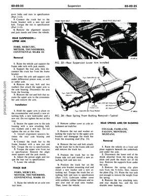 101
101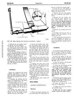 102
102 103
103 104
104 105
105 106
106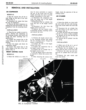 107
107 108
108 109
109 110
110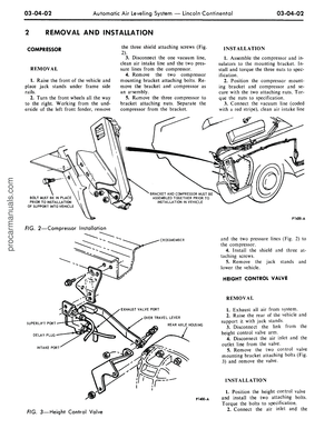 111
111 112
112 113
113 114
114 115
115 116
116 117
117 118
118 119
119 120
120 121
121 122
122 123
123 124
124 125
125 126
126 127
127 128
128 129
129 130
130 131
131 132
132 133
133 134
134 135
135 136
136 137
137 138
138 139
139 140
140 141
141 142
142 143
143 144
144 145
145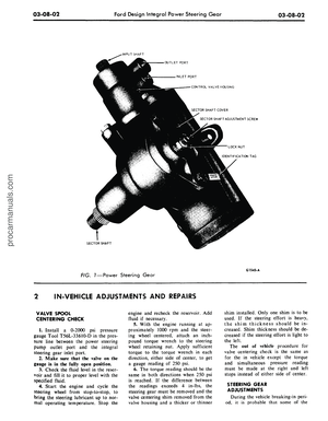 146
146 147
147 148
148 149
149 150
150 151
151 152
152 153
153 154
154 155
155 156
156 157
157 158
158 159
159 160
160 161
161 162
162 163
163 164
164 165
165 166
166 167
167 168
168 169
169 170
170 171
171 172
172 173
173 174
174 175
175 176
176 177
177 178
178 179
179 180
180 181
181 182
182 183
183 184
184 185
185 186
186 187
187 188
188 189
189 190
190 191
191 192
192 193
193 194
194 195
195 196
196 197
197 198
198 199
199 200
200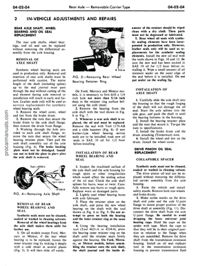 201
201 202
202 203
203 204
204 205
205 206
206 207
207 208
208 209
209 210
210 211
211 212
212 213
213 214
214 215
215 216
216 217
217 218
218 219
219 220
220 221
221 222
222 223
223 224
224 225
225 226
226 227
227 228
228 229
229 230
230 231
231 232
232 233
233 234
234 235
235 236
236 237
237 238
238 239
239 240
240 241
241 242
242 243
243 244
244 245
245 246
246 247
247 248
248 249
249 250
250 251
251 252
252 253
253 254
254 255
255 256
256 257
257 258
258 259
259 260
260 261
261 262
262 263
263 264
264 265
265 266
266 267
267 268
268 269
269 270
270 271
271 272
272 273
273 274
274 275
275 276
276 277
277 278
278 279
279 280
280 281
281 282
282 283
283 284
284 285
285 286
286 287
287 288
288 289
289 290
290 291
291 292
292 293
293 294
294 295
295 296
296 297
297 298
298 299
299 300
300 301
301 302
302 303
303 304
304 305
305 306
306 307
307 308
308 309
309 310
310 311
311 312
312 313
313 314
314 315
315 316
316 317
317 318
318 319
319 320
320 321
321 322
322 323
323 324
324 325
325 326
326 327
327 328
328 329
329 330
330 331
331 332
332 333
333 334
334 335
335 336
336 337
337 338
338 339
339 340
340 341
341 342
342 343
343 344
344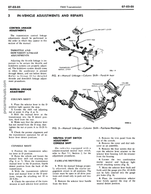 345
345 346
346 347
347 348
348 349
349 350
350 351
351 352
352 353
353 354
354 355
355 356
356 357
357 358
358 359
359 360
360 361
361 362
362 363
363 364
364 365
365 366
366 367
367 368
368 369
369 370
370 371
371 372
372 373
373 374
374 375
375 376
376 377
377 378
378 379
379 380
380 381
381 382
382 383
383 384
384 385
385 386
386 387
387 388
388 389
389 390
390 391
391 392
392 393
393 394
394 395
395 396
396 397
397 398
398 399
399 400
400 401
401 402
402 403
403 404
404 405
405 406
406 407
407 408
408 409
409 410
410 411
411 412
412
