Page 161 of 413

03-09-09
Saginaw Design Integral Power Steering Gear
03-09-09
Tool • T65P-3D517-A
LOCK NUT
ADJUSTER PLUG
G1628-A
FIG. 25
—
Adjusting Thrust Preload
end plug lightly with
a
soft-faced mal-
let
to
seat
it
properly.
19.
Snap
the
retainer ring
in
place
with
the
fingers.
Tap
lightly
on the
ring
to be
sure
the
ring
is
bottomed
securely
in the
housing.
20.
Turn
the
input shaft
to the
full
left
or
right position then turn
it
back
approximately
1 3/4
turns
to
center
the worm.
RACK PISTON
Tool - T65P.3805-A
FIG. 26—Installing Rack-Piston
21.
Place
an
in-lb torque wrench
on
the input shaft
as
shown
in Fig. 27.
22.
With
the
gear
on
center
and the
sector shaft adjuster backed
off,
meas-
ure
the
total drag. With
the
gear
on
center, adjust
the
sector shaft thrust
screw
so
that preload
is 4-8
in-lbs
in
excess
of
total preload
and
drag.
Readings
are to be
made through
an
arc
not
exceeding
20
degrees with
the
gear
on
center. Tighten
the
lock
nut.
23.
After obtaining
the
proper mesh
load, tighten
the
sector shaft adjust-
ment screw lock
nut to
20-30 ft-lbs.
jG1302
A
G1303-A
FIG. 27—Adjusting Sector
Shaft Mesh Loadprocarmanuals.com
Page 162 of 413

03-10-01
Ford-Thompson Power Steering Pump*
03-10-01
PART 3-10 Ford-Thompsonr Power Steering Pump
COMPONENT INDEX
PUMP BELT TENSION ADJUSTMENT
PUMP DRIVE BELT
Removal and Installation
POWER STEERING PUMP
Cleaning and Inspection (See Part 03-01)
Description
Disassembly and Assembly
Removal and Installation
POWER STEERING PUMP PULLEY
Removal and Installation
POWER STEERING PUMP RESERVOIR
Removal and Installation
ROTOR SHAFT SEAL
Removal and Installation
MODEL APPLICATION
All
Models
Ford
10-01
l5-O2
10-01
10-04
10-02
10-03
10-03
10-04
Mercury
10-01
10-02
10-01
10-04
10-02
10-03
10-03
10-04
Meteor
10-01
10-02
10-01
10-04
10-02
10-03
10-03
10-04
Cougar
10-01
10-02
10-01
10-04
10-02
10-03
10-03
10-04
Fairlane
10-01
10-02
10-01
10-04
10-02
10-03
10-03
10-04
Falcon
10-01
10-02
10-01
10-04
10-02
10-03
10-03
10-04
Montego
10-01
10-02
10-01
10-04
10-02
10-03
10-03
10-04
Mustang
10-01
10-02
10-01
10-04
10-02
10-03
10-03
10-04
Lincoln-
Continental
N/A
N/A
N/A
N/A
N/A
N/A
N/A
N/A
Thunderbird
10-01
10-02
10-01
10-04
10-02
10-03
10-03
10-04
Continental-
Mark
III
N/A
N/A
N/A
N/A
N/A
N/A
N/A
'N/A
A page number indicates that the item is for the vehicle listed at the head of the column.
N/A indicates that the item is not applicable to the vehicle listed.
1
DESCRIPTION
The Ford-Thompson power steering
pump is a belt driven slipper type
pump which is integral with the reser-
voir (Fig. 1). It is constructed so that
the reservoir is attached to the rear
side of the pump housing front plate
and the pump body is encased within
the reservoir (Fig. 2).
IN-VEHICLE ADJUSTMENTS AND REPAIRS
PUMP BELT TENSION
ADJUSTMENT
Pump drive belt tension cannot be
checked accurately using the
•
thumb
pressure or belt deflection methods.
Correct belt adjustment is assured
only with the use of a belt tension
gauge.
1.
Check the belt tension with a
belt tension gauge tool T63L-8620-A.
With a new belt, or one that has been
run for less than 15 minutes, the ten-
sion should be within 120-150 lbs.
With a belt that has been run for
more than 15 minutes, the tension
should be within 90-120 lbs.
2.
To adjust the belt, loosen the
mounting bolts incorporated on the
front face of the pump cover plate
(hub side) and one nut at the rear of
the reservoir. Fix a 9/16 inch open
end wrench on the nrojecting 1/2 inch
boss on the cover -'plate a"hd pry up-
ward to correct tension on 6 cyl. en-
gines.
DIPSTICK.
DRIVE
PULLEY
RELIEF VALVE
RESERVOIR
ORIFICE PLUG
G1479-B
FIG.
1—Power
Steering Pump—Sectional View
procarmanuals.com
Page 163 of 413

03-10-02
Ford-Thompson Power Steering Pump
03-10-02
LOWER PRESSURE
PLATE 3D590
SPRING-3D601
UPPER PRESSURE
PLATE -3A645
RETAINER END
PLATE-3D589
CAM AND ROTOR
ASSEMBLY-
-3D607
SCREW AND WASHER
ASSEMBLY-379376-S
PULLEY-3D673
PUMP SHAFT
SEAL 3B592
PLATE AND BUSHING
ASSEMBLY-3D643
0-RING
382744-S
HOUSING GASKET
3A760
G1343-B
FIG. 2—Power Steering Pump Disassembled
To adjust the belt on 8 cyl. engines
loosen the mounting bolt in the ad-
justing slot and the nut directly above
the adjusting slot. Place a suitable pry
bar between the cast boss on the
pump mounting bracket and the cast
boss on the pump cover plate and pry
upward to correct tension.
Do not pry against the reservoir to
obtain proper belt load as it can be
deformed and cause a leak.
3.
Recheck the belt tension. When
the tension has been correctly adjusted,
tighten the bolts and the fiut to speci-
fication (Part 3-13).
POWER STEERING
PUMP DRIVE BELT
REPLACEMENT
1.
Loosen the idler pulley attaching
bolts and remove the compressor drive
belt if equipped with an air condition-
er.
2.
Loosen 3 bolts and one nut at-
taching the power steering pump to
the pump bracket, and remove the
pump drive belt.
3.
Position the power steering
pump drive belt on the pulleys.
4.
Adjust the drive belt tension as
outlined in Section 2 to specification
(Part 3-13) and tighten the pump at-
taching bolts and one nut to specifica-
tion.
5.
Install the compressor drive belt
if equipped with an air conditioner
and adjust to specification (Part 16).
REMOVAL AND INSTALLATION
POWER STEERING
PUMP REPLACEMENT
EIGHT CYLINDER
WITHOUT AIR
CONDITIONER AND
ALL SIX CYLINDER
1.
Remove the power steering fluid
from the pump reservoir by discon-
necting the fluid return hose at the
reservoir, and allow the fluid to drain
into a suitable container.
2.
Disconnect the pressure hose
from the pump.
3.
Remove 3 bolts from the front of
the pump and the one nut at the rear
(rear nut on 8 cyl. engines only) that
attach the pump to the mounting
bracket; disconnect the belt from the
pulley and remove the pump from the
vehicle.
4.
Position the pump to the mount-
ing bracket and install the 3 bolts at
the front of pump and (rear nut on 8
cyl.
engines only) the 1 nut at the
rear. Torque to specification.
5.
Place the belt on the pulley and
adjust the belt tension (Section 2) with
Tool T63L-8620-A and tighten the
bolts and nut to specifications.
6. Torque the pressure hose fitting
hex nut to specification. Then, connect
the pressure hose to the fitting and
torque the hose nut to specification.
7.
Connect the hose to the pump.
Then, tighten the clamp.
8. Fill the power steering pump res-
ervoir with transmission fluid C1AZ-
19582-A and cycle the system to re-
move air from the steering gear sys-
tem.
9. Check for leaks and again check
the fluid level. Add fluid as necessary.procarmanuals.com
Page 164 of 413

03-10-03
Ford-Thompson Power Steering Pump
03-10-03
EIGHT CYLINDER WITH
AIR CONDITIONER
1.
Remove the power steering fluid
from the pump reservoir by discon-
necting the fluid return hose from the
reservoir and allow the fluid to drain
in a suitable container.
2.
Disconnect the pressure hose
from the pump.
3.
Remove 3 bolts from the front of
the pump and the one nut at the rear
that attach the pump to the mounting
bracket and remove the drive belt
from the pump pulley.
4.
Loosen the upper pump bracket-
to-engine attaching bolt and remove
the bolt in the belt adjusting slot. Re-
move the pump.
5.
Position the pump to the bracket
and install the bracket-to-pump at-
taching bolts and nuts. Tighten to spe-
cifications.
6. Place the belt on the pump pul-
ley. Adjust the belt tension as outlined
in Section 2 and tighten the bolts and
nut to specification.
7.
Torque the pressure hose fitting
hex nut to specification. Then, connect
the pressure hose to the fitting and
torque the hose nut to specification.
8. Connect the return hose to the
power steering pump and tighten the
clamp.
9. Fill the pump with automatic
transmission fluid C1AZ-19582-A.
Bleed the air from the system (Part
3-1) and check for leaks and again
check the fluid level. Add fluid as re-
quired.
POWER STEERING PUMP
PULLEY REPLACEMENT
REMOVAL
1.
Drain as much of the fluid as
possible from the pump through filler
pipe.
2.
Install a 3/8-16 inch capscrew in
the end of the pump shaft to prevent
damage to the shaft end by the tool
screw.
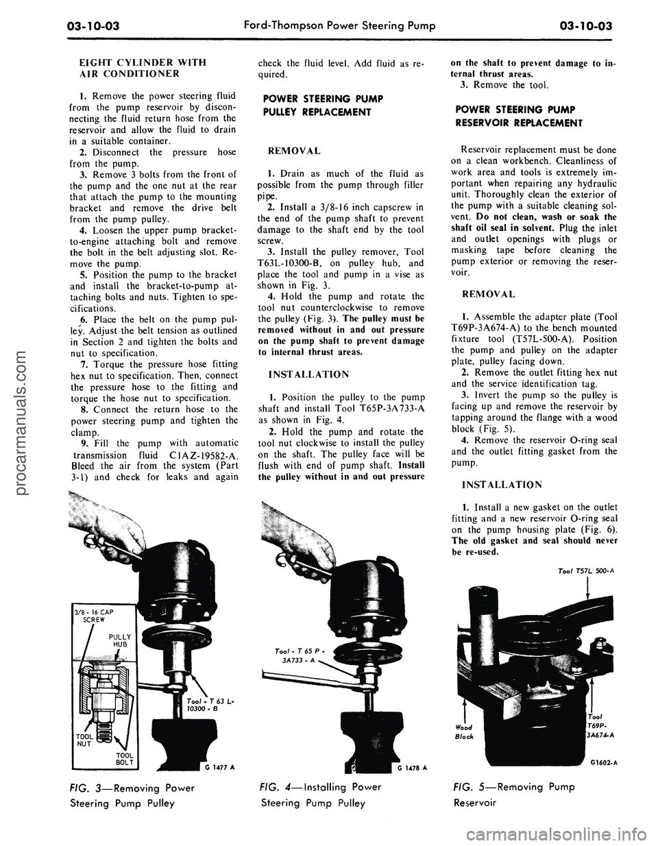
3.
Install the pulley remover, Tool
T63L-1O3OO-B, on pulley hub, and
place the tool and pump in a vise as
shown in Fig. 3.
4.
Hold the pump and rotate the
tool nut counterclockwise to remove
the pulley (Fig. 3). The pulley must be
removed without in and out pressure
on the pump shaft to prevent damage
to internal thrust areas.
INSTALLATION
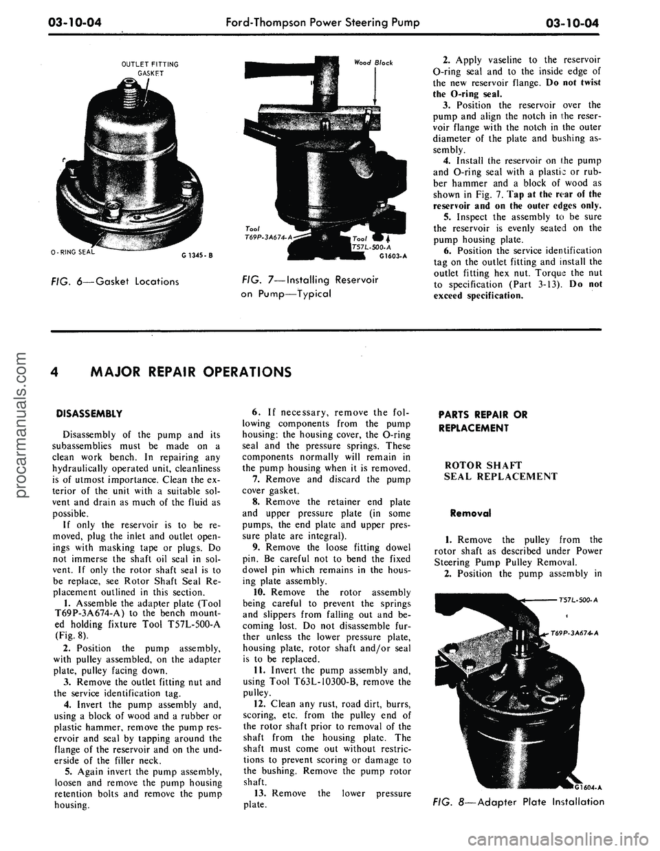
1.
Position the pulley to the pump
shaft and install Tool T65P-3A733-A
as shown in Fig. 4.
2.
Hold the pump and rotate the
tool nut clockwise to install the pulley
on the shaft. The pulley face will be
flush with end of pump shaft. Install
the pulley without in and out pressure
on the shaft to prevent damage to in-
ternal thrust areas.
3.
Remove the tool.
POWER STEERING PUMP
RESERVOIR REPLACEMENT
Reservoir replacement must be done
on a clean workbench. Cleanliness of
work area and tools is extremely im-
portant when repairing any hydraulic
unit. Thoroughly clean the exterior of
the pump with a suitable cleaning sol-
vent. Do not clean, wash or soak the
shaft oil seal in solvent. Plug the inlet
and outlet openings with plugs or
masking tape before cleaning the
pump exterior or removing the reser-
voir.
REMOVAL
1.
Assemble the adapter plate (Tool
T69P-3A674-A) to the bench mounted
fixture tool (T57L-5OO-A). Position
the pump and pulley on the adapter
plate, pulley facing down.
2.
Remove the outlet fitting hex nut
and the service identification tag.
3.
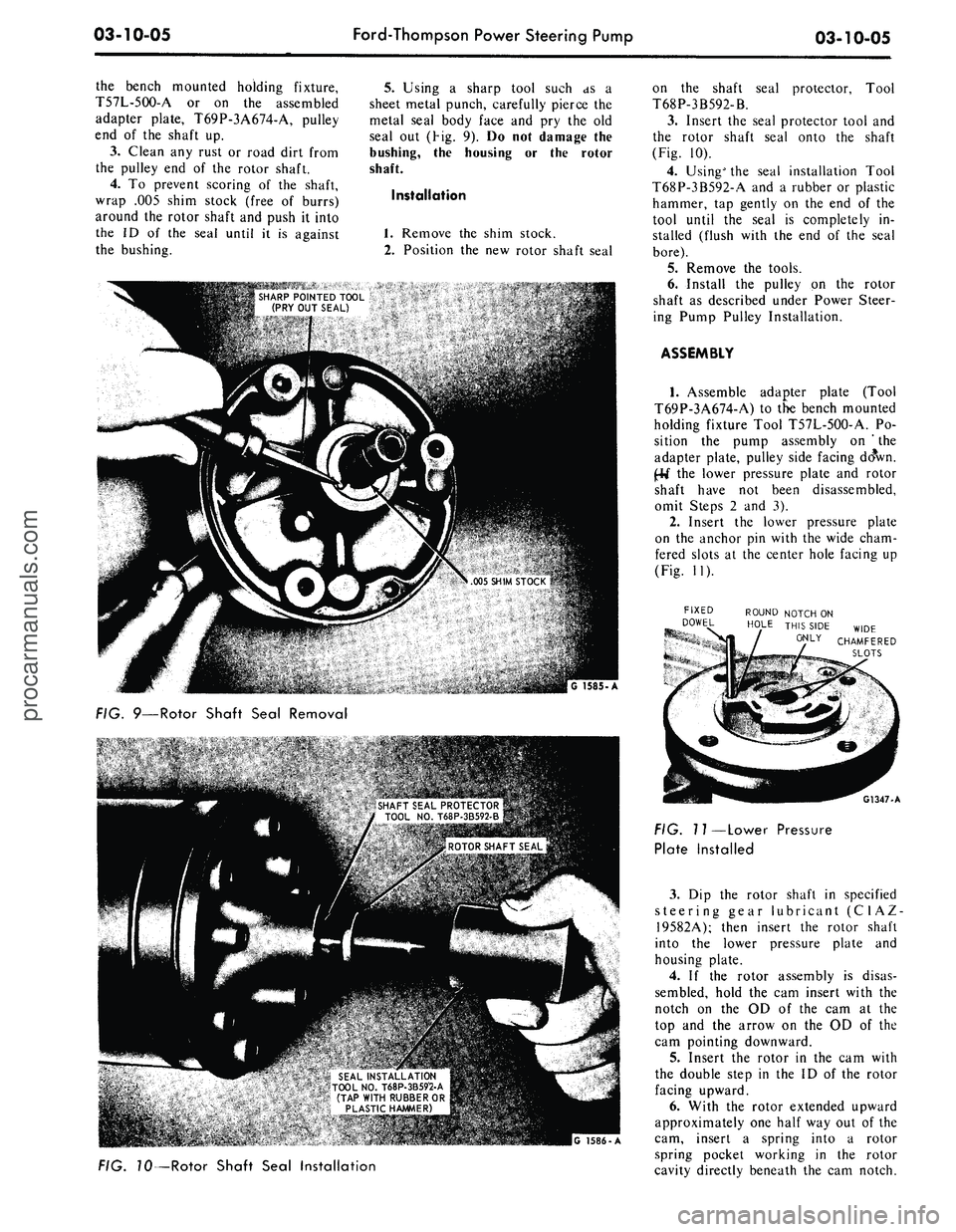
Invert the pump so the pulley is
facing up and remove the reservoir by
tapping around the flange with a wood
block (Fig. 5).
4.
Remove the reservoir O-ring seal
and the outlet fitting gasket from the
pump.
INSTALLATION
Tool • T 63 L-
10300 -
G 1477 A
FIG. 3—Removing Power
Steering Pump Pulley
1478 A
FIG. 4—Installing Power
Steering Pump Pulley
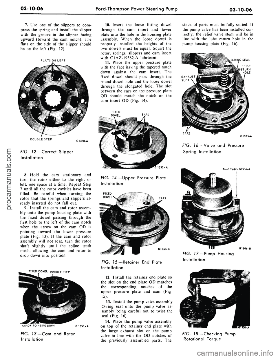
1.
Install a new gasket on the outlet
fitting and a new reservoir O-ring seal
on the pump housing plate (Fig. 6).
The old gasket and seal should never
be re-used.
Too/
T57L 500-A
G1602-A
FIG. 5—Removing Pump
Reservoirprocarmanuals.com
Page 165 of 413

03-10-04
Ford-Thompson Power Steering Pump
03-10-04
OUTLET FITTING
GASKET
Wood Block
0-RING SEAL
G1345-
-500-
A
G1603- A
FIG. 6—Gasket Locations
FIG.
7—Installing
Reservoir
on Pump—Typical
2.
Apply vaseline to the reservoir
O-ring seal and to the inside edge of
the new reservoir flange. Do not twist
the O-ring seal.
3.
Position the reservoir over the
pump and align the notch in the reser-
voir flange with the notch in the outer
diameter of the plate and bushing as-
sembly.
4.
Install the reservoir on the pump
and O-ring seal with a plastic or rub-
ber hammer and a block of wood as
shown in Fig. 7. Tap at the rear of the
reservoir and on the outer edges only.
5.
Inspect the assembly to be sure
the reservoir is evenly seated on the
pump housing plate.
6. Position the service identification
tag on the outlet fitting and install the
outlet fitting hex nut. Torque the nut
to specification (Part 3-13). Do not
exceed specification.
MAJOR REPAIR OPERATIONS
DISASSEMBLY
Disassembly of the pump and its
subassemblies must be made on a
clean work bench. In repairing any
hydraulically operated unit, cleanliness
is of utmost importance. Clean the ex-
terior of the unit with a suitable sol-
vent and drain as much of the fluid as
possible.
If only the reservoir is to be re-
moved, plug the inlet and outlet open-
ings with masking tape or plugs. Do
not immerse the shaft oil seal in sol-
vent. If only the rotor shaft seal is to
be replace, see Rotor Shaft Seal Re-
placement outlined in this section.
1.
Assemble the adapter plate (Tool
T69P-3A674-A) to the bench mount-
ed holding fixture Tool T57L-5OO-A
(Fig. 8).
2.
Position the pump assembly,
with pulley assembled, on the adapter
plate, pulley facing down.
3.
Remove the outlet fitting nut and
the service identification tag.
4.
Invert the pump assembly and,
using a block of wood and a rubber or
plastic hammer, remove the pump res-
ervoir and seal by tapping around the
flange of the reservoir and on the und-
erside of the filler neck.
5.
Again invert the pump assembly,
loosen and remove the pump housing
retention bolts and remove the pump
housing.
6. If necessary, remove the fol-
lowing components from the pump
housing: the housing cover, the O-ring
seal and the pressure springs. These
components normally will remain in
the pump housing when it is removed.
7.
Remove and discard the pump
cover gasket.
8. Remove the retainer end plate
and upper pressure plate (in some
pumps, the end plate and upper pres-
sure plate are integral).
9. Remove the loose fitting dowel
pin. Be careful not to bend the fixed
dowel pin which remains in the hous-
ing plate assembly.
10.
Remove the rotor assembly
being careful to prevent the springs
and slippers from falling out and be-
coming lost. Do not disassemble fur-
ther unless the lower pressure plate,
housing plate, rotor shaft and/or seal
is to be replaced.
11.
Invert the pump assembly and,
using Tool T63L-1O3OO-B, remove the
pulley.
12.
Clean any rust, road dirt, burrs,
scoring, etc. from the pulley end of
the rotor shaft prior to removal of the
shaft from the housing plate. The
shaft must come out without restric-
tions to prevent scoring or damage to
the bushing. Remove the pump rotor
shaft.
13.
Remove the lower pressure
plate.
PARTS REPAIR OR
REPLACEMENT
ROTOR SHAFT
SEAL REPLACEMENT
Removal
1.
Remove the pulley from the
rotor shaft as described under Power
Steering Pump Pulley Removal.
2.
Position the pump assembly in
T57L-500-A
T69P-3A674-A
•
G1604-A
FIG. 8—Adapter Plate Installationprocarmanuals.com
Page 166 of 413

03-10-05
Ford-Thompson Power Steering Pump
03-10-05
the bench mounted holding fixture,
T57L-5OO-A or on the assembled
adapter plate, T69P-3A674-A, pulley
end of the shaft up.
3.
Clean any rust or road dirt from
the pulley end of the rotor shaft.
4.
To prevent scoring of the shaft,
wrap .005 shim stock (free of burrs)
around the rotor shaft and push it into
the ID of the seal until it is against
the bushing.
5.
Using a sharp tool such as a
sheet metal punch, carefully pierce the
metal seal body face and pry the old
seal out (Hg. 9). Do not damage the
bushing, the housing or the rotor
shaft.
Installation
1.
Remove the shim stock.
2.
Position the new rotor shaft seal
.* SHARP POINTED TOOL
(PRY OUT SEAL)
FIG. 9—Rotor Shaft Seal Removal
s- •:?
. SHAFT SEAL PROTECTOR
TOOL NO. T68P-3B592-B
on the shaft seal protector, Tool
T68P-3B592-B.
3.
Insert the seal protector tool and
the rotor shaft seal onto the shaft
(Fig. 10).
4.
Using" the seal installation Tool
T68P-3B592-A and a rubber or plastic
hammer, tap gently on the end of the
tool until the seal is completely in-
stalled (flush with the end of the seal
bore).
5.
Remove the tools.
6. Install the pulley on the rotor
shaft as described under Power Steer-
ing Pump Pulley Installation.
ASSEMBLY
1.
Assemble adapter plate (Tool
T69P-3A674-A) to the bench mounted
holding fixture Tool T57L-5OO-A. Po-
sition the pump assembly on ' the
adapter plate, pulley side facing doVn.
JrM" the lower pressure plate and rotor
shaft have not been disassembled,
omit Steps 2 and 3).
2.
Insert the lower pressure plate
on the anchor pin with the wide cham-
fered slots at the center hole facing up
(Fig. 11).
FIXED ROUND NOTCH ON
DOWEL HOLE THIS SIDE WIDE
0NLY CHAMFERED
SLOTS
G1347-A
FIG. 10—Rotor Shaft Seal Installation
FIG. 11—Lower Pressure
Plate Installed
3.
Dip the rotor shaft in specified
steering gear lubricant (C1AZ
19582A); then insert the rotor shaft
into the lower pressure plate and
housing plate.
4.
If the rotor assembly is disas-
sembled, hold the cam insert with the
notch on the OD of the cam at the
top and the arrow on the OD of the
cam pointing downward.
5.
Insert the rotor in the cam with
the double step in the ID of the rotor
facing upward.
6. With the rotor extended upward
approximately one half way out of the
cam, insert a spring into a rotor
spring pocket working in the rotor
cavity directly beneath the cam notch.procarmanuals.com
Page 167 of 413

03-10-06
Ford-Thompson Power Steering Pump
03-10-06
7.
Use one of the slippers to com-
press the spring and install the slipper
with the groove in the slipper facing
upward (toward the cam notch). The
flats on the side of the slipper should
be on the left (Fig. 12).
FLATS ON LEFT
DOUBLE STEP
G1350-A
FIG. 72—Correct Slipper
Installation
8. Hold the cam stationary and
turn the rotor either to the right or
left, one space at a time. Repeat Step
7 until all the rotor cavities have been
filled. Be careful when turning the
rotor that the springs and slippers al-
ready inserted do not fall out.
9. Install the cam and rotor assem-
bly onto the pump housing plate with
the fixed dowel passing through the
first hole to the left of the cam notch
when the arrow on the cam OD is
pointing toward the lower pressure
plate (Fig. 13). If the cam and rotor
assembly will not seat, turn the rotor
shaft slightly until the spline teeth
mesh, allowing the cam and rotor to
drop down into position.
FIXED DOWEL D0|JBLE STEP
ARROW POINTING DOWN
G 1351-A
FIG. 13—Cam and Rotor
Installation
10.
Insert the loose fitting dowel
through the cam insert and lower
plate into the hole in the housing plate
assembly. When the loose dowel is
properly installed the heights of the
two dowels must be equal. Squirt the
rotor, springs, slippers and cam insert
with C1AZ-19582-A lubricant.
11.
Place the upper pressure plate
with the face having the tapered notch
down against the cam insert. The
fixed dowel should pass through the
round dowel hole and the loose dowel
through the elongated hole. The slot
between the ears on the pressure plate
OD should match the notch on the
cam insert OD (Fig. 14).
EARS
'G 1352-A
FIG. 74—Upper Pressure Plate
Installation
\ EARS
G1353-B
FIG. 75—Retainer End Plate
Installation
12.
Install the retainer end plate so
the slot on the end plate OD matches
the corresponding notches of the
upper pressure plate and cam (Fig
15).
13.
Install the pump valve assembly
O-ring seal onto the pump valve as-
sembly being careful not to twist the
seal (Fig. 16).
14.
Place the pump valve assembly
on top of the retainer end plate with
the large exhaust slot on the pump
valve in line with the OD notches of
the previously assembled parts. The
stack of parts must be fully seated. If
the pump valve has been installed cor-
rectly, the relief valve stem will be in
line with the lube return hole in the
pump housing plate (Fig. 16).
O-RING SEAL
EARS
G1605-A
FIG. 16 —Valve and Pressure
Spring Installation
Tool 169P-3B586-A
G1606-B
FIG. 17—Pump Housing
Installation
FIG. 18 -Checking Pump
Rotational Torqueprocarmanuals.com
Page 168 of 413

03-10-07
Ford-Thompson Power Steering Pump
03-10-07
15.
Place small amounts of vaseline
on the pump housing plate to hold the
cover gasket in place. Install the gas-
ket on the pump housing plate.
16.
Insert the pressure plate springs
into the pockets in the pump valve as-
sembly. Vaseline may be placed in the
spring pockets to hold the springs in
position (Fig. 17).
17.
Using Tool T69P-3B586-A,
plug the intake hole in the housing
(Fig. 17).
18.
Lubricate the inside of the
housing and the housing cover seal
with C1AZ-19582-A lubricant. Fabri-
cate two studs (3/8-16x1.55 ) to be
used as positioning guides. Install one
in the housing plate bolt hole closest
to the drain hole and one in the bolt
hole diametrically opposite.
19.
Align the small diameter lube
hole in the housing rim with the lube
hole in the housing plate.
20.
Install the housing, applying an
even, downward pressure. The pres-
sure plate springs must not be jarred
and moved out of position. Remove
the guide studs.
21.
Install the housing retaining
bolts finger tight.
22.
Remove Tool T69P-3B586-A.
23.
Torque the retaining bolts even-
ly to 28-32 ft-lbs until the housing
flange contacts the gasket.
24.
Install a 3/8x16 hex head
screw, finger tight, into the end of the
rotor shaft. Using a torque wrench,
check the input torque of the shaft
(Fig. 18). The torque should not ex-
ceed 15 in-lbs. If it does, loosen the
retaining bolts slightly, rotate the
rotor shaft, retorque the bolts evenly
and again check the shaft torque. The
pump must not be used if the shaft
torque exceeds 15 in-lbs.
25.
Release the pin in the bench
holding fixture and agitate the pump
assembly back and forth. If there is a
rattle, the pressure plate springs have
fallen out of their seats and must be
reinstalled.
26.
Install the reservoir O-ring on
the housing plate being careful not to
twist the O-ring. Apply vaseline to the
seal and to the ID of the reservoir
flange.
27.
Install the reservoir, aligning
the notch in the reservoir flange with
the notch in the OD of the pump
housing plate and bushing assembly.
Using only a plastic or rubber ham-
mer, tap at the rear on the outer cor-
ners of the reservoir to avoid damage.
28.
Inspect the assembly to deter-
mine if the reservoir is seated on the
housing plate.
29.
Install the service identification
tag on the outlet valve fitting.
30.
Install the outlet valve fitting
nut and torque to 43-47 ft-lbs.
31.
Invert the pump assembly.
32.
If the pulley was removed, in-
stall the correct pulley using Tool
T65P-3A733-A.procarmanuals.com