Page 313 of 413
07-02-05
C4 Automatic Transmission
07 02-05
7E263
NUT
382384-S4
XP3 TRANSMISSION
D 1813-A
FIG.
6—Manual
Linkage—Console Shift—Ford and Meteor
TRANSMISSION
MANUAL
LEVER
MANUAL S™D
LINKAGE ROD
7340
FLAT WASHER
372285-S8
D1825-A
FIG. 7—Manual Linkage—Console Shift—Fairlane and Montegoprocarmanuals.com
Page 314 of 413

07-02-06
C4 Automatic Transmission
07-02-06
PLUG-7256
•HANDLE-7217
BUTTON-7C439
DIAL HOUSING
ASSEMBLY-7E034
POINTER BACK-UP
SHIELD
ENGAGE FLATS OF STUD IN SLOT OF
ROD BEFORE APPLYING TORQUE
D2022-A
FIG. 8—Manual Linkage—Console Shift—Mustang
ACTUATOR LEVER ATTACHING BOLT
D1812-A
FIG. 9—Neutral Start Switch Adjustments—Console Shift—Ford-Meteor
9. Turn the ignition key to the
ACC position and place the selector
lever in the reverse position and check
the operation of the back-up lights.
Turn the key off.
10.
Place the console top panel on
the console and install the retaining
screws.
11.
Position the selector lever de-
tent control and handle on the selector
lever and secure with the four plates
and attaching screws.
FAIRLANE-MONTEGO
1.
With the manual linkage proper-
ly adjusted, check the starter en-
gagement circuit in all positions. The
circuit must be open in all drive posi-
tions and closed only in park and neu-
tral.
Gauge Pin
(No.43 Drill)
NEUTRAL START
SWITCH
Dl759-A
70—Neutral Start Switch
Adjustments—Console Shift—
Fairlane-Montegoprocarmanuals.com
Page 315 of 413

07-02-07
C4 Automatic Transmission
07-02-07
2.
Remove the selector lever handle
from the lever.
3.
Remove the trim panel from the
top of the console.
4.
Remove the cover and dial indi-
cator as an assembly.
5.
Remove the four screws that se-
cure the selector lever retainer to the
selector lever housing. Lift the retainer
from the housing.
6. Loosen the two combination
starter neutral and back-up light
switch attaching screws (Fig. 10).
7.
Move the selector lever back and
forth until the gauge pin (No. 43 drill)
can be fully inserted into the gauge
pin holes (Fig. 10).
8. Place the transmission selector
lever firmly against the stop of the
neutral detent position.
9. Slide the combination starter
neutral and back-up light switch for-
ward or rearward as required, until
the switch actuating lever contacts the
selector lever.
10.
Tighten the switch attaching
screws and remove the gauge pin.
Check for starting in the park posi-
tion.
11.
Turn the ignition key to the
ACC position and place the selector
lever in the reverse position and check
the operation of the back-up lights.
Turn the key off.
12.
Position the selector lever re-
tainer to the selector lever housing.
Install the four attaching screws.
13.
Install the cover and dial indi-
cator.
14.
Install the trim panel on the top
of the console. Install the selector
lever handle.
MUSTANG
1.
With the manual lever properly
NEUTRAL
START
SWITCH
(D1439-A
FIG. 11—Neutral Start Switch
Adjustments—Console Shift—
Mustang
adjusted, loosen the two switch attach-
ing bolts (Fig. 11).
2.
With the transmission manual
lever in neutral, rotate the switch and
insert the gauge pin (No. 43 drill
shank end) into the gauge pin holes of
the switch. The gauge pin has to be
inserted to a full 31/64 inch into the
three holes of the switch (Fig. 11).
3.
Torque the two switch attaching
bolts to specification. Remove the
gauge pin from the switch.
4.
Check the operation of the
switch. The engine should start only
with the transmission selector lever in
Neutral and Park.
NEUTRAL START SWITCH
REPLACEMENT—CONSOLE SHIFT
On vehicles equipped with a column
mounted neutral start switch, refer to
Part 7-1, Section 2, for the replace-
ment procedures.
FORD-METEOR
1.
Remove the four screws and
plates securing the selector lever
handle to the lever. Remove the
handle and detent control.
2.
Remove the two screws from the
rear of the console top panel. Pull the
panel back to unhook it from the
front of the console and remove the
panel.
3.
Remove the two screws securing
the dial indicator assembly to the se-
lector lever housing and remove the
indicator assembly.
4.
Disconnect the neutral start
switch wires at the plug connector.
Remove the wires from under the re-
taining clip.
5.
Remove the two screws securing
the neutral start switch to the selector
lever housing and remove the switch
(Fig. 9).
6. Position the neutral start switch
to the selector lever housing and in-
stall the two attaching screws.
7.
Adjust the neutral start switch as
outlined under the Neutral Start
Switch Adjustment procedures in this
section.
8. Connect the neutral start switch
wires to the plug connector. Position
the wires in the retaining clip and
close the clip.
9. Place the console top panel on
the console and install the retaining
screws.
10.
Position the selector lever de-
tent control and handle on the selector
lever and secure with the four plates
and attaching screws.
FAIRLANE-MONTEGO
1.
Remove the selector lever handle
from the lever.
2.
Remove the trim panel from the
top of the console.
3.
Remove the cover and dial indi-
cator as an assembly.
4.
Remove the four screws that se-
cure the selector lever retainer to the
selector lever housing. Lift the retainer
from the housing.
5.
Remove the two screws securing
the neutral start switch to the selector
lever housing. Disconnect the neutral
start switch wires at the plug connec-
tor and remove the switch.
6. Position the neutral start switch
to the selector lever housing and in-
stall the two attaching screws.
7.
With the selector lever in neu-
tral,
move the selector lever back and
forth until the gauge pin (No. 43 drill)
can be fully inserted into the gauge
pin holes (Fig. 10).
8. Place the transmission selector
lever firmly against the stop of the
neutral detent position.
9. Slide the combination starter
neutral and back-up light switch for-
ward or rearward as required, until
the switch actuating lever contacts the
selector lever.
10.
Tighten the switch attaching
screws and remove the gauge pin.
11.
Connect the neutral start switch
wires to the plug connector and check
for starting in the park position.
12.
Position the selector lever re-
tainer to the selector lever housing.
Install the attaching screws.
13.
Install the cover and dial indi-
cator.
14.
Install the trim panel on the top
of the console. Install the selector
lever handle
MUSTANG
1.
Remove the downshift linkage
rod from the transmission downshift
lever.
2.
Apply penetrating oil to the
downshift lever shaft and nut. Remove
the transmission downshift outer lever
retaining nut and lever (Fig. 11).
3.
Remove the two neutral start
switch attaching bolts.
4.
Disconnect the multiple wire
connector. Remove the neutral switch
from the transmission.
5.
Install the neutral start switch on
the transmission. Install the two at-
taching bolts.
6. With the transmission manual
lever in neutral, rotate the switch and
install gauge pin (No. 43 drill) into
the gauge pin hole (Fig. 11).
7.
Tighten the switch attaching
bolts to specification and remove the
gauge pin.procarmanuals.com
Page 316 of 413

07-02-08
C4 Automatic Transmission
07-02-08
8. Install the outer downshift lever
and attaching nut, and torque the nut
to specification. Install the downshift
linkage rod to the downshift lever.
9. Install the switch wires. Connect
the wire multiple connector. Check
the operation of the switch in each de-
tent position. The engine should start
only with the transmission selector
lever in N (neutral) and P (park).
SELECTOR LEVER
REPLACEMENT—CONSOLE SHIFT
FORD-METEOR
1.
Raise the vehicle and disconnect
the link assembly from the selector
lever arm (Fig. 6).
2.
Lower the vehicle. Remove the
four screws and plates securing the se-
lector lever handle to the lever. Re-
move the handle and detent control.
3.
Remove the two screws from the
rear of the console top panel. Pull the
panel back to unhook it from the
front of the console and remove the
panel.
4.
Disconnect the neutral start
switch wires at the plug connector.
Disconnect the bulb socket from the
quadrant.
5.
Remove the four bolts that at-
tach the selector lever housing to the
floor pan and remove the selector
lever and housing.
6. Position the new selector lever
and housing assembly on the floor pan
and install the attaching bolts.
7.
Connect the bulb socket to the
quadrant and the neutral start switch
wires to the plug connector.
8. Raise the vehicle and secure the
link assembly to the selector lever arm
with the bushing, insulator, flat wash-
er and cotter pin (Fig. 6). Lower the
vehicle.
9. Place the console top panel on
the console and install the retaining
screws.
10.
Position the selector lever de-
tr*rtt control and handle on the selector
lever and secure with the four plates
and attaching screws.
FAIRLANE-MONTEGO
1.
Raise the vehicle on a hoist or
jack stands.
2.
Remove the retainer that secures
the manual linkage rod to the lower
end of the manual lever (Fig. 7).
3.
Remove the flat washer and two
insulator washers and disconnect the
rod from the arm.
4.
Working from inside of the vehi-
cle,
remove the selector lever handle
attaching screw. Lift the handle off
the selector lever.
DETENT PAWL
LOCK NUT
DETENT PAWL
ADJUSTMENT SCREW
DETENT PLATE
D 1644-A
FIG. 72—Typical Selector Lever Detent Pawl Adjustment
5.
Remove the console trim panel
from the top of the console. Remove
the console retaining screws and re-
move the console.
6. Remove the cover and dial indi-
cator as an assembly.
7.
Remove the four screws that se-
cure the selector lever retainer to the
selector lever housing. Lift the retainer
from the housing.
8. Disconnect the neutral start
switch wires at the plug connector.
Disconnect the bulb socket from the
selector lever housing.
9. Remove the three bolts that se-
cure the selector lever control housing
to the console. Lift the selector lever
housing from the console.
10.
Remove the selector lever to
housing attaching nut. Remove the
lever from the housing.
11.
Install the selector lever in the
housing and install the attaching nut.
Torque the nut to 20 to 25 ft-31bs.
12.
Install the selector lever handle.
13.
Position the selector lever as
shown in Figure 12. With a feeler
gauge, check the clearance between
the detent pawl and plate. The clear-
ance should be 0.005 to 0.010 inch. If
necessary adjust the height of the de-
tent pawl as shown in Figure 12.
14.
Remove the handle from the se-
lector lever.
15.
Position the selector lever hous-
ing in the console and install the three
attaching bolts. Do not tighten the at-
taching bolts at this time.
16.
Connect the bulb socket to the
selector lever housing and the neutral
start switch wires to the plug connec-
tor.
17.
Position the selector lever re-
tainer to the selector lever housing.
Install the four attaching screws.
18.
Install the cover and dial indi-
cator.
19.
Place the console in position
and install the retaining bolts. Tighten
the selector lever housing attaching
bolts.
20.
Position the console trim panel
and secure it with the attaching
screws.
21.
Install the handle and the but-
ton on the selector lever. Secure the
handle with the set screw.
22.
Secure the manual linkage rod
to the arm with two insulating wash-
ers,
a flat washer and a retainer (Fig.
7).
23.
Adjust the linkage as required.
J r the vehicle.
MUSTANG
1.
Raise the vehicle and remove the
manual lever control rod attaching nut
(Fig. 8).
2.
Lower the vehicle, remove the se-
lector lever handle attaching screw.
3.
Remove the dial housing attach-
ing screws and the housing.
4.
Remove the two pointer back-up
shield attaching screws and remove
the shield.
5.
Disconnect the dial indicator
light.
6. Remove the selector housing and
lever assembly attaching bolts. Re-
move the selector lever and housing.
7.
Remove the selector lever to
housing attaching nut. Remove the
lever from the housing.
8. Install the selector lever in the
housing and install the attaching nut.
Torque the nut to 20 to 25 ft-lbs.
9. Install the selector lever handle.
10.
Position the selector lever as
shown in Figure 12. With a feeler
gauge check the clearance between the
detent pawl and plate. The clearance
should be 0.005 to 0.010 inch. If nec-
essary adjust the height of the detent
pawl as shown in Figure 12.procarmanuals.com
Page 317 of 413

07-02-09
C4 Automatic Transmission
07-02-09
11.
Remove the handle from the se-
lector lever.
12.
Install the selector housing and
lever assembly as shown in Figure 8.
Torque the attaching bolts 4-6 ft-lbs.
13.
Connect the dial indicator light.
14.
Install the pointer back-up
shield on the housing and lever assem-
bly.
15.
Install the dial housing and
tighten the attaching screws.
16.
Install the selector lever handle
and tighten the attaching screw.
17.
Position the selector lever in the
D position.
18.
Raise the vehicle. Install the
transmission manual lever rod to the
selector lever. Adjust the manual link-
age.
19.
Lower the vehicle and check the
transmission operation in each selo:c-
tor lever detent position.
BAND ADJUSTMENT
INTERMEDIATE BAND
1.
Clean all the dirt from the band
adjusting screw area. Remove and dis-
card the locknut.
2.
Install a new locknut on the ad-
justing screw. With the tool shown in
Fig. 13, tighten the adjusting screw
until the tool handle clicks. The tool is
a pre-set torque wrench which clicks
and overruns when the torque on the
adjusting screw reaches 10 ft-lbs.
I D1854-A
FIG. 13—Adjusting Intermediate
Band
Tool-T59P-77370-B
D1855-A
FIG. 14—Adjusting Low-Reverse
Band
3.
Back off the adjusting screw ex-
actly 1 3/4 turns.
4.
Hold the adjusting screw from
turning and torque the lock nut to
specification.
LOW-REVERSE BAND
1.
Clean all the dirt from the band
adjusting screw area. Remove and dis-
card the locknut.
2.
Install a new locknut on the ad-
justing screw with the tools shown in
Fig. 14, tighten the adjusting screw
until the tool handle clicks. The tool is
a pre-set torque wrench which clicks
and overruns when the torque on the
adjusting screw reaches 10 ft-lbs.
3.
Back off the adjusting screw ex-
actly 3 full turns.
4.
Hold the adjusting screw from
turning and torque the lock nut to
specification.
OIL PAN AND CONTROL
VALVE BODY REPLACEMENT
1.
Raise the vehicle so the trans-
mission oil pan is accessible.
2.
Drain the transmission fluid.
If the same fluid is to be used
again, filter the fluid through a 100
mesh screen. Re-use the fluid only if it
is in good condition.
3.
Remove the transmission fluid
pan attaching bolts, pan and gasket.
4.
Remove the valve body-to-case
attaching bolts (Fig. 25). Remove the
valve body from the case and the
transmission inner control levers.
5.
Refer to the Major Repair Oper-
ation for control valve body repair op-
eration.
6. Thoroughly clean and remove all
the gasket material from the pan and
the pan mounting face of the case. In-
stall the valve body to the case, engag-
ing the transmission inner control le-
vers with the valve body manual and
downshift valves.
7.
Install the eight valve body to
case attaching bolts. Torque the bolts
to specification. Operate the external
manual and downshift levers to check
for proper travel of the valve body
manual and downshift valves.
8. Place a new gasket on the pan.
Install the pan and attaching bolts.
Torque the bolts to specification. In-
stall the fluid filler tube if it was re-
moved. Torque the attaching nut to
specifications.
9. Lower the vehicle and fill the
transmission with fluid. Check the
transmission pan area for fluid leak-
age.
INTERMEDIATE SERVO
REPLACEMENT
1.
Raise the vehicle and remove the
four servo cover-to-case attaching
bolts.
2.
Remove the servo cover, gasket,
piston, and piston return spring. Re-
move the piston from the cover (Fig.
45).
3.
Remove the piston seals and
cover gasket.
4.
Install new piston seals on the
piston. Lubricate the piston seals with
clean transmission fluid. Install the
servo piston in the cover.
5.
Install the piston retvrn spring in
the case. Place a new gasicet on the
cover. Install the piston and cover into
the transmissic se. Use two 5/16
18 x 1 1/4 bolts, 180 degrees apart to
position the cover against the case.
6. Install the two servo cover at-
taching bolts. Remove the two 1 1/4
inch bolts and install two attaching
bolts.
Torque the bolts to specifica-
tion.
7.
Adjust the intermediate band.
Lower the vehicle and check the trans-
mission fluid level.
8. If the band can not be adjusted
properly, the struts are not in posi-
tion. Remove the pan and valve body.
Install the struts, valve body, pan, and
adjust the band. Refill the transmis-
sion with fluid.
LOW-REVERSE SERVO
PISTON REPLACEMENT
1.
Raise the vehicle on a hoist.
2.
Loosen the reverse band adjust-
ing screw lock nut. Tighten the reverse
band adjusting screw to 10 ft-lbs tor-
que.
(Tightening the screw will insure
that the band strut will be held against
the case by the band, preventing it
from falling down when the reverse
servo piston assembly is removed).
3.
Remove the four servo cover to
case attaching bolts. Remove the iden-
tification tag and vent tube retaining
clip.
Remove the servo cover and s»»^
from the case.
4.
Remove the servo piston from
the case. The piston seal cannot be re-
placed, without replacing the piston.
The seal is bonded to the piston.
5. To remove the piston from the
stem, insert a small screw driver in the
hole of the piston (Fig. 44). Remove
the piston attaching nut.
6. Position the accumulator spring
and spacer (Fig. 43) on the piston
stem. Make sure the crowned side of
the spring is facing toward the rod.
Install.a new piston on the piston re-
taining shaft. Install the attaching nut.
Torque the nut to specification.procarmanuals.com
Page 318 of 413

07-02-10
C4 Automatic Transmission
07-02-10
7.
Install
the
piston into
the
case.
Install
a new
seal
on the
cover. Install
the cover
by
using
two
5/16—18 bolts,
1
1/4
inch long,
at
180
degrees apart
to position
the
servo cover
on the
case.
Install
the
vent tube retaining
clip
and
identification
tag.
Install
two
cover attaching bolts. Remove
the two
installing bolts
and
install
the
last
two
attaching bolts. Torque
the
cover-
to-case attaching bolts
to
specifica-
tion.
8. Adjust
the
low-reverse band.
Lower
the
vehicle
and
check
the
trans-
mission fluid level.
9.
If the
band
can not be
adjusted
properly,
the
struts
are not in
posi-
tion. Remove
the
fluid
pan and
valve
body. Install
the
struts, valve body,
pan
and
adjust
the
band. Refill
the
transmission with fluid.
EXTENSION HOUSING
BUSHING
AND
REAR
SEAL REPLACEMENT
1.
Disconnect
the
drive shaft from
the transmission.
2.
When only
the
rear seal needs
replacing, carefully remove
it
with
a
tapered chisel
or the
tools shown
in
Fig.
15.
Remove
the
bushing
as
shown
in
Fig. 16. Use the
bushing remover
carefully
so
that
the
spline- seal
is not
damaged.
3.
When installing
a new
bushing
use
the
special tool shown
in
Fig.
17.
4.
Before installing
a new
seal,
in-
spect
the
sealing surface
of the
univer-
sal joint yoke
for
scores.
If
scores
are
found, replace
the
yoke.
5.
Inspect
the
counterbore
of the
housing
for
burrs
and
remove with
crocus cloth.
6. Install
the
seal into
the
housing
with
the
tool shown
in Fig. 18. The
seal should
be
firmly seated
in the
bore.
Coat
the
inside diameter
of the
fiber portion
of the
seal with
B8A-
19589-A lubricant.
7.
Coat
the
front universal joint
spline with B8A-19589-A lubricant
and install
the
drive shaft.
EXTENSION HOUSING
AND
GOVERNOR REPLACEMENT
1.
Raise
the
vehicle
on the
hoist.
2.
Remove
the
drive shaft. Position
the transmission jack
to
support
the
transmission.
3.
Remove
the
speedometer cable
from
the
extension housing.
4.
Remove
the
extension housing
to
crossmember mount attaching bolts.
Raise
the
transmission
and
remove
the
mounting
pad
between
the
extension
housing
and the
crossmember.
Tool—
I775-AB
Tool—
T50T-100-A
FIG. 15—Removing Extension Housing
EXTENSION HOUSING
rIG. 16—Removing Extension
Housing Bushing
BUSHING
I Tool—T57P-76 7-B
^mmmfm^
0^7000-Ht
EXTENSION HOUSING
D1O26-B
FIG. 17—Installing Extension
Housing Bushing
D 1927-A
5.
Loosen
the
extension housing
at-
taching bolts
to
drain
the
transmission
fluid. Disconnect
the
exhaust inlet
pipes
at the
manifold
and
lower
the
inlet pipes.
6. Remove
the six
extension
housing-to-case attaching bolts
and re-
move
the
extension housing.
7.
Remove
the
governor housing
to
governor distributor attaching bolts
(Fig.
19).
Remove
the
governor hous-
ing from
the
distributor.
8. Refer
to
Major Repair Opera-
tions
for
governor repair operations.
9. Install
the
governor housing
on
the governor distributor
(Fig.
19). In-
stall
the
attaching bolts
and
torque
the
bolts
to
specification.
Tool—
T6
U-7657-A
or B,
7657AA,
or
7657-AB
EXTENSION HOUSING
REAR SEAL
FIG. 18—Installing Extension Housing Seal
D 2042-A
GOVERNOR GOVERNOR GOVERNOR
BOLTS
(4)
DISTRIBUTOR DISTRIBUTOR
SLEEVE
I
D1859-A
FIG. 79—Governor Installed
10.
Install
a new
extension housing
gasket
on the
case. Install
the
exten-
sion housing
and six
attaching bolts.
Torque
the
bolts
to
specification.
11.
Install
the
transmission mount-
ing
pad on the
crossmember. Lower
the transmission
and
install
the
exten-
sion housing
to
crossmember attach-
ing bolts. Torque
the
bolts
to
specifi-
cation. Remove
the
transmission jack.
12.
Install
the
speedometer cable
in
the extension housing. Install
the
drive
shaft.
13.
Install
the
inlet pipes
on the
manifold.
14.
Lower
the
vehicle
and
fill
the
transmission with fluid.
15.
Check
the
extension housing
area
for
fluid leakage.procarmanuals.com
Page 319 of 413

07-02-11
C4 Automatic Transmission
07-02-11
REMOVAL AND INSTALLATION
An oil impregnated plastic grommet
is incorporated in the end of the man-
ual shift linkage lever arm on all col-
umn shift vehicles. A special tool
T67P-7341-A is required to install the
grommet in the manual lever, and to
install the manual linkage rod into the
grommet. Refer to Part 7-1, Section
2,
for the grommet replacement pro-
cedures.
TRANSMISSION REMOVAL
1.
Raise the vehicle and remove the
converter cover attaching bolts, at the
lower front side of the converter hous-
ing. Remove the cover.
2.
Remove the two conveter drain
plugs (Fig. 20). Drain the fluid from
the converter. Install the two convert-
er drain plugs.
3.
Remove the drive shaft and in-
stall the extension housing seal repla-
cer tool in the extension housing.
4.
Remove the vacuum line hose
from the transmission vacuum unit.
Disconnect the vacuum line from the
retaining clip.
5.
Remove the two extension
housing-to-crossmember attaching
bolts.
6. Remove the speedometer cable
from the extension housing.
7.
Disconnect the exhaust pipe
flange from the manifolds.
8. Remove the parking brake cable
from the equalizer lever.
9. Remove the fluid filler tube from
the pan and drain the transmission
fluid on PEA models. On PEB and
PEE models, loosen the transmission
CONVERTER A
ATT,
pan bolts and drain the fluid at one
corner of the pan. Tighten the attach-
ing bolts after the fluid has drained.
10.
Disconnect the fluid cooler lines
from the transmission case.
11.
Remove the manual and kick-
down linkage rods from the transmis-
sion control levers.
On vehicles equipped with a column
shift, use tool T67P-7341-A to remove
the selector rod from the manual
lever.
12.
On a Mustang, disconnect the
neutral start switch wires from the re-
taining clamps and connectors.
13.
Disconnect the starter cable.
Remove the starter attaching bolts
and remove the starter from the con-
verter housing.
14.
On PEB and PEE models, lift
the fluid filler tube from the case.
15.
Remove the four converter-
to-flywheel attaching nuts.
16.
Position the transmission jack
to support the transmission and secure
the transmission to the jack with a
safety chain.
17.
Remove the four crossmember
attaching bolts and lower the
crossmember.
18.
Remove the five converter
housing-to-engine attaching bolts.
Lower the transmission (Fig. 21) and
remove it from under the vehicle.
TRANSMISSION
INSTALLATION
1.
With the converter properly in-
D 2043-A
FIG. 20—Converter Drain Plug
Location
FIG. 21—Transmission Mounted
on Jack
stalled, place the transmission on the
jack (Fig. 21). Secure the transmission
to the jack with the safety chain.
2.
Raise the transmission into posi-
tion and install the five converter
housing-to-engine attaching bolts.
Torque the bolts to specification. Re-
move the safety chain from the trans-
mission.
3.
Position the crossmember and
install the four attaching bolts. Torque
the bolts to specifications.
4.
Lower the transmission and in-
stall the extension housing and
crossmember attaching bolts. Torque
the bolts to specification.
5.
Install the four flywheel to con-
verter attaching nuts. Torque the nuts
to specification.
6. Remove the transmission jack.
Install the fluid filler tube in the
transmission case or pan. Install the
vacuum hose on the transmission vac-
uum unit. Install the vacuum line re-
taining clip.
7.
Connect the fluid cooling lines to
the transmission case.
8. On a Mustang, connect the neu-
tral start switch wires to their respec-
tive connectors and secure the harness
in the retaining clamps.
9. Install the linkage rods on the
transmission downshift and manual
control levers.
On vehicles equipped with a column
shift, use tool T67P-7341-A to install
a new grommet in the manual lever,
and to install the manual linkage rod
into the grommet.
10.
Connect the speedometer cable
to the extension housing.
11.
Connect the exhaust inlet pipes
to the manifolds.
12.
Install and adjust the parking
brake cable at the equalizer lever.
13.
Install the converter housing
cover and torque the attaching bolts
to specification.
14.
Install the starter and torque
the attaching bolts to specification.
Connect the starter cable.
15.
Install the drive shaft. Torque
the companion flange U-bolts attach-
ing nuts to specification.
16.
Lower the vehicle. Fill the
transmission to the proper level with
the specified fluid. Adjust the manual
and downshift linkage.procarmanuals.com
Page 320 of 413

07-02-12
C4 Automatic Transmission
07-02-12
MAJOR REPAIR OPERATIONS
Before removing
any of the sub-
assemblies, thoroughly clean
the out-
side
of the
transmission
to
prevent dirt
from entering
the
mechanical parts.
During
the
repair operations, refer
to
Part 7-1
for
common adjustments
and
repairs
or
cleaning
and
inspection
pro-
cedures.
During
the
transmission disassem-
bly
or
assembly operations,
ten
thrust
washers located between
the sub-
assemblies must
be
removed
and in-
stalled.
It is
important that each
thrust washer
be in the
correct posi-
tion during
the
assembly operation.
To properly locate
and
identify
the
thrust washers,
the
various positions
of
the
thrust washers
are
shown
in the
illustrations
and are
numbered
1
through
10. No. 1 is at the
first thrust
washer located
at the
front pump.
The
last thrust washer,
No. 10, is
located
at
the
parking pawl ring gear.
DISASSEMBLY
OF
TRANSMISSION
1.
Remove
the
converter from
the
transmission front pump
and
convert-
er housing.
2.
Remove
the
transmission vacuum
unit with
the
tool shown
in Fig. 22.
Remove
the
vacuum unit gasket and
the control
rod.
GRIND OFF
SHADED AREA
TO DIMENSION SHOWN L .
SNAP-ON
Tool-FCO-24
(Reworked)
D1380-A
FIG. 22—Removing Vacuum Unit
3.
Remove
the
primary throttle
valve (Fig.
23)
from
the
opening
at the
rear
of the
case.
4.
Remove
the two
extension
housing-to-case bolts shown
in Fig. 24
and mount
the
transmission
in the
holding fixture.
5.
Remove
the
transmission
pan at-
taching bolts,
pan and
gasket.
6. Remove
the
control valve body
attaching bolts (Fig.
25).
Remove
the
control valve body from
the
case.
7.
Loosen
the
intermediate band
adjusting screw
(Fig. 26) and
remove
the intermediate band struts from
the
case.
Loosen
the
low-reverse band
ad-
justing screw
and
remove
the low-
reverse band struts.
TRANSMISSION END
PLAY CHECK
1.
To
keep
the
output shaft
in
alignment during
the end
play check,
install
the
extension housing
oil
seal
replacer tool
or a
front universal
D1861-A
FIG. 23—Removing
or
Installing
Primary Throttle Valve
Tool-T57L-500-A
or 6005-M or 6005-MS
D1862-A
joint yoke in the extension housing.
2.
Remove
one of the
converter
housing-to-case attaching bolts
and
mount
the
dial indicator
as
shown
in
Fig. 27.
3.
The
input shaft
is a
loose part
and
has to be
properly engaged with
the spline
of the
forward clutch
hub
during
the end
play checking proce-
dure.
Move
the
input shaft
and
gear
train toward
the
rear
of the
transmis-
sion case.
V*
- 20 x
V/7 INCH
V*
- 20 x 1
INCH
V*
- 20 x 1
INCH
D1863-A
FIG. 25—Control Valve Body
Attaching Bolts
INTERMEDIATE
BAND STRUTS
INTERMEDIATE BAND
ADJUSTING SCREW
I
LOW-REVERSE BAND
ADJUSTING SCREW
LOW-REVERSE
BAND STRUTS
D
1384-B
FIG.
24—Transmission
Mounted
in Holding Fixture
FIG. 26—Band Adjusting Screws
and Struts—Typicalprocarmanuals.com
 1
1 2
2 3
3 4
4 5
5 6
6 7
7 8
8 9
9 10
10 11
11 12
12 13
13 14
14 15
15 16
16 17
17 18
18 19
19 20
20 21
21 22
22 23
23 24
24 25
25 26
26 27
27 28
28 29
29 30
30 31
31 32
32 33
33 34
34 35
35 36
36 37
37 38
38 39
39 40
40 41
41 42
42 43
43 44
44 45
45 46
46 47
47 48
48 49
49 50
50 51
51 52
52 53
53 54
54 55
55 56
56 57
57 58
58 59
59 60
60 61
61 62
62 63
63 64
64 65
65 66
66 67
67 68
68 69
69 70
70 71
71 72
72 73
73 74
74 75
75 76
76 77
77 78
78 79
79 80
80 81
81 82
82 83
83 84
84 85
85 86
86 87
87 88
88 89
89 90
90 91
91 92
92 93
93 94
94 95
95 96
96 97
97 98
98 99
99 100
100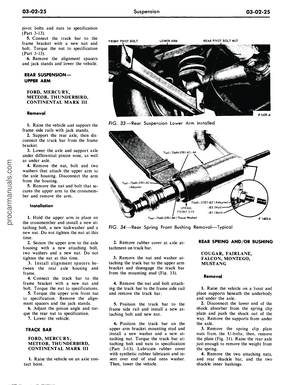 101
101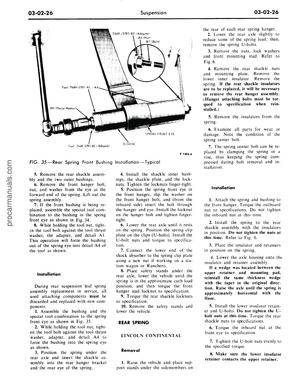 102
102 103
103 104
104 105
105 106
106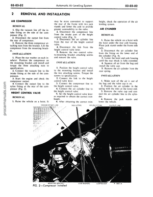 107
107 108
108 109
109 110
110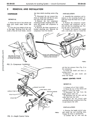 111
111 112
112 113
113 114
114 115
115 116
116 117
117 118
118 119
119 120
120 121
121 122
122 123
123 124
124 125
125 126
126 127
127 128
128 129
129 130
130 131
131 132
132 133
133 134
134 135
135 136
136 137
137 138
138 139
139 140
140 141
141 142
142 143
143 144
144 145
145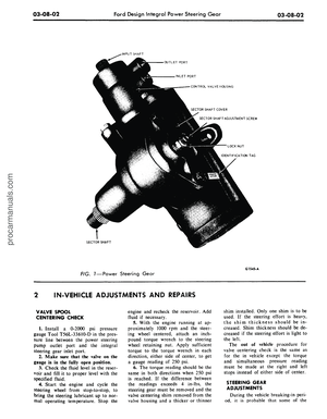 146
146 147
147 148
148 149
149 150
150 151
151 152
152 153
153 154
154 155
155 156
156 157
157 158
158 159
159 160
160 161
161 162
162 163
163 164
164 165
165 166
166 167
167 168
168 169
169 170
170 171
171 172
172 173
173 174
174 175
175 176
176 177
177 178
178 179
179 180
180 181
181 182
182 183
183 184
184 185
185 186
186 187
187 188
188 189
189 190
190 191
191 192
192 193
193 194
194 195
195 196
196 197
197 198
198 199
199 200
200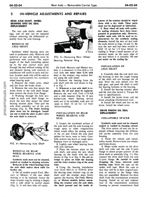 201
201 202
202 203
203 204
204 205
205 206
206 207
207 208
208 209
209 210
210 211
211 212
212 213
213 214
214 215
215 216
216 217
217 218
218 219
219 220
220 221
221 222
222 223
223 224
224 225
225 226
226 227
227 228
228 229
229 230
230 231
231 232
232 233
233 234
234 235
235 236
236 237
237 238
238 239
239 240
240 241
241 242
242 243
243 244
244 245
245 246
246 247
247 248
248 249
249 250
250 251
251 252
252 253
253 254
254 255
255 256
256 257
257 258
258 259
259 260
260 261
261 262
262 263
263 264
264 265
265 266
266 267
267 268
268 269
269 270
270 271
271 272
272 273
273 274
274 275
275 276
276 277
277 278
278 279
279 280
280 281
281 282
282 283
283 284
284 285
285 286
286 287
287 288
288 289
289 290
290 291
291 292
292 293
293 294
294 295
295 296
296 297
297 298
298 299
299 300
300 301
301 302
302 303
303 304
304 305
305 306
306 307
307 308
308 309
309 310
310 311
311 312
312 313
313 314
314 315
315 316
316 317
317 318
318 319
319 320
320 321
321 322
322 323
323 324
324 325
325 326
326 327
327 328
328 329
329 330
330 331
331 332
332 333
333 334
334 335
335 336
336 337
337 338
338 339
339 340
340 341
341 342
342 343
343 344
344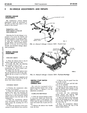 345
345 346
346 347
347 348
348 349
349 350
350 351
351 352
352 353
353 354
354 355
355 356
356 357
357 358
358 359
359 360
360 361
361 362
362 363
363 364
364 365
365 366
366 367
367 368
368 369
369 370
370 371
371 372
372 373
373 374
374 375
375 376
376 377
377 378
378 379
379 380
380 381
381 382
382 383
383 384
384 385
385 386
386 387
387 388
388 389
389 390
390 391
391 392
392 393
393 394
394 395
395 396
396 397
397 398
398 399
399 400
400 401
401 402
402 403
403 404
404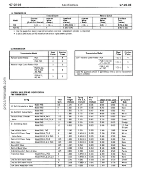 405
405 406
406 407
407 408
408 409
409 410
410 411
411 412
412