Page 193 of 413

04-01-06
General Axle Service
04-01-06
FLANGE BEARING
CUP RUNOUT
0.000
0.001
0.002
0.003
0.004
0.005
0.006
0.007
0.008
DRIVE SHAFT UNIVERSAL CROSS-SHAFT RUNOUT-INCH
0.000
0.000
0.001
0.002
0.003
0.004
0.005
0.006
0.007
0.008
0.001
0.001
0.0013
0.0022
0.0032
0.0042
0.0051
0.0061
0.0071
0.0081
0.002
0.002
0.0022
0.0027
0.0036
0.0045
0.0053
0.0062
0.0073
0.0082
0.003
0.003
0.0032
0.0037
0.0042
0.005
0.0058
0.0068
0.0075
0.0087
0.004
0.004
0.0042
0.0045
0.005
0.0057
0.0063
0.0072
0.0081
0.009
0.005
0.005
0.0051
0.0053
0.0058
0.0064
0.0071
0.0078
0.0087
0.0094
0.006
0.006
0.0061
0.0062
0.0067
0.0072
0.0078
0.0085
0.0093
0.010
0.007
0.007
0.0071
0.0072
0.0077
0.0081
0.0087
0.0092
0.0099
0.0104
0.008
0.008
0.0081
0.0082
0.0085
0.009
0.0094
0.010
0.0103
0.011
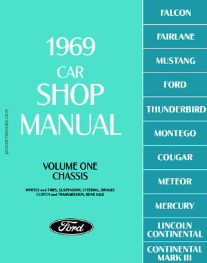
The total (combined) companion flange runout
is
located
in the
square where
the
columns containing
the
flange bearing cup runout
and universal cross shaft runout readings intersect.
FIG. 9—Companion Flange Combined Runout Chart
slightly moving the cross-shaft fore
and aft, then rotate the companion
flange from side-to-side.
8. With the indicator at zero, care-
fully retract the dial stem and rotate
the flange 180 degrees. Rotate the
cross-shaft 180 degrees on the flange
bearing cups to position the exposed
journal under the dial indicator adapt-
er. Rock the cross-shaft fore and aft
and the companion flange side-to-side
to establish the point at which the in-
dicator hand reverses direction. This
will determine the driveshaft universal
cross-shaft run-out. Record this read-
ing (Fig. 8).
9. Repeat steps 5 through 8 at least
three times and average the indicator
readings obtained (Fig. 7).
10.
To determine the total (com-
bined) companion flange runout, it
will be necessary to use the combined
runout chart (Fig. 9). Position a
straight edge at the amount of flange
bearing cup runout indicated on the
left hand column of the chart. Posi-
tion another straight edge vertically at
the amount of driveshaft universal
cross-shaft runout indicated on the top
of the chart. The point at which the
straight edges cross the chart indicates
the combined rear axle flange runout.
For example:
With an indicated 0.003 inch flange
bearing cup runout and an indicated
0.004 inch universal cross-shaft runout
(Fig. 9), the combined companion
flange runout will be 0.005 inch as in-
dicated in the square on the chart
(Fig. 9).
11.
If the reading obtained in Step
10 exceeds specifications, reposition
the companion flange 180 degrees on
the pinion shaft and repeat steps 1
through 10.
12.
If the repeat readings still ex-
ceed specifications, re-position the
flange an additional 90 degrees on the
pinion shaft and check the runout
(Steps 4 through 10).
13.
If the runout is still excessive,
replace the companion flange and
check the runout. If necessary, rotate
the new flange on the pinion shaft
until an acceptable runout is obtained.
If excessive runout is still evident
after replacement of the companion
flange, it will be necessary to replace
the ring and pinion gear, and repeat
the above checks until runout is within
specifications.
14.
Install the driveshaft assembly
(Group 5). Make sure the universal
joint bearing cups are properly posi-
tioned between the companion flange
lugs.
15.
Lower the vehicle. Road test
the vehicle. If drive shaft vibrations
are evident during the road test, re-
move the driveshaft from the compan-
ion flange and rotate it 180 degrees.
Road test the vehicle again.
THUNDERBIRD AND
CONTINENTAL MARK III
1.
Raise the vehicle on a hoist that
supports the rear axle (twin-post
hoist).
2.
Remove the driveshaft assembly
(Group 5).
3.
Check the companion flange for
damage.
4.
To check radial runout, set up
dial indicator as shown in Fig. 10.
5.
Rotate the companion flange
with the dial indicator in place. If the
runout exceeds specifications, remove
the flange and reinstall it 180 degrees
from original position. Follow the
procedure in Part 4-2 for companion
flange installation.
6. If the runout is still excessive, re-
move and reinstall the flange an addi-
tional 90 degrees and recheck runout.
7.
To check lateral (face) runout,
set up the dial indicator as shown in
Fig. 11. Repeat steps 5 and 6.
FLANGE
MOUNT HERE
Too/-4207-C
Too/-6565 USED WITH BRACKET FROM Tool-4201
FIG. 10—Checking Companion Flange Radial Runout—
Thunderbird and Continental Mark III
E1697-Aprocarmanuals.com
Page 194 of 413

04-01-07
General Axle Service
04-01-07
Tool-4201-
C
Tool-6565 USED WITH BRACKET
FROM Too/^*207-C
FLANGE
E1743-A
procedure under Backlash and Differ-
ential Bearing Preload Adjustments.
If the tooth pattern indicates a change
in shim thickness, follow the proce-
dure under Pinion Location.
REMOVABLE CARRIER
TYPE AXLE
The shim location for the removable
carrier type axle is between the pinion
retainer and the carrier (Fig. 13).
When adjusting this type carrier re-
ducing shim thickness will move the
pinion toward the ring gear; increas-
ing shim thickness will move the pi-
nion away from the ring gear (Fig.
13).
FIG. 11—Checking Companion Flange Lateral Runout—
Thunderbird and Continental Mark III
INTEGRAL CARRIER
TYPE AXLE
8. If the runout is still excessive, re-
place the companion flange and check
the runout. If necessary, rotate the
new flange on the pinion shaft until an
acceptable runout is obtained.
If excessive runout is still evident
after replacement of the companion
flange, it will be necessary to replace
the ring and pinion gear, and repeat
the above checks until runout is within
specifications.
9. Install the driveshaft assembly
(Group 5).
PINION LOCATION
ADJUSTMENT
BACKLASH
ADJUSTMENT,
LEFT
ADJUSTING
NUT
E1476-A
FIG. 12—Pinion and Ring Gear
Tooth Contact Adjustment
—
Integral Carrier Type Axles
PINION AND RING GEAR
TOOTH CONTACT
ADJUSTMENT
Two separate adjustments affect pin-
ion and ring gear tooth contact.
They are pinion location and backlash
(Figs.
12 and 13).
Individual differences in matching
the differential housing and the gear
set require the use of shims to locate
the pinion for correct contact with the
ring gear.
When adjusting either type axle,
shim thickness should be increased or
reduced only as indicated by the tooth
pattern check described in the fore-
going Section 1.
If the tooth pattern check indicates
a change in backlash only, follow the
PINION
LOCATION
ADJUSTMENT
SHIMS
LEFT
ADJUSTING
NUT
RIGHT
ADJUSTING
BACKLASH NUT
ADJUSTMENT El 409-A
FIG. 13—Pinion and Ring Gear
Tooth Contact Adjustment—
Removable Carrier Axles
The shim location for the integral
carrier type axle, is between the pi-
nion gear and the pinion rear bearing
cone (Fig. 12). When adjusting this
type axle, increasing shim thickness
moves the pinion toward the ring
gear; reducing shim thickness moves
the pinion away from the ring gear
(Fig. 12).
BACKLASH AND DIFFERENTIAL
BEARING PRELOAD
ADJUSTMENTS (ALL AXLES)
On a Light-Duty (WER) Axle, it is
necessary to remove the rear axle
shafts prior to performing the adjust-
ment procedures. Refer to Rear Axle
Shaft Wheel Bearing and Oil Seal Re-
placement—Light-Duty (WER), Axle,
Part 4-4, Section 2.
To secure a more uniform control
of differential side bearing preload in
service repairs, a dial indicator set-up
such as shown in Fig. 12 is used.
In both types of axle (Fig. 11 and
12),
the ring gear is moved away from
or toward the pinion as described in
the following procedure.
1.
Remove the adjusting nut locks,
loosen the differential bearing cap
bolts,
then torque the bolts to 15 ft-lbs
on integral carrier type axle; 20 ft-lbs
on removable carrier type axles before
making adjustments.
2.
The left adjusting nut is on the
ring gear side of the carrier. The right
nut is on the pinion side. Loosen the
right nut until it is away from the cup.
Tighten the left nut until the ring gear
is just forced into the pinion with
0.000 backlash then rotate the pinion
several revolutions to be sure no bind-
ing is evident. (Recheck the right nutprocarmanuals.com
Page 195 of 413
 Tightening the left nut")
04-01-08
General Axle Service
04 01-08
Too/-T57L-4067-A
E 1595-A
FIG.
14
—Adjusting Side Bearing Preload—Typical
at this time to be sure that it is still
loose.) Tightening the left nut moves
the ring gear into the pinion to de-
crease backlash, and tightening the
right nut moves the ring gear away.
3.
Install a dial indicator as shown
in Fig. 14.
4.
Tighten the right nut until it first
contacts the bearing cup. Then pre-
load the bearings from 0.008-0.012
inch case spread. Rotate the pinion
gear several revolutions in each direc-
tion while the bearings are loaded, to
seat the bearings in their cups to be
sure no bind is evident. This step is
important.
5. Again loosen the right nut to re-
lease the pre-load. If there is any
backlash between the gears as shown
by the dial indicator,(Fig.l2 or Fig. 10
Part 4-4) tighten the left nut just en-
ough to remove this backlash. At this
time,
make sure that one of the slots
in the left nut is so located that the
lock can be installed without turning
the nut. Carefully, tighten the right
nut until it just contacts the cup.
6. Torque the differential cap bolts
to specification.
On integral carrier type axles, set a
preload of 0.008 to 0.012 inch case
spread for new bearings and 0.003 to
0.005 for the original bearings.
On removable carrier type axles,
the preload is 0.008 to 0.012 inch case
spread for new bearings and 0.005 to
0.008 for the original bearings. As
preload is applied from the right side,
the ring gear is forced away from the
pinion and usually results in the cor-
rect backlash.
7.
Measure the backlash on several
teeth around the ring gear. If the
measurements vary more than 0.003
inch (both integral and removable car-
rier) there is excessive runout in the
gears or their mountings, which must
be corrected to obtain a satisfactory
unit. If the backlash is out of specifi-
cation, loosen one adjusting nut and
tighten the oposite nut an equal a-
mount to move the ring gear away
from or toward the pinion. When
moving the adjusting nuts, the final
movement should always be made in a
tightening direction. For example, if
the left nut had to be loosened one
notch, loosen the nut two notches,
then tighten it one. This insures that
the nut is contacting the bearing cup,
and that the cup cannot shift after
being put in service. After all such ad-
justments, check to be sure that the
case spread remains as specified for
the new or original bearings used.
8. Again check the tooth contact
pattern. If the pattern is still incor-
rect, a change in pinion location (shim
thickness) is indicated.
PINION LOCATION
Removable Carrier Type Axle
1.
Remove the attaching bolts and
the pinion and bearing retainer assem-
bly from the carrier.
2.
Measure the original shim thick-
ness with a micrometer. Increase or
decrease the shim thickness as indicat-
ed by the tooth pattern check des-
cribed in Section 1.
3.
Replace the pinion retainer O-
ring (Fig. 39, Part 4-2). Coat the O-
ring with axle lubricant before install-
ing. Do not roll the O-ring into the
groove. Snap it into position.
4.
Being careful not to pinch the
O-ring, install the pinion and bearing
retainer assembly in the carrier with
the corrected shim pack.
Before installing the pinion and
bearing retainer assembly, determine
which type of gear set is being used.
The non-hunting and pantial non-
hunting types can be identified by the
paint timing marks on the gear teeth
(Fig. 51, Part 4-2). Part 4-5 can also
be referred to for identification.
If the gear set is of the non-hunting
or partial non-hunting type clean the
teeth on both the pinion and drive
gear so that the timing marks are vis-
ible.
Rotate the differential case and
ring gear assembly in the carrier until
the marked teeth on the ring gear are
opposite the pinion entry hole. Place
the assembly in the carrier so that the
marked tooth on the pinion indexes
between the marked teeth on the ring
gear (Fig. 51, Part 4-2).
In almost every case of improper
assembly (gear assembled out of time)
the noise level and probability of fai-
lure will be higher than they would be
with properly assembled gears.
When installing the hunting type
gear set (no timing marks), assemble
the pinion and retainer assembly into
the carrier without regard to the
matching on any particular gear teeth.
5.
Install the retainer-to-carrier
mounting bolts and torque to specifi-
cations.
6. Adjust the backlash between the
ring gear and pinion as outlined in the
foregoing procedures.
7.
Make a tooth pattern check. If
the pattern is still unsatisfactory, re-
peat this procedure changing the shim
thickness each time until a satisfactory
tooth pattern is obtained.
Integral Carrier Type Axle
1.
Remove the differential case and
the drive pinion from the carrier cast-
ing, and then remove the pinion bear-
ings as described under Removal of
Differential Case and Drive Pinion in
Section 4.
2.
Measure the original shim thick-
ness with a micrometer. Increase or
decrease the shim thickness as indicat-
ed by the tooth pattern check des-
cribed in the foregoing Section 1 and
shown in Fig. 4.
3.
Install the corrected shim pack
and the bearings on the pinion, and
then install the pinion and the differ-
ential case in the carrier casting as
outlined under Installation of Drive
Pinion and Differential Case in Sec-
tion 4 of Part 4-3.
4.
Adjust the backlash between the
ring gear and pinion as outlined in the
foregoing procedure.
5.
Make a tooth pattern check. If
the pattern is still unsatisfactory, re-
peat this procedure changing the shim
thickness each time until a satisfactory
tooth pattern is obtained.procarmanuals.com
Page 196 of 413

The differential case or carrier
should be inspected before any parts
are")
04-01-09
General Axle Service
04-01-09
CLEANING AND INSPECTION
INSPECTION BEFORE
DISASSEMBLY OF CARRIER
(ALL AXLES)
The differential case or carrier
should be inspected before any parts
are removed from it. These inspec-
tions can help to find the cause of the
trouble and to determine the correc-
tions needed.
Mount the carrier in the holding
fixture shown in Fig. 15. Wipe the lu-
bricant from the internal working
parts,
and visually inspect the parts
for wear or damage.
Tool-T57L-500-A
FIG. 15
— Bench
Fixture for
Carrier Overhaul—Typical
Rotate the gears to see if there is
any roughness which would indicate
damaged bearings or chipped gears.
Check the gear teeth for scoring or
signs of abnormal wear.
Set up a dial indicator (Fig. 16) and
check the backlash at several points
around the ring gear. Backlash should
be within specifications.
If no obvious defect is noted, check
the gear tooth contact.
To check the gear tooth contact,
paint the gear teeth with the special
compound furnished with each service
ring gear and pinion. A mixture that
is too wet will run and smear. Too dry
a mixture cannot be pressed out from
between the teeth.
As shown in Fig. 17, rotate the ring
gear (use a box wrench on the ring
gear attaching bolts for a lever) five
complete revolutions in both directions
or until a clear tooth contact pattern
is obtained.
DIFFERENTIAL BEARING
CAP BOLTS
E 1776-A
FIG. 76-Backlash Check-
Typical
E
1001 - C
FIG.
7
7—Checking Gear Tooth
Contact—Typical
Certain types of gear tooth contact
patterns on the ring gear indicate in-
correct adjustment. Noise caused by
incorrect adjustment can often be cor-
rected by readjusting the gears. Ac-
ceptable patterns and the necessary
corrections are explained under Tooth
Contact Pattern Check in Section I.
Gear tooth runout can sometimes
be detected by an erratic pattern on
the teeth. However, a dial indicator
should be used to measure the runout
of the back face of the ring gear as
shown in Fig. 18. If this runout ex-
ceeds specifications, disassemble the
carrier and replace necessary parts as
indicated in Part 4-2, Section 4 and
Part 4-3, Section 4.
1699-A
FIG. 18 -Checking Ring Gear
Runout—Typical
Loosen the differential bearing cap
bolts,
and then torque them to 25 ft-
lbs.
Remove the adjusting nut locks.
Carefully loosen one of the adjusting
nuts to determine if any differential
bearing preload remains. If any pre-
load remains, the differential bearings
may be re-used, provided they are not
pitted or damaged.
INSPECTION AFTER
DISASSEMBLY OF CARRIER
(ALL AXLES)
Thoroughly clean all parts. Syn-
thetic seals must not he cleaned, soak-
ed or washed in cleaning solvents.
Always use clean solvent when clean-
ing hearings. Oil the bearings im-
mediately after cleaning to prevent rust-
ing. Inspect the parts for defects.
Clean the inside of the carrier before
rebuilding it. When a scored gear set
is replaced, the axle housing should he
washed thoroughly and steam cleaned.
This can onl\ be done effectively if the
axle shafts and shaft seals are re-
moved from the housing. Inspect indi-
vidual parts as outlined below.
GEARS
Examine the pinion and ring gear
teeth for scoring or excessive wear.
Extreme care must he taken not to
damage the pilot hearing surface of
the pinion.procarmanuals.com
Page 197 of 413

04-01-10
General Axle Service
04-01-10
The pattern taken during disassem-
bly should be helpful in judging if
gears can be re-used. Worn gears can-
not be rebuilt to correct a noisy condi-
tion. Gear scoring is the result of ex-
cessive shock loading or the use of an
incorrect lubricant. Scored gears can-
not be re-used.
Examine the teeth and thrust surfa-
ces of the differential gears. Wear on
the hub of the differential gear can
cause a chucking noise known as
chuckle when the vehicle is driven at
low speeds. Wear of splines, thrust
surfaces, or thrust washers, can con-
tribute to excessive drive line back-
lash.
BEARING CUPS AND
CONE AND ROLLER
ASSEMBLIES
Check bearing cups for rings,
scores, galling, or excessively worn
wear patterns. Pinion cups must be
solidly seated. Check by attempting to
insert a 0.0015-inch feeler between
these cups and the bottoms of their
bores.
When operated in the cups, cone
and roller assemblies must turn with-
out roughness. Examine the roller
ends for wear. Step-wear on the roller
ends indicates the bearings were not
preloaded properly, or the rollers were
slightly misaligned.
If inspection reveals either a defec-
tive cup or a defective cone and roller
assembly, both parts should be re-
placed to avoid early failure.
DIFFERENTIAL BEARING
ADJUSTING NUTS
Temporarily install the bearing caps
and test the fit of the adjusting nuts in
their threads. The nuts should turn
easily when the caps are tightened to
25 ft-lbs. The faces of the nuts that
contact the bearing cups must be
smooth and square. Replace the nuts
or examine the threads in the carrier
if their fit is not proper. Be sure that
the bearing caps and adjusting nuts
are on the side they were machined to
fit. Observe the punch marks and
scribe marks made during disassem-
bly.
U-JOINT FLANGE
Be sure that the eai» of the flange
have not been damaged in removing
the drive shaft or in removing the
flange from the axle. The end of the
flange that contacts the front pinion
bearing inner race as well as the flat
surface of the pinion nut counterbore
must be smooth. Polish these surfaces
if necessary. Roughness aggravates
backlash noises and causes wear of
the flange and pinion nut with a resul-
tant loss in pinion bearing preload.
PINION RETAINER
Be sure that the pinion bearing cups
are seated. Remove any chips or burrs
from the mounting flange. Clean the
groove for the O-ring seal and all lu-
bricant passages. If the cups were re-
moved, examine the bores carefully.
Any nicks or burrs in these bores
must be removed to permit proper
seating of the cups.
CARRIER HOUSING
Make sure that the differential
bearing bores are smooth and the
threads are not damaged. Remove any
nicks or burrs from the mounting sur-
faces of the carrier housing.
DIFFERENTIAL CASE
Make sure that the hubs where the
bearings mount are smooth. Carefully
examine the differential case bearing
shoulders, which may have been dam-
aged when the bearings were removed.
The bearing assemblies will fail if they
do not seat firmly against the shoul-
ders.
Check the fit (free rotation) of
the differential side gears in their
counterbores. Be sure that the mating
surfaces of the two parts of the case
are smooth and free from nicks or
burrs.
LIMITED SLIP AND
TRACTION-LOK
DIFFERENTIAL PARTS
Inspect the clutch plates for uneven
or extreme wear. The dog-eared clutch
plates must be free from burrs, nicks
or scratches which could cause excess-
ive or erratic wear to the bonding ma-
terial of the internally splined clutch
plates.
The internally splined clutch
plates should be inspected for condi-
tion of the bond, bonding material,
and wear. Replace the bonded plates
if their thickness is less than 0.085
inch or if the bonded material is
scored or badly worn. Inspect the
bonded plate internal teeth for wear.
Replace them, if excessive wear is evi-
dent. Bonded plates should be re-
placed as a set only
Examine all thrust surfaces and
hubs for wear. Abnormal wear on
these surfaces can contribute to a
noisy axle.
Inspect the Belleville spring (limited
slip) for proper free height of 1/4
inch.
LUBRICANT LEVEL
The lubricant level should be
checked every 6000 miles with the ve-
hicle in normal curb attitude. The lu-
bricant level should be at the lower
edge of the filler plug hole located in
either the carrier casting or housing
cover. It is unnecessary to periodically
drain the axle lubricant. The factory
fill should remain in the housing for
the life of the vehicle, except when re-
pairs are made. The specified lubri-
cant should be installed when the axle
is overhauled.procarmanuals.com
Page 198 of 413

Cleaning and Inspection
Removal and")
04-02-01
Rear Axle
—
Removable Carrier Type
04-02-01
PART
4-2
Rear Axle—Removable Carrier Type
COMPONENT INDEX
AXLE HOUSING (Coil Spring Suspension)
Cleaning and Inspection
Removal and Installation
AXLE HOUSING (Leaf Spring Suspension)
Cleaning and Inspection
Removal and Installation
AXLE SHAFT
Cleaning and Inspection
Removal and Installation
CONVENTIONAL DIFFERENTIAL
Cleaning and Inspection
Disassembly and Overhaul
Removal and Installation
DIFFERENTIAL BEARINGS AND RING
GEAR
Adjustment
Cleaning and Inspection
Removal and Installation
DIFFERENTIAL CARRIER
Cleaning and Inspection
Disassembly and Overhaul
Removal and Installation
LIMITED SLIP DIFFERENTIAL
Cleaning and Inspection
Description
Disassembly and Overhaul
Removal and Installation
PILOT BEARING
Cleaning and Inspection
Removal and Installation
PINION AND RING GEAR
Cleaning and Inspection
Removal and Installation
PINION BEARING
Cleaning and Inspection
Removal and Installation
PINION BEARING RETAINER
Cleaning and Inspection
Removal and Installation
PINION SPACER (Collapsible)
Removal and Installation
PINION OIL SEAL
Removal and Installation
MODEL APPLICATION
All
Models
01-10
02-04
01-10
02-13
02-08
02-19
01-10
02-19
01-10
02-13
02-08
01-10
02-03
02-13
02-13
01-10
02-15
01-10
02-15
01-10
02-15
01-10
02-15
02-04
J
01-09
02-08
N/A
N/A
02-17
Mercury
01-09
02-08
N/A
N/A
N/A
Meteor
01-09
02-08
N/A
N/A
02-17
Cougar
N/A
N/A
01-09
02-11
02-17
Fairlane
N/A
N/A
01-09
02-11
02-17
Falcon
N/A
N/A
01-09
02-11
02-17
Montego
N/A
N/A
01-09
02-11
02-17
Mustang
N/A
N/A
01-09
02-11
02-17
Lincoln-
Continental
N/A
N/A
01-09
02-11
N/A
Thunderbird
01-09
02-08
N/A
N/A
N/A
Continental-
Mark
III
01-09
02-08
N/A
N/A
N/A
A page number indicates that the item is
for
the vehicle listed
at
the head
of
the column.
N/A indicates that the item is not applicable
to
the vehicle listed.
procarmanuals.com
Page 199 of 413

Determining Spacer Size
Removal and Installation
REAR WHEEL BEARINGS AND SEALS
Cleaning and Inspec")
04-02-02
Rear Axle — Removable Carrier Type
04-02-02
COMPONENT INDEX
PINION SPACER (Solid)
Determining Spacer Size
Removal and Installation
REAR WHEEL BEARINGS AND SEALS
Cleaning and Inspection
Removal and Installation
TRACTION-LOK DIFFERENTIAL
Cleaning and Inspection
Description
Disassembly and Overhaul
Removal and Installation
U-JOINT FLANGE
Cleaning and Inspection
Removal and Installation
MODEL APPLICATION
All
Models
02-18
02-18
01-10
02-04
01-10
02-07
Ford
N/A
N/A
N/A
N/A
Mercury
N/A
N/A
N/A
N/A
Meteor
N/A
N/A
N/A
JN/A
Cougar
01-10
02-03
02-22
02-13
Fairlane
01-10
02-03
02-22
02-13
Falcon
01-10
02-03
02-22
02-13
Montego
01-10
02-03
02-22
02-13
Mustang
01-10
02-03
02-22
02-13
Lincoln-
Continental
N/A
02-03
N/A
N/A
Thunderbird
N/A
N/A
N/A
N/A
Continental-
Mark
III
N/A
N/A
N/A
N/A
A page number indicates that the item is for the vehicle listed at the head of the column.
N/A indicates that the item is not applicable to the vehicle listed.
1 DESCRIPTION
CONVENTIONAL AXLE
The rear axle is of the banjo-
housing, hypoid gear type using an 8
3/4, 9 or 9 3/8 inch ring gear, in
which the centerline of the pinion is
mounted below the centerline of the
ring gear (Fig. 1).
The pinion gear and the pinion
bearings are assembled in a pinion re-
tainer, which is bolted to the carrier.
The pinion is straddle mounted; that
LEFT AXLE SHAFT
4235
DRIVE PINION
4209
TAPERED ROLLER
BEARINGS 4621
SEAL - 4676
FIG.
1
—
Rear
Axle Assembly—Integral Pinion Gear and Shaft—8-3/4, 9, or 9-3/8 Inch Ring Gear—Typical
procarmanuals.com
Page 200 of 413

04-02-03
Rear Axle — Removable Carrier Type
04-02-03
is,
it is supported by bearings both in
front of and to the rear of the pinion
gear. Two opposed tapered roller
bearings support the pinion shaft in
front of the pinion gear with a col-
lapsible spacer for 8-3/4 inch or 9
inch ring gear, and a solid spacer used
with the 9 3/8 inch ring gear. A
straight roller (pilot) bearing supports
the pinion shaft at the rear of the pi-
nion gear. Pinion and ring gear tooth
contact is adjusted by adding or re-
moving shims from between the pinion
retainer and the carrier housing.
The differential assembly is mount-
ed on two opposed tapered roller
bearings, which are retained in the
carrier by removable caps. The entire
carrier assembly is bolted to the axle
housing.
Ball bearing assemblies (rear wheel
bearings) are pressed onto the outer
ends of the axle shafts and set in the
outer ends of the axle housing. These
bearings support the semi-floating
axle shafts at the outer ends. The
inner ends of the shafts spline to the
differential side gears. Bearing retain-
er plates hold the shafts in the hous-
ing. The left and right axle shafts are
not interchangeable, the left shaft
being shorter than the right.
CASE
COVER
BELLEVILLE
SPRING
CLUTC
HUB
STEEL
PLATES
BONDED
PLATES
E1741-A
FIG. 2—Limited-Slip Differential
LIMITED-SUP DIFFERENTIAL
The axle assembly, except for the
differential case and its internal com-
ponents, is identical to the convention-
al axle.
A constant-friction locking differen-
tial,
which employs clutch plates to
control differential action, is available
as optional equipment (Fig. 2).
Four steel clutch plates are locked
into the differential cover. Three
bronze, bonded clutch plates are
splined to a clutch hub which, in turn,
is splined to the left axle shaft. A
Belleville spring washer maintains a
constant pressure between the steel
and bonded clutch plates so that the
clutch is always engaged.
TRACTION-LOK
DIFFERENTIAL
The Traction-Lok (torque sensitive)
locking differential (Fig. 3) employs a
multiple disc clutch to control differ-
ential action. Shim(s), which control
side gear mounting distance, four
steel, four friction and one composite
plate (steel on one side and friction
material on the other) stacked on a
clutch hub, and four ear guides are
housed in the differential cover. Lo-
cated in the differential case between
the side gears is a one-piece pre-load
plate and block (four-pinion) and four
calibrated pre-load springs, which
apply an initial force to the clutch
pack. Additional clutch capacity is
derived from the side gear thrust
loads.
The four friction plates are
splined to the clutch hub which in turn
is splined to the left axle shaft, and
the eared steel plates are dogged to
the case; thus, the clutch is always en-
gaged.
PINION SHAFT
4211
PINION SHAFT
RETAINING PINS
359475-S
DIFFERENTIAL
CASE-4204
CASE-TO-COVER
RETAINING SCREWS
50025-S2
SIDE GEAR
THRUST WASHER
4228
CENTER BLOCK
(SHORT PINION PINION
SHAFT SEAT) SHAFT
4420 44207
7
PINION GEAR
THRUST WASHER
4230
PINION GEARS
4215
PINION GEAR
THRUST WASHER
4230
PINION SHAFT
44207
SHIM(S)
(AS REQ'D.)
4A324
DIFFERENTIAL
CASE COVER
4204
PINION GEAR
THRUST WASHER
4230
PRE-LOAD SPRING
PINION GEAR PLATE-4A326
THRUST WASHER
4230
CLUTCH PLATE
EAR GUIDES
(4)
4A323
E 1896-A
FIG. 3—Traction-Lok Differentialprocarmanuals.com
 1
1 2
2 3
3 4
4 5
5 6
6 7
7 8
8 9
9 10
10 11
11 12
12 13
13 14
14 15
15 16
16 17
17 18
18 19
19 20
20 21
21 22
22 23
23 24
24 25
25 26
26 27
27 28
28 29
29 30
30 31
31 32
32 33
33 34
34 35
35 36
36 37
37 38
38 39
39 40
40 41
41 42
42 43
43 44
44 45
45 46
46 47
47 48
48 49
49 50
50 51
51 52
52 53
53 54
54 55
55 56
56 57
57 58
58 59
59 60
60 61
61 62
62 63
63 64
64 65
65 66
66 67
67 68
68 69
69 70
70 71
71 72
72 73
73 74
74 75
75 76
76 77
77 78
78 79
79 80
80 81
81 82
82 83
83 84
84 85
85 86
86 87
87 88
88 89
89 90
90 91
91 92
92 93
93 94
94 95
95 96
96 97
97 98
98 99
99 100
100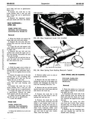 101
101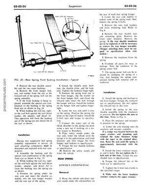 102
102 103
103 104
104 105
105 106
106 107
107 108
108 109
109 110
110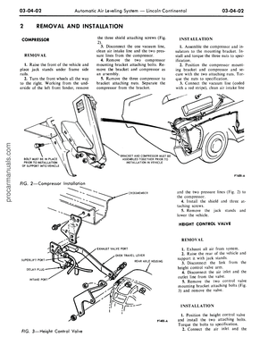 111
111 112
112 113
113 114
114 115
115 116
116 117
117 118
118 119
119 120
120 121
121 122
122 123
123 124
124 125
125 126
126 127
127 128
128 129
129 130
130 131
131 132
132 133
133 134
134 135
135 136
136 137
137 138
138 139
139 140
140 141
141 142
142 143
143 144
144 145
145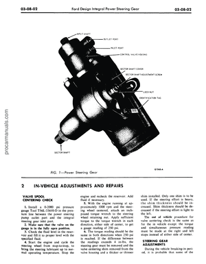 146
146 147
147 148
148 149
149 150
150 151
151 152
152 153
153 154
154 155
155 156
156 157
157 158
158 159
159 160
160 161
161 162
162 163
163 164
164 165
165 166
166 167
167 168
168 169
169 170
170 171
171 172
172 173
173 174
174 175
175 176
176 177
177 178
178 179
179 180
180 181
181 182
182 183
183 184
184 185
185 186
186 187
187 188
188 189
189 190
190 191
191 192
192 193
193 194
194 195
195 196
196 197
197 198
198 199
199 200
200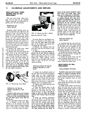 201
201 202
202 203
203 204
204 205
205 206
206 207
207 208
208 209
209 210
210 211
211 212
212 213
213 214
214 215
215 216
216 217
217 218
218 219
219 220
220 221
221 222
222 223
223 224
224 225
225 226
226 227
227 228
228 229
229 230
230 231
231 232
232 233
233 234
234 235
235 236
236 237
237 238
238 239
239 240
240 241
241 242
242 243
243 244
244 245
245 246
246 247
247 248
248 249
249 250
250 251
251 252
252 253
253 254
254 255
255 256
256 257
257 258
258 259
259 260
260 261
261 262
262 263
263 264
264 265
265 266
266 267
267 268
268 269
269 270
270 271
271 272
272 273
273 274
274 275
275 276
276 277
277 278
278 279
279 280
280 281
281 282
282 283
283 284
284 285
285 286
286 287
287 288
288 289
289 290
290 291
291 292
292 293
293 294
294 295
295 296
296 297
297 298
298 299
299 300
300 301
301 302
302 303
303 304
304 305
305 306
306 307
307 308
308 309
309 310
310 311
311 312
312 313
313 314
314 315
315 316
316 317
317 318
318 319
319 320
320 321
321 322
322 323
323 324
324 325
325 326
326 327
327 328
328 329
329 330
330 331
331 332
332 333
333 334
334 335
335 336
336 337
337 338
338 339
339 340
340 341
341 342
342 343
343 344
344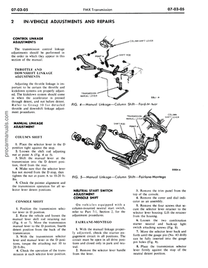 345
345 346
346 347
347 348
348 349
349 350
350 351
351 352
352 353
353 354
354 355
355 356
356 357
357 358
358 359
359 360
360 361
361 362
362 363
363 364
364 365
365 366
366 367
367 368
368 369
369 370
370 371
371 372
372 373
373 374
374 375
375 376
376 377
377 378
378 379
379 380
380 381
381 382
382 383
383 384
384 385
385 386
386 387
387 388
388 389
389 390
390 391
391 392
392 393
393 394
394 395
395 396
396 397
397 398
398 399
399 400
400 401
401 402
402 403
403 404
404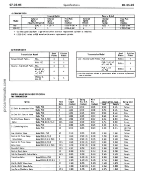 405
405 406
406 407
407 408
408 409
409 410
410 411
411 412
412