Page 121 of 413

03-05-08
Steering Columns And Linkage
03-05-08
tube.
In some instances the column
will shift into proper alignment when
the toe plate attaching nuts are loos-
ened. (Alignment is acceptable if a
.010 inch feeler blade can be passed
freely, completely around the area be-
tween the outer diameter of the steer-
ing shaft and the shift tube.) if the
misalignment condition can be attrib-
uted to this area, file or ream the dash
panel holes for greater clearance. If
the alignment is maintained after the
toe plate nuts and toe plate to column
clamp bolt and nut are torqued to the
8-12 ft-lb specification, no further ad-
justment is necessary.
4.
Remove instrument panel lower
trim panel. Vehicles equipped with a
combination radio stereo tape player
will require removal of the radio and
tape player assembly in order to gain
access to the upper R.H. steering col-
umn support bracket bolt.
5.
Loosen the seven bolts at the
steering column support bracket and
brake pedal support bracket.
6. Install a 3/16 inch diameter rod
spacer in the flex coupling to assure
proper clearance between upper and
lower steering shaft.
7.
Raise the vehicle, remove the
transmission splash shield, and visual-
ly align the column to center the
steering shaft in the column. Tighten
two toe plate attaching nuts sufficient-
ly to hold the column alignment (two
persons may be required for this oper-
ation).
8. Lower the vehicle.
9. Check the clearance between the
steering column support bracket and
the instrument panel bracket. It may
be necessary to add shims (Part Num-
ber MK-3054-A .060 inch thick, or
C3AZ-3054-A, .113 inch thick) be-
tween the support bracket and the in-
strument panel bracket to prevent
movement of the column when the
support bracket bolts are tightened.
10.
Loosen the two toe plate at-
taching nuts previously tightened. Re-
check steering column alignment. In
some instances it may be necessary to
enlarge the holes in the dash panel in
order to obtain proper column align-
ment.
11.
With the column properly al-
igned, torque the four toe plate at-
taching nuts to 4-9 ft-lbs.
12.
Torque the toe plate to steering
column clamp bolt to 3-5 ft-lbs.
13.
Recheck steering shaft to shift
tube alignment. A 0.10 inch feeler
blade should pass freely, completely
around the area between the outer di-
ameter of the steering shaft and shift-
er tube.
14.
Raise the vehicle.
15.
Adjust transmission shift link-
age.
16.
Install transmission splash
shield.
17.
Lower the vehicle.
18.
Install the radio stereo tape
player if so equipped.
19.
Install instrument panel lower
trim panel.
20.
Connect the battery.
REMOVAL AND INSTALLATION
STEERING COLUMN
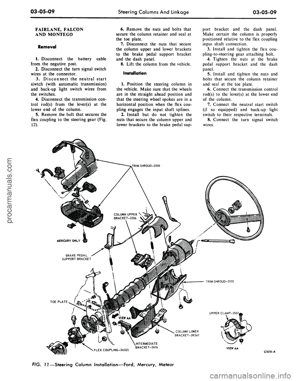
FORD, MERCURY, METEOR
Removal
1.
Disconnect the battery cable
from the negative post.
2.
Disconnect the turn signal switch
wires at the connector.
3.
Disconnect the neutral start
switch and back-up light switch wires
from the switches.
4.
Disconnect the transmission con-
trol rod(s) from the lever(s) at the
lower end of the column.
5.
Remove the bolt that secures the
flex coupling to the steering gear.
6. Remove the nuts that secure the
column retainer and seal at the toe
plate (Fig. 11).
7.
Ford, Meteor: Remove the two
screws that secure the lower trim
shroud to the upper trim shroud. Re-
move the two shrouds.
Mercury: Remove the two screws
that secure the lower trim shroud to
the upper trim shroud. Remove the
top shroud Disconnect the ignition
switch light bulb. Remove the ignition
and light switch bezels and spring clip
and remove the lower shroud. Discon-
nect the light switch electrical connec-
tor block.
8. Remove the two screws that se-
cure the intermediate bracket to the
column lower bracket.
9. While supporting the steering
column, remove the two nuts that se-
cure the column lower bracket to the
instrument panel. Remove the brack-
ets.
10.
Lift the steering column and
wheel from the vehicle.
Installation
1.
Position the steering column in
the vehicle. Index the block tooth on
the steering gear shaft with the corre-
sponding slot on the flex coupling. In-
stall and tighten the flex coupling-
to-steering gear attaching bolt.
2.
Place the column upper bracket
and column lower bracket in position
on the column and install but do not
tighten the four attaching nuts.
3.
Install and tighten the two nuts
that secure the column lower bracket
to the instrument panel. Make certain
the column is properly positioned rela-
tive to the flex coupling input shaft
connection.
4.
Install and tighten the screws
that secure the intermediate bracket to
the column lower bracket.
5.
Tighten the four attaching nuts
at the upper and lower brackets and
the two nuts at the upper bracket to
instrument panel. The dial pointer (if
so equipped) should be adjusted to
coincide with the selector lever.
6. Install and tighten the nuts and
bolts that secure the column retainer
and seal at the toe plate. Make sure
the steering shaft is centered in the
column before tightening the nuts.
7.
Ford, Meteor: Install and tighten
the two screws that secure the lower
trim shroud to the upper trim shroud.
Mercury: Connect the light switch
harness block. Install the ignition and
light switch bezels. Connect the igni-
tion switch light bulb. Install the top
shroud and the two screws that secure
the lower trim shroud to the upper
shroud.
8. Connect the transmission control
rod(s) to the lever(s) at the lower end
of the column.
9. Connect the neutral start switch
and back-up light switch to their re-
spective terminals.
10.
Connect the turn signal switch
wires.
11.
Connect the negative battery
cable to the battery.
12.
Check the operation of the
steering tilt mechanism if so equipped
and the switches.procarmanuals.com
Page 122 of 413

03-05-09
Steering Columns And Linkage
03-05-09
FAIRLANE, FALCON
AND MONTEGO
Removal
1.
Disconnect the battery cable
from the negative post.
2.
Disconnect the turn signal switch
wires at the connector.
3.
Disconnect the neutral start
siwtch (with automatic transmission)
and back-up light switch wires from
the switches.
4.
Disconnect the transmission con-
trol rod(s) from the lever(s) at the
lower end of the column.
5.
Remove the bolt that secures the
flex coupling to the steering gear (Fig.
12).
6. Remove the nuts and bolts that
secure the column retainer and seal at
the toe plate.
7.
Disconnect the nuts that secure
the column upper and lower brackets
to the brake pedal support bracket
and the dash panel.
8. Lift the column from the vehicle.
Installation
1.
Position the steering column in
the vehicle. Make sure that the wheels
are in the straight ahead position and
that the steering wheel spokes are in a
horizontal position when the flex cou-
pling engages the input shaft splines.
2.
Install but do not tighten the
nuts that secure the column upper and
lower brackets to the brake pedal sup-
port bracket and the dash panel.
Make certain the column is properly
positioned relative to the flex coupling
inpui shaft connection.
3.
Install and tighten the flex cou-
pling-to-steering gear attaching bolt.
4.
Tighten the nuts at the brake
pedal support bracket and the dash
panel.
5.
Install and tighten the nuts and
bolts that secure the column retainer
and seal at the toe plate.
6. Connect the transmission control
rod(s) to the lever(s) at the lower end
of the column.
7.
Connect the neutral start switch
(if so equipped) and back-up light
switch to their respective terminals.
8. Connect the turn signal switch
wires.
COLUMN UPPER \
BRACKET-3506 V
BRAKE PEDAL
SUPPORT BRACKET
TRIMSHROUD-3530
UPPER CLAMP-3507,
COLUMN LOWER
BRACKET-3R547
•
FLEXCOUPLING-3A525
^INTERMEDIATE
BRACKET-3676
VIEW AA
G1616-A
FIG. 11—Steering Column Installation—Ford, Mercury, Meteorprocarmanuals.com
Page 123 of 413

03-05-10
Steering Columns And Linkage
03-05-10
9. Connect the battery cable to the
negative post.
10.
Check the operation of the
switches.
COUGAR, MUSTANG
Removal
cable
1.
Disconnect the battery
from the negative post.
2.
Disconnect the turn signal switch
wires at the connector.
3.
On tilt-away columns, disconnect
the tilt-control cable from the vacuum
motor and mounting bracket.
4.
Remove the bolt that secures the
flex coupling to the steering gear.
5.
Remove the nuts and bolts that
secure the column retainer and seal at
the toe plate.
6. Remove the nuts that secure the
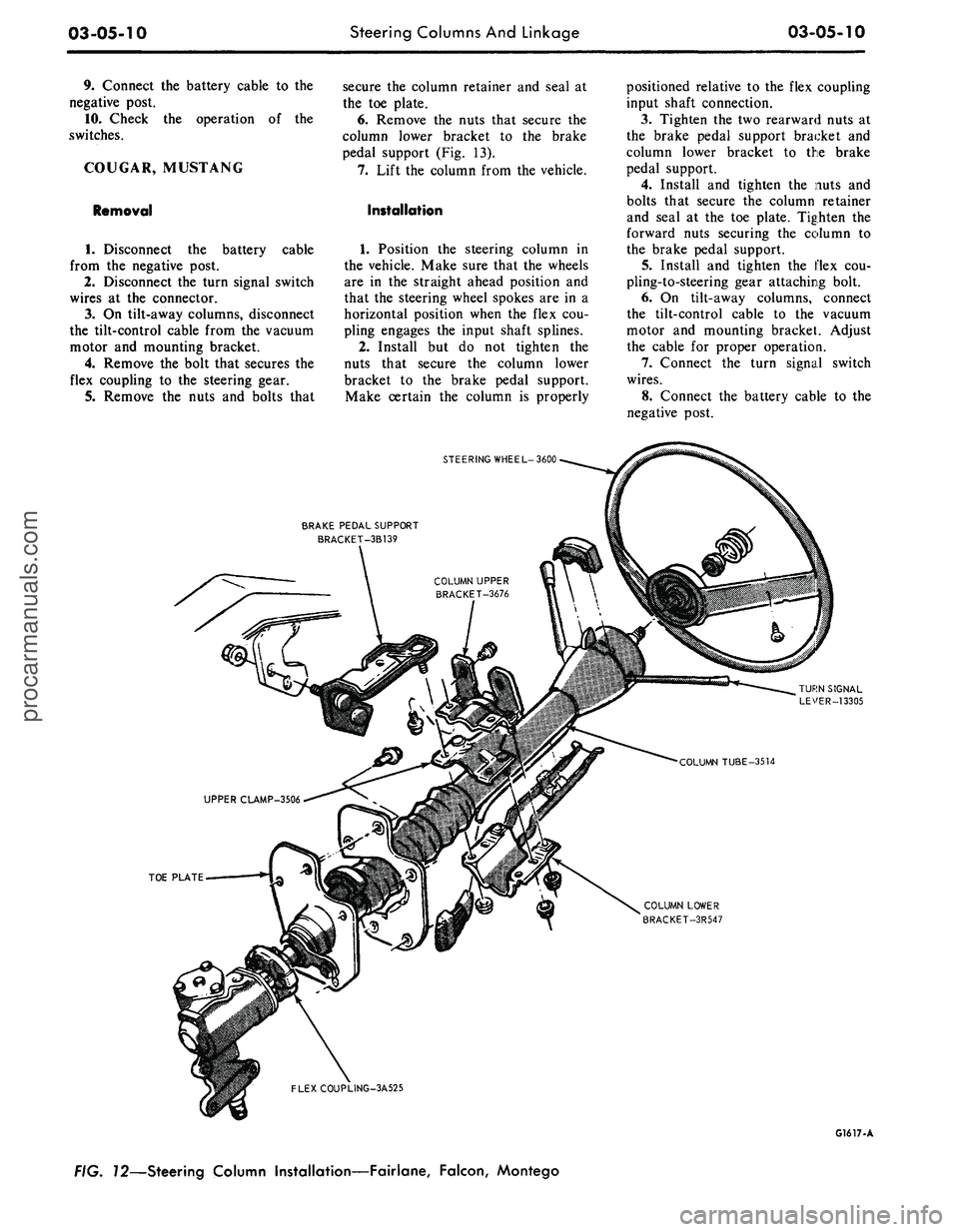
column lower bracket to the brake
pedal support (Fig. 13).
7.
Lift the column from the vehicle.
Installation
1.
Position the steering column in
the vehicle. Make sure that the wheels
are in the straight ahead position and
that the steering wheel spokes are in a
horizontal position when the flex cou-
pling engages the input shaft splines.
2.
Install but do not tighten the
nuts that secure the column lower
bracket to the brake pedal support.
Make certain the column is properly
positioned relative to the flex coupling
input shaft connection.
3.
Tighten the two rearward nuts at
the brake pedal support bracket and
column lower bracket to the brake
pedal support.
4.
Install and tighten the nuts and
bolts that secure the column retainer
and seal at the toe plate. Tighten the
forward nuts securing the column to
the brake pedal support.
5.
Install and tighten the flex cou-
pling-to-steering gear attaching bolt.
6. On tilt-away columns, connect
the tilt-control cable to the vacuum
motor and mounting bracket. Adjust
the cable for proper operation.
7.
Connect the turn signal switch
wires.
8. Connect the battery cable to the
negative post.
STEERING WHEEL-3600
BRAKE PEDAL SUPPORT
BRACKET-3B139
TOE PLATE
COLUMN LOWER
BRACKET-3R547
FLEXCOUPLING-3A525
G1617-A
FIG. 72—Steering Column Installation—Fairlane, Falcon, Montegoprocarmanuals.com
Page 124 of 413

03-05-11
Steering Columns
And
Linkage
03-05-11
9. Check
the
operation
of the
steer-
ing tilt mechanism
(if so
equipped)
and
the
switches.
THUNDERBIRD
AND
CONTINENTAL MARK
III
Removal
1.
Remove
the
instrument panel
lower outer finish panel, instrument
panel steering column plate
and
cover.
2.
Disconnect
the
negative cable
from
the
battery.
3.
Remove
the
bolt that attaches
the flexible coupling
to the
steering
shaft.
4.
Disconnect
the
shift
rod
from
the
lever
at the
lower
end of the
column.
5.
Remove
the
four screws that
at-
tach
the
column retainer
to the
dash
panel.
6. Working from
the
underside
of
the instrument panel disconnect
the
steering column tilt-control cable from
the vacuum motor
and
mounting
bracket
(if so
equipped)
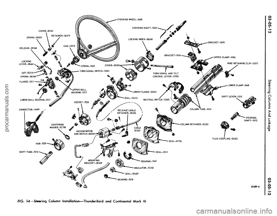
(Fig. 14).
7.
Disconnect
the
turn signal
switch,
and
emergency flasher wires
at
the connectors. Disconnect
the
wires
from
the
neutral start switch.
8. While supporting
the
steering
column, remove
the
four bolts that
at-
tach
the
lower clamp
to the
upper
clamp
(Fig. 14).
Lift
the
column from
the vehicle.
Installation
1.
Position
the
column
in the
vehi-
cle making sure that
the
steering shaft
engages
the
flex coupling.
1.
Install
the
column retainer-
to-dash panel attaching screws,
but do
not tighten them.
3.
Install
the
lower clamp
and the
attaching nuts. Tighten
the
nuts fing-
ertight.
4.
Move
the
lower flange
as re-
quired
to
center
the
steering shaft
in
the tube. Aligning procedures
are de-
tailed
in
Part
3-1.
Tighten
the
lower
flange attaching nuts when
the
shaft
is
centered.
5.
Connect
the
shift
rod to the
shift
lever
at the
lower
end of the
column.
6. Install
and
tighten
the
flex
cou-
pling attaching bolt.
7.
Tighten
the
instrument panel-
to-clamp attaching nuts.
BRAKE PEDAL SUPPORT
STEERING WHEEL-3600
TURN SIGNAL LEVER-13305
COLUMN TUBE-3514
COLUMN LOWER BRACKET-3R547
•TOE PLATE
FLEX COUPLING-3A525
G1618-A
f/G.
73—Steering Column Installation—Cougar, Mustangprocarmanuals.com
Page 125 of 413
SPRING-3D655
RELEASE-3D544
BRACKET-3678
UPPER CLAMP-3506
WIRE RETAINING CLIP-13377
SPRING-3520 COVER-3D505
TURN SIGNAL SWITCH-13341
TURN SIGNAL AND TILT
CONTROL LEVER-13305
FLEX COUPLING-3A525
BEARING-7347
INSULATOR-7C102
SEAL-3E629
BEARING-3576
G1539-A
flG.
14—Steering
Column Installation—Thwderibird cmd Corrttnettfd Markprocarmanuals.com
Page 126 of 413
STEERING WHEEL-3600
STEERING SHAFT-3525
LOWER CLAMP
3668
CENTERING WASHER-3C708
G1542-A
:/G.
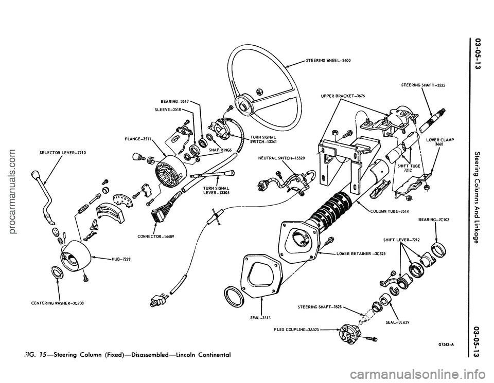
15—Steering Column (Fixed)—Disassembled—Lincoln Continentalprocarmanuals.com
Page 127 of 413

03-05-14
Steering Columns And Linkage
03-05-14
8. Connect the turn signal and
emergency flasher switch wires at the
multiple connectors. Connect the wires
to the neutral start switch. Adjust-
ments for the neutral start switch are
detailed in Group 7 of this manual.
9. Connect the tilt-column control
cable to the release cable retainer and
vacuum motor (if so equipped). To re-
move cable slack, loosen the bracket
attaching screw and pull it slightly
toward the column, then tighten the
screw. If difficulty in adjusting this
control is experienced, the retainer
slot may be filed to gain additional
travel.
10.
Install the instrument panel
steering column plate and cover and
the instrument panel lower outer fin-
ish panel.
11.
Connect the negative cable to
the battery.
12.
Start the engine and check the
operation of the steering column and
switches.
LINCOLN CONTINENTAL
Removal
1.
Disconnect the battery.
2.
Disconnect the rod from the
lever at the lower end of the selector
tube.
Loosen the clamp bolt that locks
the flexible coupling to the steering
shaft.
3.
Working from the underside of
the steering wheel spoke, remove the
two screws that secure the crash pad.
Remove the pad. Do not use a ham-
mer or knock-off type wheel puller.
Striking the puller or shaft may cause
damage to the bearings and/or col-
lapsible column. Remove the steering
wheel as shown in Fig. 15.
4.
Remove the instrument panel
steering column finish plate.
5.
Remove the four screws that at-
tach the lower retainer to the dash
panel.
6. Disconnect the turn signal switch
and emergency flasher wires at the
connectors. Disconnect the wires from
the neutral start switch.
7.
While supporting the steering
column, remove the bolts that attach
the lower clamp to the upper bracket
(Fig. 15). Lift the column from the ve-
hicle.
Installation
1.
Position the column in the vehi-
cle,
making sure that the steering
shaft engages the flex coupling.
2.
Install the column retainer-
to-dash panel attaching screws, but do
not tighten them.
3.
Install the lower clamp and the
attaching nuts. Tighten the nuts fing-
ertight.
4.
Move the lower flange as re-
quired to center the steering shaft in
the tube. Aligning procedures are de-
tailed in Part 3-1. Tighten the lower
flange attaching nuts when the shaft is
centered.
5.
Connect the shift rod to the shift
lever at the lower end of the column.
6. Install and tighten the flex cou-
pling attaching bolt.
7.
Tighten the instrument panel-
to-clamp attaching nuts.
8. Connect the turn signal and
emergency flasher switch wirss at the
multiple connectors. Connect the wires
to the neutral start switch. Adjust-
ments for the neutral start switch are
detailed in Group 7 of this manual.
9. Install the instrument panel
steering column finish plate.
10.
Install the steering wheel and
crash pad.
MAJOR REPAIR OPERATIONS
STEERING COLUMN
SHIFT TUBE REPLACEMENT
STATIONARY COLUMN
WITH STANDARD
TRANSMISSION
Removal
1.
Working from the underside of
the steering wheel spoke, remove the
two screws that secure the crash pad.
Remove the pad. (On Continental
Mark III models, pry out the crash
pad insert and remove the two screws
that secure the crash pad. Remove the
crash pad. On models equipped with
steering wheel mounted speed con-
trols,
refer to Group 16 for removal
instructions).
2.
Remove the steering wheel from
the steering shaft with tool T67L-
3600-A (Fig. 1). Then, remove the
tool from the steering wheel. Do not
use a knock-off type steering Wheel
puller or strike the end of the steering
shaft with a hammer. Striking the
puller or shaft will damage the bear-
ing or the collapsible column.
3.
Remove the steering column
from the vehicle.
4.
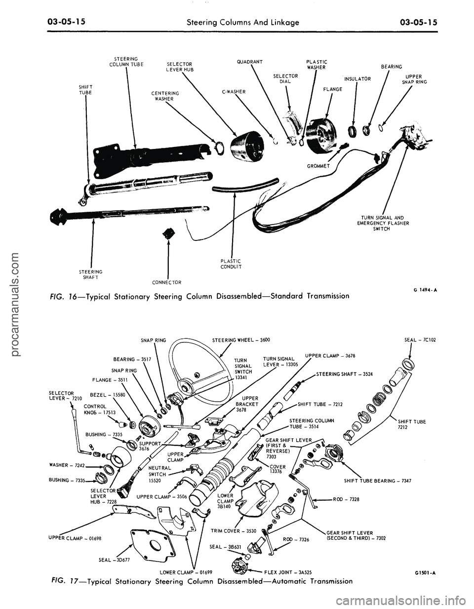
Remove the selector lever from
the hub (Fig. 16).
5.
Remove the bearing upper snap
ring. It may be necessary to pull the
turn signal switch out to remove the
snap ring.
6. Remove the screws that attach
the shift tube bearing, shift arms, and
shift tube to the lower end of the
steering column.
7.
Slip the shift tube and steering
shaft from the lower end of the steer-
ing column tube. The upper bearing
has a slight press fit on the steering
shaft.
8. Remove the C-washer from the
upper end of the steering shaft, and
pull the shift tube from the steering
shaft.
9. Remove the shift tube bearing
from the lower end of the tube
Installation
1.
Position the shift tube bearing
(Fig. 16) on the tube and insert the
steering shaft in the shift tube.
2.
Install the C-washer on the
upper end of the steering shaft.
3.
Insert the shift tube and steering
shaft into the steerint column tube
and install the three attaching screws
at the lower end of the steering col-
umn tube.
4.
Position the bearing and insula-
tor on the shaft if it was disturbed
during removal. Work it down onto
the shaft as far as possible, then place
a piece of 3/4 ID x 2 1/8 inch pipe
over the end of shaft and install the
steering wheel attaching nut (Fig. 2).
5.
Tighten the nut until the bearing
is seated in the flange, then remove
the nut and pipe from the shaft.
6. Position the turn signal switch
on the flange and install the three at-
taching screws. Install the upper snap
ring.
7.
Install the selector lever and the
turn signal lever in the column.
8. Adjust and install the neutral
start switch as detailed in Group 7.
9. Install the steering column in the
vehicle.procarmanuals.com
Page 128 of 413
03-05-15
Steering Columns And Linkage
03-05-15
SHIFT
TUBE
STEERING
COLUMN
TUBE
SELECTOR
I
LEVER
HUB
\
CENTERING
I
WASHER
QUADRANT
BEARING
UPPER
SNAP RING
TURN SIGNAL AND
EMERGENCY FLASHER
SWITCH
PLASTIC
CONDUIT
STEERING
SHAFT
CONNECTOR
FIG. 16—Typical Stationary Steering Column Disassembled—Standard Transmission
G 1494-A
SNAP RING
STEERING WHEEL-3600
SEAL - 7C102
BEARING -3517
SNAP RING
FLANGE -3511
SELECTOR BEZEL-
LEVER- 7210 ZtL
GEAR SHIFT LEVER
(FIRST
&
REVERSE)
/
7303
/ 9
WASHER - 7242
BUSHING - 733
- 7347
UPPER CLAMP-01698
GEARSHIFT LEVER
(SECOND & THIRD) - 7302
SEAL-
LOWER CLAMP - 01699
^^r**——
FLEX JOINT - 3A525
FIG. 17—Typical Stationary Steering Column Disassembled—Automatic Transmission
G1501-Aprocarmanuals.com