Page 281 of 413

06-03-02
Ford Design Four-Speed Transmission
06-03-02
1 DESCRIPTION
DESCRIPTION
The Ford designed 4-speed trans-
mission
(Fig. 1) is of the
fully
syn-
chronized type with
all
gears except
the reverse sliding gear being
in con-
stant mesh.
All
forward-speed changes
are accomplished with synchronizer
sleeves.
All forward-speed gears
in the
transmission
are
helical-type, however,
the reverse sliding gear
and the
exter-
ior
of the
first-and second-speed
syn-
chronizer sleeve
are
spur-type gears.
The specifications
of
this section Part
6-4 lists
the
transmission model
num-
bers
and
vehicles
in
which they
are
used.
C 1765-B
FIG. 7—Four-Speed Transmission—Typical
A transmission service identification
tag
is
located
on the
right side
of the
case
at the
front
(Fig. 2). The
first
line
on the tag
will show
the
transmis-
sion model
and
service identification
code when required.
The
second line
will show
the
transmission serial
num-
ber. Additionally,
a
driveline compo-
nent identification
tag is
attached
to
the upper right side
of the
transmis-
sion case.
TRANS.
MODEL
O
RUG-C-2
10001
O
SERIAL NO.
C 2088-A
FIG. 2—Transmission
Identification
Tag
IN-VEHICLE ADJUSTMENTS
AND
REPAIRS
SHIFT LINKAGE ADJUSTMENT
1.
Loosen
the
three shift linkage
adjustment nuts. Install
a 1/4
inch
di-
ameter alignment tool through
the
control bracket
and
lever holes
as
shown
in Fig. 13.
An alignment tool
can be
made
from
1/4
inch diameter drill
rod
bent
to
an "L"
shape.
The
extensions
should
be 2 1/2
inch
and 3 3/4
inch
from
the
elbow. Short
end of
align-
ment
pin
should
be
inserted into
con-
trol bracket
and
linkage holes until
it
bottoms.
2.
Disconnect
the
reverse gear shift
rod from
the
shift lever.
3.
Shift
the
transmission into
re-
verse gear.
4.
Tighten
the 1-2 and 3-4
shift
rod
adjustment nuts.
5.
Connect
the
reverse gear shift
rod
to the
shift lever. Shift
the
reverse
lever
to the
neutral position
and
tight-
en
the
adjustment
nut.
6. Remove
the
alignment
pin.
7.
Check
the
gear shift lever
for a
smooth crossover.
REMOVAL
AND
INSTALLATION
REMOVAL
1.
Raise
the
vehicle
on a
hoist.
2.
Mark
the
driveshaft
so
that
it
may
be
installed
in the
same relative
position. Disconnect
the
drive shaft
from
the
rear U-joint flange. Slide
the
drive shaft
off the
transmission output
shaft
and
install
the
extension housing
seal installation tool into the extension
housing
to
prevent lubricant leakage.
See
Fig. 2,
Part
6-1.
3.
Disconnect
the
speedometer
cable from
the
extension housing.
4.
Disconnect
the
parking brakeprocarmanuals.com
Page 282 of 413

06-03-03
Ford Design Four-Speed Transmission
06-03-03
cable from the equalizer lever and sep-
arate the lever from the crossmember.
5.
Remove the hairpin retainer se-
curing the cable to the transmission
rear support crossmember, and then
pull the cable assembly forward and
out of the crossmember.
6. Remove the retaining clip, flat
washer, and spring washer that se-
cures the shift rods to the shift levers.
7.
Remove the bolts that attach the
shift linkage control bracket to the ex-
tension housing and position the as-
sembly out of the way.
8. Support the engine with a trans-
mission jack and remove the extension
housing-to-engine rear support attach-
ing bolts.
9. Raise the rear of the engine high
enough to remove the weight from the
crossmember. Remove the bolts re-
taining the crossmember to the frame
side supports and remove the
crossmember.
10.
Support the transmission on a
jack and remove the bolts that attach
the transmission to the flywheel hous-
ing.
11.
Move the transmission and jack
rearward until the transmission input
shaft clears the flywheel housing. If
necessary, lower the engine enough to
obtain clearance for transmission re-
moval.
Do not depress the clutch pedal
while the transmission is removed.
INSTALLATION
1.
Make sure that the mounting
surface of the transmission and the
flywheel housing are free of dirt,
paint, and burrs. Install two guide
pins in the flywheel housing lower
mounting bolt holes. Move the trans-
mission forward on the guide pins
until the input shaft splines enter the
clutch hub splines and the case is posi-
tioned against the flywheel housing.
2.
Install the two upper transmis-
sion to flywheel housing, mounting
bolts snug, and then remove the two
guide pins. Install the two lower
mounting bolts. Torque all mounting
bolts to specifications.
3.
Raise the rear of the engine and
install the crossmember. Install and
torque the crossmember attaching
bolts to specifications, then lower the
engine.
4.
With the transmission extension
housing resting on the engine rear
support, install the transmission ex-
tension housing attaching bolts. Tor-
que the bolts to specifications.
5.
Position the shift linkage control
bracket to the extension housing and
install the attaching bolts.
6. Secure each shift rod to its re-
spective lever with the spring washer,
flat washer, and retaining pin.
7.
Guide the parking brake cable
assembly through the hole in the
transmission rear support crossmemb-
er. Secure the cable assembly to the
crossmember with the hair pin retain-
er.
8. Insert the parking brake front
cable in the equalizer and install the
equalizer in the bracket on the
crossmember. Secure the parking
brake rear cable to the equalizer.
9. Connect the speedometer cable
to the extension housing.
10.
Remove the extension housing
installation tool and slide the forward
end of the drive shaft over the trans-
mission output shaft. Connect the
drive shaft to the rear U-joint flange.
11.
Place both forward gear shift
levers and the reverse shift lever in the
neutral position and insert a 1/4 inch
diameter alignment tool in the shift
linkage alignment hole (Fig. 17). It
may be necessary to loosen the adjust-
ment nuts to install the alignment
tool. Adjust the linkage as necessary
and tighten the adjustment nuts to
specifications. Remove the alignment
tool.
12.
Fill the transmission to the
proper level with the specified lubri-
cant.
13.
Lower the car. Check tne shift
and crossover motion for full shift en-
gagement and smooth crossover oper-
ation.
MAJOR REPAIR OPERATIONS
DISASSEMBLY
1.
Mount the transmission in a
holding fixture and drain the lubri-
cant.
2.
Remove the cover attaching
screws from the case. Lift the cover
and gasket from the case.
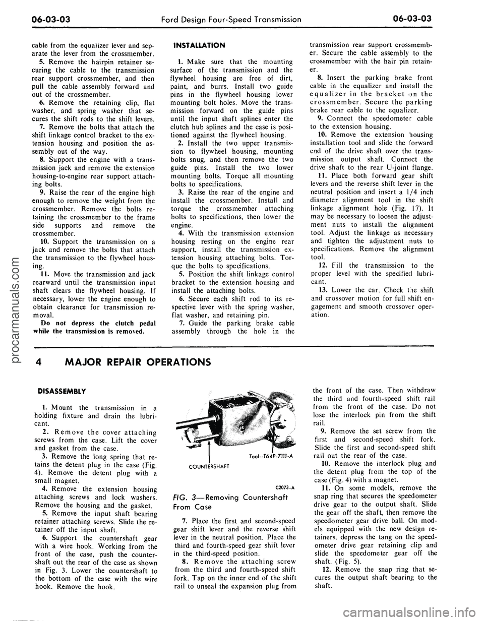
3.
Remove the long spring that re-
tains the detent plug in the case (Fig.
4).
Remove the detent plug with a
small magnet.
4.
Remove the extension housing
attaching screws and lock washers.
Remove the housing and the gasket.
5.
Remove the input shaft bearing
retainer attaching screws. Slide the re-
tainer off the input shaft.
6. Support the countershaft gear
with a wire hook. Working from the
front of the case, push the counter-
shaft out the rear of the case as shown
in Fig. 3. Lower the countershaft to
the bottom of the case with the wire
hook. Remove the hook.
Tool-T64P-711hA
COUNTERSHAFT
C2073-A
FIG. 3—Removing Countershaft
From Case
7.
Place the first and second-speed
gear shift lever and the reverse shift
lever in the neutral position. Place the
third and fourth-speed gear shift lever
in the third-speed position.
8. Remove the attaching screw
from the third and fourth-speed shift
fork. Tap on the inner end of the shift
rail to unseal the expansion plug from
the front of the case. Then withdraw
the third and fourth-speed shift rail
from the front of the case. Do not
lose the interlock pin from the shift
rail.
9. Remove the set screw from the
first and second-speed shift fork.
Slide the first and second-speed shift
rail out the rear of the case.
10.
Remove the interlock plug and
the detent plug from the top of the
case (Fig. 4) with a magnet.
11.
On some models, remove the
snap ring that secures the speedometer
drive gear to the output shaft. Slide
the gear off the shaft, then remove the
speedometer gear drive ball. On mod-
els equipped with the new design re-
tainers, depress the tang on the speed-
ometer drive gear retaining clip and
slide the speedometer gear off the
shaft. (Fig. 5).
12.
Remove the snap ring that se-
cures the output shaft bearing to the
shaft.procarmanuals.com
Page 283 of 413

06-03-04
Ford Design Four-Speed Transmission
06-03-04
13.
Remove the output shaft bear-
ing as shown in Fig. 6.
14.
Remove the input shaft and
bearing and the blocking ring from
the front of the case.
15.
Move the output shaft to the
right side of the case to provide clear-
ance for the shift forks. Rotate the
forks as shown in Fig. 7, then lift
them from the case.
16.
Support the thrust washer and
first-speed gear to prevent them from
sliding off the shaft, then lift the out-
put shaft assembly from the case as
shown in Fig. 8.
17.
Remove the reverse gear shift
fork set screw. Rotate the reverse shift
rail 90 degrees as shown in Fig. 9.
Slide the shift rail out of the rear of
the case. Lift the reverse shift fork
from the case.
18.
Remove the reverse detent plug
and spring from the case with a mag-
net.
19.
Remove the reverse idler gear
shaft from the case as shown in Fig.
10.
20.
Lift the reverse idler gear and
the thrust washers from the case. Be
careful not to drop the bearings and
the dummy shaft from the gear.
21.
Lift the countershaft gear and
the thrust washers from the case. Be
careful not to drop the bearings or the
dummy shaft from the counter-shaft
gear.
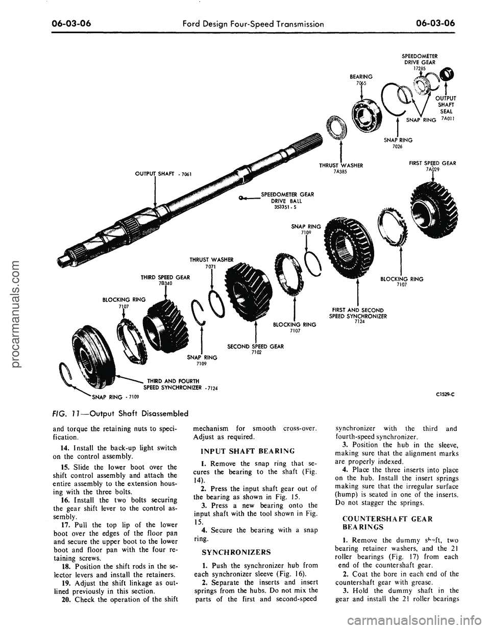
22.
Remove the snap ring from the
front of the output shaft. Slide the
third and fourth-speed synchronizer
(Fig. 11) blocking ring and the third-
speed gear off the shaft.
23.
Remove the next snap ring and
the second-speed gear thrust washer
from the shaft. Slide the second-speed
gear and the blocking ring off the
shaft.
24.
Remove the next snap ring.
25.
Remove the thrust washer, first
speed gear and blocking ring from the
rear of the shaft. The first and second
synchronizer hub is a press fit on the
output shaft. To eliminate the possi-
bility of damaging the synchronizer
assembly, remove the synchronizer
hub using an arbor press as shown in
Part 6-2, Fig. 20. Do not attempt to
remove or install the hub by hammer-
ing or prying.
PARTS REPAIR OR
REPLACEMENT
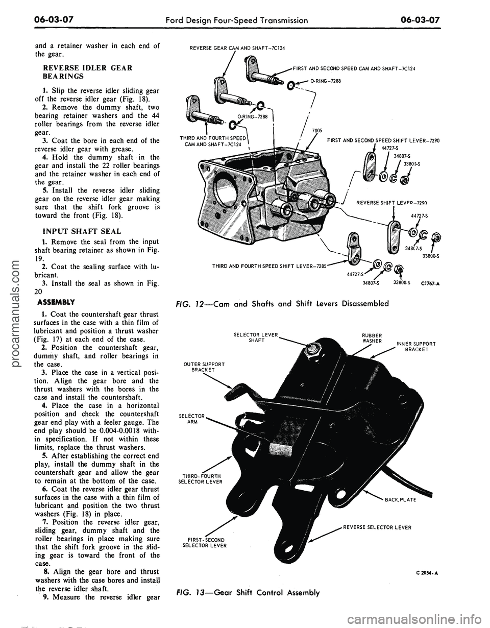
CAM AND
SHAFT SEALS
1.
Remove the attaching nut, lock
washer and the flat washer from each
shift lever and remove the three levers.
2.
Remove the three cam and shafts
from inside the case.
jjL
-SPRING
•
7234
if
Q-* 'DETENT PtUG 7C316
THIRD AND FOURTH
SPEED SHIFT FORK- 7230
SCREW. 377886 - S
DETENT PLUG-fr-fl
7C316 **
INTERLOCK PIN
7235
FIRST AND SECOND SPEED SHIFT RAIL
7240
fl-«-—
SCREW - 377386 • S
FIRST AND SECOND
SPEED SHIFT FORK • 7230
THIRD AND FOU
SPEED SHIFT RAIL
7241
EXPANSION
PLUG-74112-S
MAGNETIC DRAIN PLUG -373719-S
FIG. 4—Shift Rails and Forks Disassembled
C2074-A
SPEEDOMETER DRIVE
GEAR
SPRING CLIP
FRONT
C2052-A
# 5—Speedometer Drive Gear Installationprocarmanuals.com
Page 284 of 413

06-03-05
Ford Design Four-Speed Transmission
06-03-05
DETAIL
4
FORD
AND
MERCURY
DETAIL
5
COUGAR. FAIRLANE,
FALCON,
MONTEGO,
AND MUSTANG
REVERSE SHIFT
RAIL
C1533-B
FIG. 6—Removing Output Shaft Bearing
3.
Remove
and
discard
the
O-ring
from each
cam and
shaft (Fig.
12).
4.
Dip the new
Orings
in
gear
lu-
bricant
and
install them
on the cam
and shafts.
5.
Slide each cam
and
shaft into
its
respective bore
in the
transmission
case.
6. Secure each shaft lever with
a
flat washer, lock washer
and nut.
GEAR SHIFT CONTROL
ASSEMBLY
1.
Remove
the
four screws attach-
ing
the
lower boot
to the
floor
pan.
2.
Remove the two bolts that secure
the gear shift lever
to
the shift control
assembly.
THIRD AND,
FOURTH
SPEED
SHIFT
FORK
FIRST
AND
REVERSE
SPEED
SHIFT
FORK
3.
Remove
the two
piece lock nuts
that secure
the
shift rods
to the
shift
levers.
4.
Remove
the
three bolts attaching
the control assembly
to the
extension
housing. Lower
the
control assembly
and boot
and
remove
the
control
as-
sembly from
the
boot.
5.
Remove the back-up light switch.
6. Remove
the
outer
nut
from
the
selector lever shaft
and
slide
the
shaft
from
the
control assembly.
7.
Lift
the
outer support bracket,
rubber washer, first-second,
and
third-fourth selector levers
off the as-
sembly (Fig.
13).
8. Remove
the two
bolts retaining
the inner support bracket
to the
back
THIRD
AND
FOURTH
SPEED SYNCHRONIZER
OUTPUT SHAFT MOVED
TO RIGHT SIDE
OF
CASE
C2075-A
C2077-A
Tool-T52T-
C2076-A
FIG. 9—Rotating Reverse
Shift Rail
plate. Lift
the
inner support bracket,
selector arm, and reverse selector lever
from
the
back plate.
9. Lubricate
all
mating surfaces
with lithium grease before assembly.
10.
Position
the
reverse gear selec-
tor lever, selector
arm and the
inner
support bracket
on the
back plate.
The reverse gear selector lever will
have
a
flat spot
on the
top
of
the lever
to distinguish
it
from
the
third-fourth
selector lever. Install the two retaining
bolts finger tight.
11.
Insert
a 1/4
inch gauge
pin
through
the
alignment holes
of the se-
lector levers
and
support brackets.
Line
up the
gauge
pin
perpendicular
to the back plate. Torque the two sup-
port bracket-to-back plate retaining
nuts
to
specification
and
remove
the
gauge
pin.
12.
Position
the
rubber washer,
first-second
and
third-fourth selector
levers
in the
outer support bracket.
Position this assembly against
the
inner support
so
that the selector lever
shaft holes
in the
selector levers
and
support brackets
are
aligned.
13.
Install
the
selector lever shaft
"~ REVERSE IDLER
GEAR SHAFT
Tool-T64P-7140
C2078-A
FIG. 7—Removing Shift Fork
From Case
FIG. 8—Removing Output
Shaft Assembly
FIG. TO—Removing Reverse Idler
Gear Shaftprocarmanuals.com
Page 285 of 413

06-03-06
Ford Design Four-Speed Transmission
06-03-06
BEARING
7C
SPEEDOMETER
DRIVE GEAR
172
OUTPUT
SHAFT
SEAL
SNAP RING 7Aon
SPEEDOMETER GEAR
DRIVE BALL
353351•S
BLOCKING RING
7107
FIRST AND SECOND
SPEED SYNCHRONIZER
7124
SECOND SPEED GEAR
7102
THIRD AND FOURTH
SPEED SYNCHRONIZER
•7124
SNAP RING - 7109
FIG.
7
7—Output Shaft Disassembled
and torque the retaining nuts to speci-
fication.
14.
Install the back-up light switch
on the control assembly.
15.
Slide the lower boot over the
shift control assembly and attach the
entire assembly to the extension hous-
ing with the three bolts.
16.
Install the two bolts securing
the gear shift lever to the control as-
sembly.
17.
Pull the top lip of the lower
boot over the edges of the floor pan
and secure the upper boot to the lower
boot and floor pan with the four re-
taining screws.
18.
Position the shift rods in the se-
lector levers and install the retainers.
19.
Adjust the shift linkage as out-
lined previously in this section.
20.
Check the operation of the shift
mechanism for smooth
Adjust as required.
cross-over.
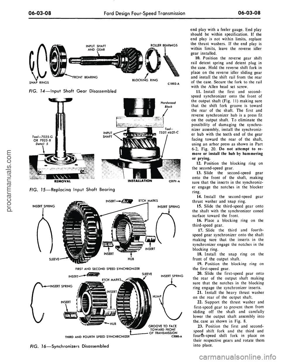
INPUT SHAFT BEARING
1.
Remove the snap ring that se-
cures the bearing to the shaft (Fig.
14).
2.
Press the input shaft gear out of
the bearing as shown in Fig. 15.
3.
Press a new bearing onto the
input shaft with the tool shown in Fig.
15.
4.
Secure the bearing with a snap
ring.
SYNCHRONIZERS
1.
Push the synchronizer hub from
each synchronizer sleeve (Fig. 16).
2.
Separate the inserts and insert
springs from the hubs. Do not mix the
parts of the first and second-speed
C1529-C
synchronizer with the third and
fourth-speed synchronizer.
3.
Position the hub in the sleeve,
making sure that the alignment marks
are properly indexed.
4.
Place the three inserts into place
on the hub. Install the insert springs
making sure that the irregular surface
(hump) is seated in one of the inserts.
Do not stagger the springs.
COUNTERSHAFT GEAR
BEARINGS
1.
Remove the dummy
sKo.ft,
two
bearing retainer washers, and the 21
roller bearings (Fig. 17) from each
end of the countershaft gear.
2.
Coat the bore in each end of the
countershaft gear with grease.
3.
Hold the dummy shaft in the
gear and install the 21 roller bearingsprocarmanuals.com
Page 286 of 413

06-03-07
Ford Design Four-Speed Transmission
06 03-07
and a retainer washer in each end of
the gear.
REVERSE IDLER GEAR
BEARINGS
1.
Slip the reverse idler sliding gear
off the reverse idler gear (Fig. 18).
2.
Remove the dummy shaft, two
bearing retainer washers and the 44
roller bearings from the reverse idler
gear.
3.
Coat the bore in each end of the
reverse idler gear with grease.
4.
Hold the dummy shaft in the
gear and install the 22 roller bearings
and the retainer washer in each end of
the gear.
5. Install the reverse idler sliding
gear on the reverse idler gear making
sure that the shift fork groove is
toward the front (Fig. 18).
INPUT SHAFT SEAL
1.
Remove the seal from the input
shaft bearing retainer as shown in Fig.
19.
2.
Coat the sealing surface with lu-
bricant.
3.
Install the seal as shown in Fig.
20
ASSEMBLY
1.
Coat the countershaft gear thrust
surfaces in the case with a thin film of
lubricant and position a thrust washer
(Fig. 17) at each end of the case.
2.
Position the countershaft gear,
dummy shaft, and roller bearings in
the case.
3.
Place the case in a vertical posi-
tion.
Align the gear bore and the
thrust washers with the bores in the
case and install the countershaft.
4.
Place the case in a horizontal
position and check the countershaft
gear end play with a feeler gauge. The
end play should be 0.004-0.0018 with-
in specification. If not within these
limits,
replace the thrust washers.
5. After establishing the correct end
play, install the dummy shaft in the
countershaft gear and allow the gear
to remain at the bottom of the case.
6. Coat the reverse idler gear thrust
surfaces in the case with a thin film of
lubricant and position the two thrust
washers (Fig. 18) in place.
7. Position the reverse idler gear,
sliding gear, dummy shaft and the
roller bearings in place making sure
that the shift fork groove in the slid-
ing gear is toward the front of the
case.
8. Align the gear bore and thrust
washers with the case bores and install
the reverse idler shaft.
9. Measure the reverse idler gear
REVERSE GEAR CAM AND SHAFT-7C124
•
FIRST AND SECOND SPEED CAM AND SHAFT-7C124
O-RING-7288
THIRD AND FOURTH SPEED
CAMANDSHAFT-7C124
FIRST AND SECOND SPEED SHIFT LEiVER-7290
44727-S
34807-S
33800-S
THIRD AND FOURTH SPEED SHIFT LEVER-7285
44727-S'
34807-S 33800-S C1767-A
FIG. 12—Cam and Shafts and Shift Levers Disassembled
SELECTOR LEVER
SHAFT
INNER SUPPORT
BRACKET
OUTER SUPPORT
BRACKET
REVERSE SELECTOR LEVER
FIRST-SECOND
SELECTOR LEVER
C 2054.A
FIG. 13—Gear Shift Control Assemblyprocarmanuals.com
Page 287 of 413

06-03-08
Ford Design Four-Speed Transmission
06-03-08
ROLLER BEARINGS
SNAP RINGS
FIG. 14—Input Shaft Gear Disassembled
C1802-
A
Hardwood
Block
Tool-7025-G
OR
7025-B
Detail
5
REMOVAL
FIG. 15—Replacing Input Shaft Bearing
INSERT SPRING
INSTALLATION
ETCH MARKS
C2079-A
INSERT SPRING
SLEEVE
HUB
FIRST AND SECOND SPEED SYNCHRONIZER
INSERT
INSERT SPRING
INSERT
SLEEVE
INSERT SPRING
HUMP
THIRD
AND
FOURTH SPEED SYNCHRONIZER
FIG. 16—Synchronizers Disassembled
GROOVE
TO
FACE
TOWARD FRONT
OF TRANSMISSION
C2080.A
end play with
a
feeler gauge. End play
should
be
within specification.
If the
end play
is not
within limits, replace
the thrust washers.
If the end
play
is
within limits, leave
the
reverse idler
gear installed.
10.
Position
the
reverse gear shift
rail detent spring
and
detent plug
in
the case. Hold
the
reverse shift fork
in
place
on the
reverse idler sliding gear
and install
the
shift rail from
the
rear
of
the
case. Secure
the
fork
to the
rail
with
the
Allen head
set
screw.
11.
Install
the
first
and
second-
speed synchronizer onto
the
front
of
the output shaft (Fig.
11)
making sure
that
the
shift fork groove
is
toward
the rear
of the
shaft.
The
first
and
reverse synchronizer
hub is a
press
fit
on
the
output shaft.
To
eliminate
the
possibility
of
damaging
the
synchro-
nizer assembly, install
the
synchroniz-
er
hub
with
the
teeth
end of the
gear
facing toward
the
rear
of the
shaft,
using
an
arbor press
as
shown
in
Part
6-2,
Fig. 20. Do not
attempt
to re-
move
or
install
the
hub
by
hammering
or prying.
12.
Position
the
blocking ring
on
the second-speed gear.
13.
Slide
the
second-speed gear
onto
the
front
of the
shaft, making
sure that
the
inserts
in the
synchroniz-
er engage
the
notches
in the
blocker
ring.
14.
Install
the
second-speed gear
thrust washer
and
snap ring.
15.
Slide
the
third-speed gear onto
the shaft with
the
synchronizer coned
surface toward
the
front.
16.
Place
a
blocking ring
on the
third-speed gear.
17.
Slide
the
third
and
fourth-
speed gear synchronizer onto
the
shaft
making sure that
the
inserts
in the
synchronizer engage
the
notches
in the
blocking ring.
18.
Install
the
snap ring
on the
front
of the
output shaft.
19.
Position
the
blocking ring
on
the first-speed gear.
20.
Slide
the
first-speed gear onto
the rear
of the
output shaft making
sure that
the
notches
in the
blocking
ring engage
the
synchronizer inserts.
21.
Install
the
heavy thrust washer
on
the
rear
of the
output shaft.
22.
Support
the
thrust washer
and
first-speed gear
to
prevent them from
sliding
off the
shaft
and
carefully
lower
the
output shaft assembly into
the.
case
as
shown
in Fig. 8.
23.
Position
the
first
and
second-
speed shift fork
and the
third
and
fourfh-speed shift fork
in
place
on
their respective gears
and
rotate them
into place.procarmanuals.com
Page 288 of 413

06-03-09
Ford Design Four-Speed Transmission
06-03-09
24.
Place a detent plug (Fig. 5) in
the detent bore. Place the reverse shift
rail into neutral position.
25.
Coat the third and fourth-
speed shift rail interlock pin with
grease and position it in the shift rail.
26.
Align the third and fourth-
speed shift fork with the shift rail
bores and slide the shift rail into place
making sure that the three detents are
facing toward the outside of the case.
Place the front synchronizer into
third-speed position and install the set
screw in the third and fourth-speed
shift fork. Move the synchronizer to
the neutral position. Install the third
and fourth-speed shift rail detent plug,
spring and bolt in the left side of the
transmission case (Fig. 5). Place the
interlock plug (tapered ends) in the
detent case.
27.
Align the first and second-
speed shift fork with the case bores
and slide the shift rail into place. Se-
cure the fork with the set screw.
28.
Coat the input gear bore with a
thin film of grease, then install the 15
roller bearings in the bore. A thick
film of grease could plug the lubricant
holes and restrict lubrication of the
bearings.
29.
Position the front blocking ring
in the third and fourth-speed synchro-
nizer.
Place the input shaft gear in the
transmission case making sure that
the output shaft pilot enters the roller
bearings in the input gear.
30.
Place a new gasket on the input
shaft bearing retainer. Dip the attach-
ing bolts in sealer and install and
tighten them to specifications.
31.
Install the output shaft bearing
as shown in Fig. 21. Install the snap
ring to retain the bearing.
32.
On some transmissions, position
the speedometer gear iometer drive
gear retaining clip on the output shaft
with the lower tang in the retaining
hole.
Align the groove in the gear with
the clip and slide the gear forward
until the upper tang on the clip locks
the gear (Fig. 4).
33.
Place the transmission in a ver-
tical position as shown in Fig. 22.
Align the countershaft gear bore and
thrust washers with the bore in the
case.
Install the countershaft.
34.
Use a new gasket and secure
the extension housing to the case with
the attaching screws. Use a sealer on
the extension housing attaching
screws. Torque the screws to specifica-
tions.
35.
Install the filler plug and drain
plug (if so equipped) in the case if
they were removed. Make sure that
COUNTIERSHAFT
7111
RETAINER WASHER
378559 • S
THRUST WASHER -7119
THRUST
WASHER
7119
ROLLER BEARINGS- 7121(21)
COUNTERSHAFT GEAR - 7113
ROLLER BEARINGS'7121(21)
RETAINER
WASHER
378559 • S
FIG. 17—Countershaft Gear Disassembled
C2081-A
REVERSE IDLER
GEAR SHAFT
7140
ROLLER BEARINGS
7D271 22)
THRUST WASHER
7149
RETAINER
WASHER
351529 - S
REVERSE IDLER GEAR -7142
'REVERSE SLIDING GEAR • 7D223
•THRUST WASHER • 7149
FIG. 78—Reverse Idler Gear Disassembled
C2082-A
the magnetic plug (if so equipped) is
installed in the bottom of the case.
36.
Pour the specified lubricant
over the entire gear train while rotat-
ing the input shaft.
37.
Place each shift fork in all posi-
tions to make sure that they operate
properly.
38.
Install the remaining detent
plug in the case. Install the long
spring (which is retained by the case)
to secure the detent plug.
39.
Use a new cover gasket and in-
stall the cover. Coat the cover attach-
ing screws with sealer and install and
tighten them to specifications.
40.
Coat the third- and fourth-
speed shift rail plug bore with a sealer
and install a new expansion plug.
41.
If the extension housing bush-
ing and seal are to be replaced, refer
to Section 1.procarmanuals.com