1969 FORD MUSTANG motor
[x] Cancel search: motorPage 3 of 413

FOREWORD
The five volumes of
this
shop manual provide the Service Technician
with complete information for the proper servicing of all the 1969 line
of Ford Passenger Cars.
The information is grouped according to the type of work being per-
formed,
such as frequently performed adjustments and repairs, in-
vehicle adjustments, major repair, etc. Specifications, maintenance
information and recommended special tools are
included.
The descriptions and specifications in this manual were in effect at the
time this manual was approved for printing. Ford Motor Company
reserves the right to discontinue models at any time, or change specifi-
cations
or design, without notice and without incurring obligation.
SERVICE PUBLICATIONSprocarmanuals.com
Page 14 of 413

02-01-03
Brakes
02-01-03
vacuum system is operating, the pedal
will tend to fall away under foot pres-
sure and less pressure will be required
to hold the pedal in the applied posi-
tion. If no action is felt, the vacuum
booster system is not functioning.
If the brake pedal movement feels
spongy, bleed the hydraulic system to
remove air from the system. Refer to
Hydraulic System Bleeding, Part 1,
Section 2.
VACUUM TESTS—VACUUM
RELEASE PARKING BRAKES
Visually check the operation of the
brake linkage as the brake pedal is
depressed. Then, check the operation
of the brake linkage when the manual
release lever is activiated. These
checks should indicate whether the
manual parking brake control linkage
is operating properly or requires re-
pair or adjustment due to inability of
the parking brake to hold against
moderate vehicle movement. Perform
tests of the parking brake system and
controls after making certain the link-
age and manual controls operate
properly.
When testing a parking brake vacu-
um release system, a minimum of 10
inches of vacuum (Hg.) should be
available at all points where vacuum is
applied. This can be checked with a
Rotunda Fuel Pump Tester Gauge
(ARE345) and two Distributor Tester
hose adapters (Marked Q) connected
together with a coupling. This allows
the Fuel Pump Tester Gauge hose to
be adapted to any other vacuum hose
or rubber connector in the vacuum
systems.
Failure to maintain 10 inches of
vacuum (Hg.) during vacuum system
tests could be caused by a loose hose
connection, resulting in a vacuum
leak. When checking for vacuum be-
tween two points, trace the hose along
the entire routing to be sure it is not
crossed with another hose and con-
nected to the wrong connection.
All of the vacuum parking brake
control checks are to be performed
with the engine running at idle speed.
Leaks in the parking brake hoses or
a disconnected or improperly con-
nected hose can usually be found by
listening for a hissing sound along the
hose routings. Under no circumstances
should air pressure be applied to the
vacuum system as the actuator dia-
phragm in the parking brake vacuum
motor may be damaged.
1.
Start the engine and run it at
idle speed. With the transmission shift
control in neutral, depress the parking
brake pedal to apply the parking
brake. Move the transmission shift
control to D range and observe the
parking brake pedal to see that the
pedal moves upward and the parking
brake releases. If the parking brake
releases, the parking brake vacuum
control is working properly.
2.
If the parking brake does not re-
lease, test for vacuum at the steering
column neutral switch port in the
junction block, vacuum lines and the
parking brake release vacuum motor.
Use the Rotunda Vacuum and Fuel
Pump Tester 345. This can be accom-
plished by removing the hose from
each component and attaching it to
the vacuum gauge. Connect two dis-
tributor tester vacuum hose adapters
together with a coupling as a connec-
tor to attach the gauge. A minimum
of ten inches of vacuum is required to
actuate the parking brake vacuum
motor. Do not remove any of the vac-
uum hoses from the junction block
unless the junction block is being re-
placed, as the plastic nipples are thin
and very brittle and damage may re-
sult. If a minimum reading is not
present when checking each of the
aforementioned components, they
must be replaced.
ROAD TEST
A road test should be conducted
only when the operator is sure the
brakes will stop the vehicle.
If the road test reveals one or more
problem conditions, correct all mal-
functions of the vacuum system, brake
booster and hydraulic system prior to
removing brake drums, brake calipers,
brake shoes and linings or backing
plates.
ANTI-SKID CONTROL
SYSTEM TESTS
No adjustments or repairs are to be
performed on the skid control system.
Damaged or worn parts are to be re-
placed.
Refer to Ford Car and Truck Diag-
nosis Manual for Testing procedures.
COMMON ADJUSTMENTS AND REPAIRS
PARKING BRAKE LINKAGE
ADJUSTMENT
FORD, MERCURY, METEOR,
FAIRLANE, MONTEGO,
FALCON, MUSTANG
AND COUGAR
Check the parking brake cables
when the brakes are fully released. If1
the cables are loose, adjust them as
follows:
1.
Fully release the parking brake
pedal by pulling the release lever.
2.
Depress the parking brake pedal
until it is engaged in the first notch of
the control. On a vacuum release
brake, the first notch will be approxi-
mately two inches of pedal travel.
3.
Raise the vehicle. With the
transmission in neutral, turn the ad-
justing nut forward against the equal-
izer (Figs. 3 and 4) until there is 100
L.H. REAR WHEEL CABLE -2A809> 2A791 (2 REQUIRED)
EQUALIZER-TO-ACTUATOR CABLE-2A815
R.H. REAR WHEEL CABLE-2A635
ADJUSTING NUT-2A812
H 1537-C
FIG. 3—Parking Brake Adjustment—Ford, Mercury, Meteor,
Thunderbird and Continental Mark IIIprocarmanuals.com
Page 42 of 413

02-02-23
Brake System
02-02-23
BOOSTER ASSEMBLY- 2005
NUT-34444-S7
HOSE 2A047
MASTER CYLINDER
IDENTIFICATION
BRAKE TUBE-2263
BRAKE TUBE -2264
PRESSURE DIFFERENTIAL
VALVE ASSEMBLY-2B257
BRAKE TUBE-2B255
H 15S3-B
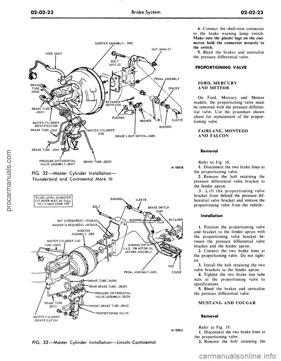
FIG. 32—Master Cylinder Installation-
Thunderbird and Continental Mark III
FLUID LEVEL IN MASTER
CYLINDER MUST 3E FULL
TO 1/4 INCH FROM TOP
BUSH
SLEEVE
BOLT
BRAKE SWITCH
13480
NUT (4 REQUIRED) -55768-S2
WASHER"(4 REQUIRED) -44726-S8
BOOSTER
ASSEMBLY 2005
MASTER CYLINDER 2WO
HOSE-2A047
BUSHING DIP IN
S.A.E. 10W MOTOR OIL
BEFORE ASSEMBLY
PEDAL ASSEM6LY-2455
COVER
BRAKE TUBE-2A040
REAR BRAKE TUBE -2B329
PRESSURE DIFFERENTIAL
VALVE ASSEMBLY-2B328
FRONT BRAKE TUBE-2B162
PROPORTIONING VALVE
MASTER CYLINDER
IDENTIFICATION
H 1530-C
FIG. 33—Master Cylinder Installation—Lincoln Continental
4.
Connect the shell-wire connector
to the brake warning lamp switch.
Make sure the plastic lugs on the con-
nector hold the connector securely to
the switch.
5. Bleed the brakes and centralize
the pressure differential valve.
PROPORTIONING VALVE
FORD, MERCURY
AND METEOR
On Ford, Mercury and Meteor
models, the proportioning valve must
be removed with the pressure differen-
tial valve. Use the procedure shown
above for replacement of the propor-
tioning valve.
FAIRLANE, MONTEGO
AND FALCON
Removal
Refer to Fig. 18.
1.
Disconnect the two brake lines at
the proportioning valve.
2.
Remove the bolt retaining the
pressure differential valve bracket to
the fender apron.
3.
Lift the proportioning valve
bracket from behind the pressure dif-
ferential valve bracket and remove the
proportioning valve from the vehicle.
Installation
1.
Position the proportioning valve
and bracket to the fender apron with
the proportioning valve bracket be-
tween the pressure differential valve
bracket and the fender apron.
2.
Connect the two brake lines at
the proportioning valve. Do not tight-
en.
3.
Install the bolt retaining the two
valve brackets to the fender apron.
4.
Tighten the two brake line tube
nuts at the proportioning valve to
specifications.
5.
Bleed the brakes and centralize
the pressure differential valve.
MUSTANG AND COUGAR
Removal
Refer to Fig. 19.
1.
Disconnect the two brake lines at
the proportioning valve.
2.
Remove the bolt retaining theprocarmanuals.com
Page 49 of 413

02-02-30
Brake System
02-02-30
7.
Disconnect the wire lead at the
parking brake warning light switch
and remove the control assembly.
Installation
1.
Connect the wire lead to the
parking brake warning light switch.
2.
Position the control assembly to
the cowl inner side panel and install
the three attaching screws.
3.
Connect the ball-end of the park-
ing brake front cable assembly to the
control assembly, and install the hair-
pin retainer.
4.
Position the cable ball in the
notch in the brake clevis.
5.
Position the left air vent assem-
bly to the dash and instrument panels.
Install the four bolts and one nut re-
taining the air vent to the panels.
6. Check the operation of the park-
ing brake. Adjust the parking brake.
MUSTANG AND COUGAR
Removal
Refer to Fig. 36.
1.
Make sure the parking brake is
completely released,
2.
Remove all tension from the rear
cables by backing off the jam nut and
adjusting nut from the equalizer.
3.
Disconnect the wire lead at the
parking brake warning light switch (if
so equipped).
4.
Remove the parking brake front
cable ball retaining clip from the clev-
is.
5.
Remove the parking brake warn-
ing light switch and attaching screw (if
so equipped).
6. Disconnect the cable ball from
the notch in the brake clevis.
7.
Remove the three screws that at-
tach the control assembly to the left
cowl inner side panel.
8. Pull the control away from the
cowl, panel. Remove the hair-pin re-
tainer securing the front cable assem-
bly to the control assembly. Remove
the control assembly
Installation
1.
Connect the ball-end of the park-
ing brake front cable assembly to the
control assembly, and install the hair-
pin retainer.
2.
Position the control assembly to
the cowl inner side panel and install
the three attaching screws.
3.
Position the parking brake warn-
ing light switch and install the attach-
ing screw. Connect the parking brake
warning light switch wire lead (if vehi-
cle is so equipped).
4.
Position the cable ball in the
notch in the brake clevis.
5.
Check the operation of the park
ing brake. Adjust the parking brake.
THUNDERBIRD AND
CONTINENTAL MARK III
Removal
Refer to Fig. 37.
1.
Remove the two nuts retaining
the control to the dash panel.
2.
Remove two screws from the left
scuff plate.
3.
Remove one screw retaining the
left cowl trim panel and remove the
panel.
4.
Remove the two screws retaining
the left air duct and remove the air
duct.
5.
Remove the two screws retaining
the dimmer switch and position the
switch out of the way.
6. Remove the clip retaining the
cable assembly to the control.
7.
Disconnect the cable ball from
the control clevis.
8. Disconnect the vacuum hose at
the brake release.
9. Remove the bolt retaining the
control to the cowl side bracket and
remove the control.
Installation
1.
Position the parking brake con-
trol in the vehicle.
2.
Install the cable assembly in the
control and connect the cable ball to
the control clevis.
3.
Install the clip retaining the
cable to the control.
4.
Install the bolt retaining the con-
trol to the cowl side bracket.
5.
Connect the vacuum hose to the
parking brake release vacuum motor.
6. Position the dimmer switch and
install the retaining screws.
7.
Position the air duct and install
the retaining screws.
8. Position the cowl trim panel and
install the retaining screw.
9. Install the two scuff plate screws.
10.
Install the two nuts retaining
the control to the dash panel.
11.
Adjust the parking brakf
LINCOLN CONTINENTAL
Removal
Refer to Fig. 38.
1.
Raise the vehicle on a hoist.
2.
Loosen the parking brake cable
adjusting nut, remove the return
spring and remove the cable ball end
from the equalizer.
3.
Lower the vehicle.
4.
Disconnect the battery.
5.
Disconnect the wire harness con-
nector and two vacuum hoses at the
Automatic Temperature Control box.
6. Working inside the vehicle, re-
move the windshield wiper control
knob and bezel from the lower control
panel.
7.
Remove the screws retaining the
lower control panel. Lower the control
panel and disconnect wire harnesses
and vacuum hoses. Position the con-
trol panel aside.
8. Remove the screw retaining the
plastic wire cover and place 'the cover
aside.
9. Disconnect three vacuum hoses
and the wiring harness at the Auto-
matic Temperature Control box.
10.
Remove the two screws retain-
ing the Automatic Temperature Con-
trol box to the dash panel and remove
the box for clearance.
11.
Disconnect the ball end of the
cable from the control clevis.
12.
Remove the four bolts retaining
the control to the dash panel and
lower instrument panel flange.
13.
Disconnect the vacuum release
hose from the control and remove the
control assembly from the vehicle.
Installation
1.
Position the control assembly to
the dash panel and instrument panel
flange and install the four retaining
screws.
2.
Connect the vacuum release hose
to the control assembly.
3.
Connect the cable ball to the
control clevis.
4.
Position the Automatic Temper-
ature Control box to the dash panel
and install the retaining screws.
5.
Connect the wiring harness and
vacuum hoses to the Automatic Tem-
perature Control box.
6. Position the plastic wire covei
and install the retaining screw.
7.
Connect the wire harnesses and
vacuum lines to the lower control
panel and position the panel to the inprocarmanuals.com
Page 114 of 413

03-05-01
Steering Columns And Linkage
03-05-01
PART 3-5 Steering
Columns
and Linkage
COMPONENT INDEX
ADJUSTING SLEEVE (LINKAGE)
Removal and Installation
CENTER LINK (LINKAGE)
Removal and Installation
LOCKING LEVER (TILT-AWAY COLUMN)
Removal and Installation
PITMAN ARM (LINKAGE)
Removal and Installation
SPINDLE CONNECTING ROD ASSEMBLY
(Inner and Outer Ends)
Removal and Installation
STATIONARY STEERING COLUMNS
Description
STEERING COLUMN
Alignment
Removal and Installation
STEERING COLUMN SHIFT TUBE
Removal and Installation
STEERING COLUMN UPPER BEARING
Removal and Installation
STEERING IDLER ARM AND BRACKET
ASSEMBLY
Removal and Installation
STEERING WHEEL
Removal and Installation
Spoke Position Adjustment
TILT-AWAY STEERING COLUMN
Description
TILT STEERING COLUMN
Description
TILT WHEEL STEERING COLUMN
STEERING SHAFT
Removal and Installation
VACUUM MOTOR (TILT-AWAY COLUMN)
Removal and Installation
VACUUM RELEASE VALVE (TILT-AWAY
COLUMN)
Removal and Installation
MODEL APPLICATION
All
Models
05-19
05-20
05-20
05-01
05-14
05-02
05-20
05-02
05-02
Ford
N/A
05-19
N/A
05-08
N/A
05-01
05-16
N/A
N/A
Mercury
N/A
05-19
N/A
05-08
N/A
05-01
05-16
N/A
N/A
Meteor
N/A
05-19
N/A
05-08
N/A
05-01
05-16
N/A
N/A
Cougar
05-06
05-19
N/A
05-10
05-02
N/A
N/A
05-05
05-05
Fairlane
N/A
05-19
N/A
05-09
N/A
N/A
N/A
N/A
N/A
Falcon
N/A
05-19
N/A
05-09
N/A
N/A
N/A
N/A
N/A
Montego
N/A
05-19
N/A
05-09
N/A
N/A
N/A
N/A
N/A
Mustang
05-06
05-19
N/A
05-10
05-02
N/A
N/A
05-05
05-05
Lincoln-
Continental
N/A
05-19
05-06
05-11
N/A
05-01
05-16
N/A
N/A
Thunderbird
05-06
05-19
05-07
05-14
05-02
N/A
N/A
05-05
05-05
Continental-
Mark
III
N/A
05-19
05-06
05-11
N/A
05-01
05-16
N/A
N/A
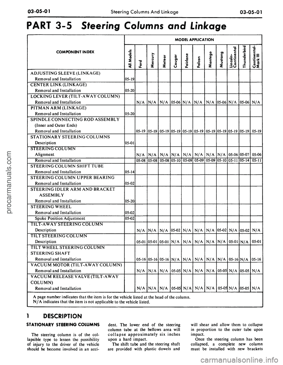
A page number indicates that the item is for the vehicle listed at the head of the column.
N/A indicates that the item is not applicable to the vehicle listed.
1 DESCRIPTION
STATIONARY STEERING COLUMNS
The steering column is of the col-
lapsible type to lessen the possibility
of injury to the driver of the vehicle
should he become involved in an acci-
dent. The lower end of the steering
column tube at the bellows area will
collapse approximately six inches
upon a hard impact.
The shift tube and the steering shaft
are provided with plastic dowels and
will shear and allow them to collapse
in proportion to the outer tube upon
impact.
Once the steering column has been
collapsed, a complete new column
must be installed with new brackets
procarmanuals.com
Page 118 of 413

03-05-05
Steering Columns And Linkage
03-05-05
TILT-AWAY STEERING
COLUMN REPAIRS
VACUUM RELEASE VALVE-
COUGAR AND MUSTANG
Removal
1.
Working from the underside of
the instrument panel disconnect the
hose from the valve.
2.
Disconnect the wire from the
connector on the valve and the con-
nector from the relay.
3.
Remove the bracket-
to-instrument panel attaching bolt and
let the bracket swing down.
4.
Remove the two screws that se-
cure the valve to the mounting bracket
and remove the valve.
Installation
1.
Secure the valve to the mounting
bracket with the two attaching screws.
2.
Position the bracket to the in-
strument panel and install the attach-
ing bolt.
3.
Connect the wire to the terminal
on the valve.
4.
Connect the hose from the vacu-
um motor to the horizontal connector
on the valve and the hose from the
reservoir to the vertical connector.
VACUUM RELEASE VALVE—
THUNDERBIRD
Removal
1.
Remove the lower finish panel.
2.
Disconnect the vacuum hose
from the vacuum release valve.
3.
Disconnect the vacuum release
valve electrical leads at the connector.
4.
Loosen the two attaching screws
holding the bracket to the dash. Lift
up the bracket to clear the screws and
swing it down below the panel.
5.
Remove the screws attaching the
valve to the panel and remove the
valve.
Installation
1.
Position the vacuum release
valve on the bracket.
2.
Install the two attaching screws
and swing the bracket up and over the
screws. Tighten the screws.
3.
Connect the electrical leads to
the wiring harness.
4.
Connect the hose from the vacu-
um dash panel junction block to the
connector on the vacuum release valve
that points downward and forward.
Connect the hose from the vacuum
motor to the other connector on the
release valve.
5.
Install the lower finish panel.
VACUUM MOTOR-
COUGAR AND MUSTANG
Removal
1.
Working from the underside of
the instrument panel, disconnect the
hose to the valve and the wires to the
relay and valve.
2.
Remove the bracket-
to-instrument panel attaching bolt and
swing the bracket downward.
3.
Remove the clevis pin that se-
cures the cable to the vacuum motor
rod.
4.
Disconnect the starter safety
switch wire at the connector.
5.
Remove the two motor-
to-bracket attaching screws and re-
move the motor, disconnecting the
hose to the solenoid.
Installation
1.
Position the motor on the
mounting bracket and the attaching
screws.
2.
Connect the control cable to the
vacuum motor rod with the clevis pin.
3.
Position the bracket to the in-
strument panel and install the attach-
ing bolt. Make all electrical and vacu-
um connections.
4.
Readjust the cable bracket to as-
sure full engagement of the locking
pawl when in driving position.
5.
Connect the hose to the vacuum
motor.
VACUUM MOTOR—
THUNDERBIRD
Removal
1.
Remove the lower finish panel.
2.
Disconnect the vacuum hose
from the solenoid valve. Disconnect
the electrical lead.
3.
Loosen the screws that attach
the bracket to the dash and lift the
bracket up; then, swing it down.
4.
Remove the clevis pin holding
the motor to the cable.
5.
Remove the two attaching
screws, then lift the motor from the
bracket.
C-CLAMP
PIVOT PIN
G 1462-A
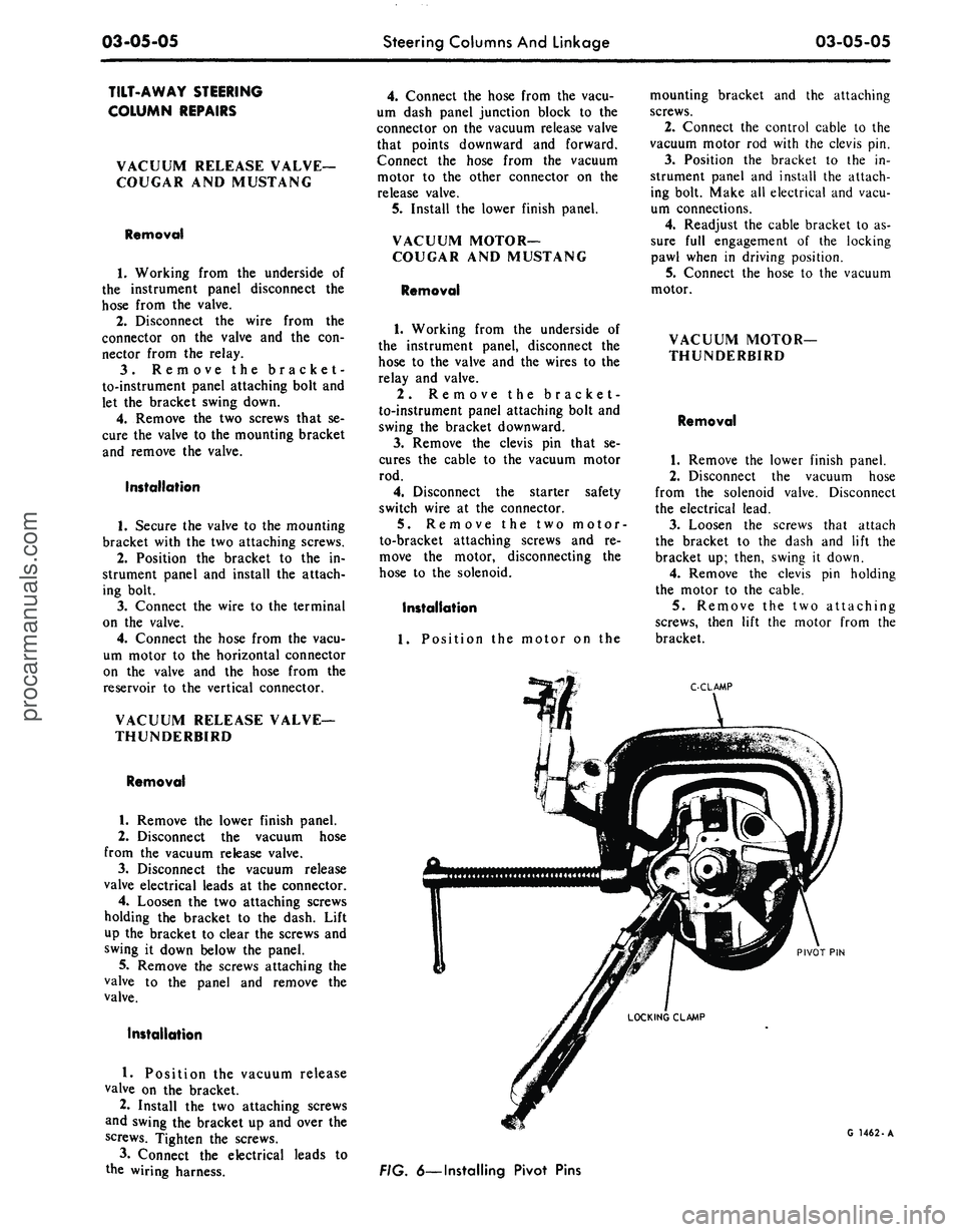
FIG. 6—Installing Pivot Pinsprocarmanuals.com
Page 119 of 413

03-05-06
Steering Columns And Linkage
03-05-06
Installation.
1.
Position the vacuum motor on
the bracket. Tighten the two attaching
screws.
2.
Connect the cable to the motor
with the clevis pin. Adjust the cable
bracket so the motor rod is fully ex-
tended, but not tight.
3.
Slide the vacuum motor as re-
quired to align the locking pawl rod
and vacuum motor. Retighten the two
vacuum motor attaching screws.
4.
Connect the vacuum hose to the
vacuum motor.
5.
Install the lower finish panel.
LOCKING LEVER
REPLACEMENT
Removal
1.
Remove the upper flange and
bearings from the column.
2.
Insert a 3
1/8-inch
bolt between
the lower ends of the locking levers
(Fig. 7) to relieve the tension from the
column release lever.
3.
Place the flange in a vise as
shown (Fig. 7) and remove the two re-
tainers with a screwdriver.
4.
Lift the column release lever
from the flange.
5.
Drive the locking lever retaining
pins from the flange with a small
drift.
6. Release the vise slowly to pre-
vent the levers from flying out.
LEVER RETAINING
PINS
3-1/8'
7.
Remove the levers, spring caps
and springs from the flange.
Installation
1.
Make sure that the rubber insu-
lators are in place in the upper flange.
2.
Position the springs, spring caps
and locking levers in the upper flange.
3.
Place the assembly in a vise and
compress the springs. Install new lever
retaining pins in the upper flange. The
pins should protrude from the sides of
the flange by .03 to .09 inch.
4.
Install a 3
1/8-inch
bolt between
the lower ends of the locking levers as
shown in Fig. 7.
5.
Make sure that the column re-
lease lever stop and spring is in place
in the upper flange, then position the
column release lever on the flange. In-
stall the two retainers.
6. Remove the 3
1/8-inch
bolt from
between the levers.
7.
Install the upper flange and
bearings in the steering column.
STEERING COLUMN
ALIGNMENT
THUNDERBIRD AND
CONTINENTAL MARK III
A condition of high shift or steering
efforts may be experienced caused by
improper alignment of the energy ab-
sorbing steering column. The fol-
lowing procedures outline the steps
necessary to correctly re-align either
fixed or tilt columns.
It is recommended that before at-
tempting realignment, the toe plate
(column retainer) to dash panel fas-
tener holes be inspected for a binding
or misaligned condition.
If the conditions described above
could be attributed to this area, file or
ream the dash panel holes for greater
clearance.
The column alignment procedures:
1.
Loosen the nuts retaining the toe
plate (column retainer) to the dash
panel (B in Fig. 8).
2.
Loosen to fingertight the bolt
and nut located on the toe plate re-
taining clamp (C in Fig. 8).
3.
Remove trim at instrument panel
to steering column mounting to ex-
pose retaining bolts.
4.
Loosen to fingertight {.he bolts
that support the column and bracket
against the instrument panel (D in
Fig. 8).
5.
Loosen to fingertight the bolts or
nuts which retain the column brackets
to the brake pedal support bracket
(E).
6. Loosen to fingertight the bolt
which controls lateral adjustment of
RETAINER
B
c
D
E
F
TORQUE VALUE
8-12 FT. LB.
3-5 FT. LB.
7.12 FT. LB.
7.12 FT. LB.
28-42 FT. LB.
G1536-A
FIG. 7—Removing or Installing
Locking Levers
FIG. 8—Steering Column Alignment Locations and Torque Specificationsprocarmanuals.com
Page 123 of 413

03-05-10
Steering Columns And Linkage
03-05-10
9. Connect the battery cable to the
negative post.
10.
Check the operation of the
switches.
COUGAR, MUSTANG
Removal
cable
1.
Disconnect the battery
from the negative post.
2.
Disconnect the turn signal switch
wires at the connector.
3.
On tilt-away columns, disconnect
the tilt-control cable from the vacuum
motor and mounting bracket.
4.
Remove the bolt that secures the
flex coupling to the steering gear.
5.
Remove the nuts and bolts that
secure the column retainer and seal at
the toe plate.
6. Remove the nuts that secure the
column lower bracket to the brake
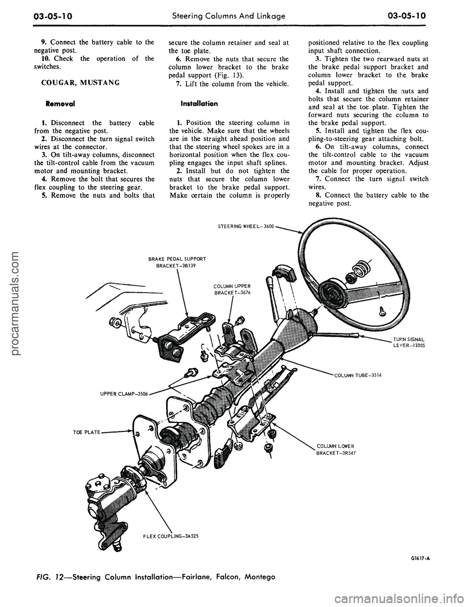
pedal support (Fig. 13).
7.
Lift the column from the vehicle.
Installation
1.
Position the steering column in
the vehicle. Make sure that the wheels
are in the straight ahead position and
that the steering wheel spokes are in a
horizontal position when the flex cou-
pling engages the input shaft splines.
2.
Install but do not tighten the
nuts that secure the column lower
bracket to the brake pedal support.
Make certain the column is properly
positioned relative to the flex coupling
input shaft connection.
3.
Tighten the two rearward nuts at
the brake pedal support bracket and
column lower bracket to the brake
pedal support.
4.
Install and tighten the nuts and
bolts that secure the column retainer
and seal at the toe plate. Tighten the
forward nuts securing the column to
the brake pedal support.
5.
Install and tighten the flex cou-
pling-to-steering gear attaching bolt.
6. On tilt-away columns, connect
the tilt-control cable to the vacuum
motor and mounting bracket. Adjust
the cable for proper operation.
7.
Connect the turn signal switch
wires.
8. Connect the battery cable to the
negative post.
STEERING WHEEL-3600
BRAKE PEDAL SUPPORT
BRACKET-3B139
TOE PLATE
COLUMN LOWER
BRACKET-3R547
FLEXCOUPLING-3A525
G1617-A
FIG. 72—Steering Column Installation—Fairlane, Falcon, Montegoprocarmanuals.com