Page 129 of 413
Page 130 of 413
Page 131 of 413
Page 132 of 413
Page 133 of 413

03-05-20
Steering Columns And Linkage
03-05-20
placed if it becomes worn or damaged
(Figs.
18 through 21). Do not attempt
to straighten the sleeve if damaged.
1.
Remove the spindle connecting
rod end assemblies as described in the
previous sub-section.
2.
Screw the spindle rod end assem-
blies into the new sleeve the same
number of turns as the ends that were
removed. Do not tighten the clamp
bolts at this time.
3.
Position the sleeve and end as-
sembly on the center link and the
spindle arm. Install the attaching nut,
torque it to specification, and install
the cotter pin.
4.
Check and, if necessary, adjust
toe-in (Part 3-1). After toe-in is
checked and adjusted, oil the sleeve
clamp bolts then torque them to speci-
fication. The sleeve clamp must be in-
stalled as shown in Figs. 18 through
21.
CENTER LINK
REPLACEMENT
The center link connecting the Pit-
man arm and the idler arm is non-
adjustable and is provided with ta-
pered holes to accommodate the ball
studs (Figs. 18 through 21). The link
should be replaced when damaged or
when worn at the ball studs. On Lin-
coln Continental models, the link
should be replaced if excessive loose-
ness is noticed in either ball stud sock-
et.
REMOVAL
1.
Raise the vehicle on a hoist and
position safety stands.
2.
Remove the cotter pins and nuts
that attach both inner connecting rod
ends to the center link (Figs. 18
through 21).
3.
Disconnect the inner connecting
rod ends from the center link using
Tool 3290-C (Fig. 22).
4.
Remove the cotter pin and nut
attaching the idler arm to the center
link. Disconnect the idler arm from
the center link using Tool 3290-C for
Lincoln Continental models only.
5.
Remove the cotter pin and nut
attaching the Pitman arm to the cen-
ter link. Disconnect the Pitman arm
from the center link (use Tool 3290-C)
and remove the center link. On ve-
hicles equipped with the non-integral
power steering system, remove the
center link from the control valve as
detailed in Part 3-7.
INSTALLATION
1.
Replace the rubber seals on the
spindle connecting rod ends, if re-
quired.
2.
Position the center link to the
Pitman arm and idler arm and install
the attaching nuts loosely. On all ve-
hicles except Lincoln Continental
models, place the idler arm and the
front wheels in the straight ahead po-
sition to insure keeping the steering
wheel aligned and to prevent bushing
damage after the attaching nuts have
been torqued. On Lincoln Continental
models, insure that the seal is properly
installed on the center link. Torque
the nuts to the low end of the specifi-
cation. Continue to tighten each nut
until the slots in the nut align with the
hole in the stud. Then install a new
cotter pin.
3.
Position the spindle connecting
rod ends to the center link and install
the attaching nuts. Torque the nuts to
the low end of the specification. Con-
tinue to tighten each nut until the
slots in the nut align with the hole in
the stud. Then, install a new cotter
pin.
4.
Remove the safety stands, lower
the vehicle, check and adjust toe-in to
specification (Part 3-1).
STEERING IDLER ARM
AND BRACKET ASSEMBLY
REPLACEMENT
REMOVAL
If the idler arm bushings are worn
the complete idler arm assembly must
be replaced. In Lincoln Continental
models, if the socket at the idler
bracket is excessively loose, replace
the complet assembly.
1.
Remove the cotter pin and nut
attaching the steering center link at
the idler arm (Figs. 18 through 21).
2.
Disconnect the center link from
the idler arm (on Lincoln Continental
models, use Tool 3290-C).
3.
Remove the two bolts that attach
the idler arm and bracket assembly to
the frame.
INSTALLATION
1.
Secure the new idler arm and
bracket assembly to the frame with
the two attaching bolts (nuts and flat
washers as shown in Figs. 18, 19 and
21).
2.
On all vehicles except Lincoln
Continental models, place the idler
arm and the front wheels in the
straight ahead position to insure keep-
ing the steering wheel aligned and to
prevent bushing damage after the at-
taching nut has been torqued. Insert
the center link stud through the hole
in the end of the idler arm and install
the nut and washer.
On Lincoln Continental models, in-
sert the center link stud through the
hole in the end of the idler arm insur-
ing that the seal is properly installed
on the center link.
3.
Torque the idler arm rod nut to
specification and install a new cotter
pin.
PITMAN ARM
REPLACEMENT
REMOVAL
1.
Remove the cotter pin from the
castellated nut that attaches the steer-
ing center link to the Pitman arm.
Remove the castellated nut.
2.
Disconnect the steering center
link from the Pitman arm with tool
3290-C.
3.
Remove the Pitman arm attaching
nut and lock washer.
4.
Position the front wheels in the
straight ahead position. Remove the
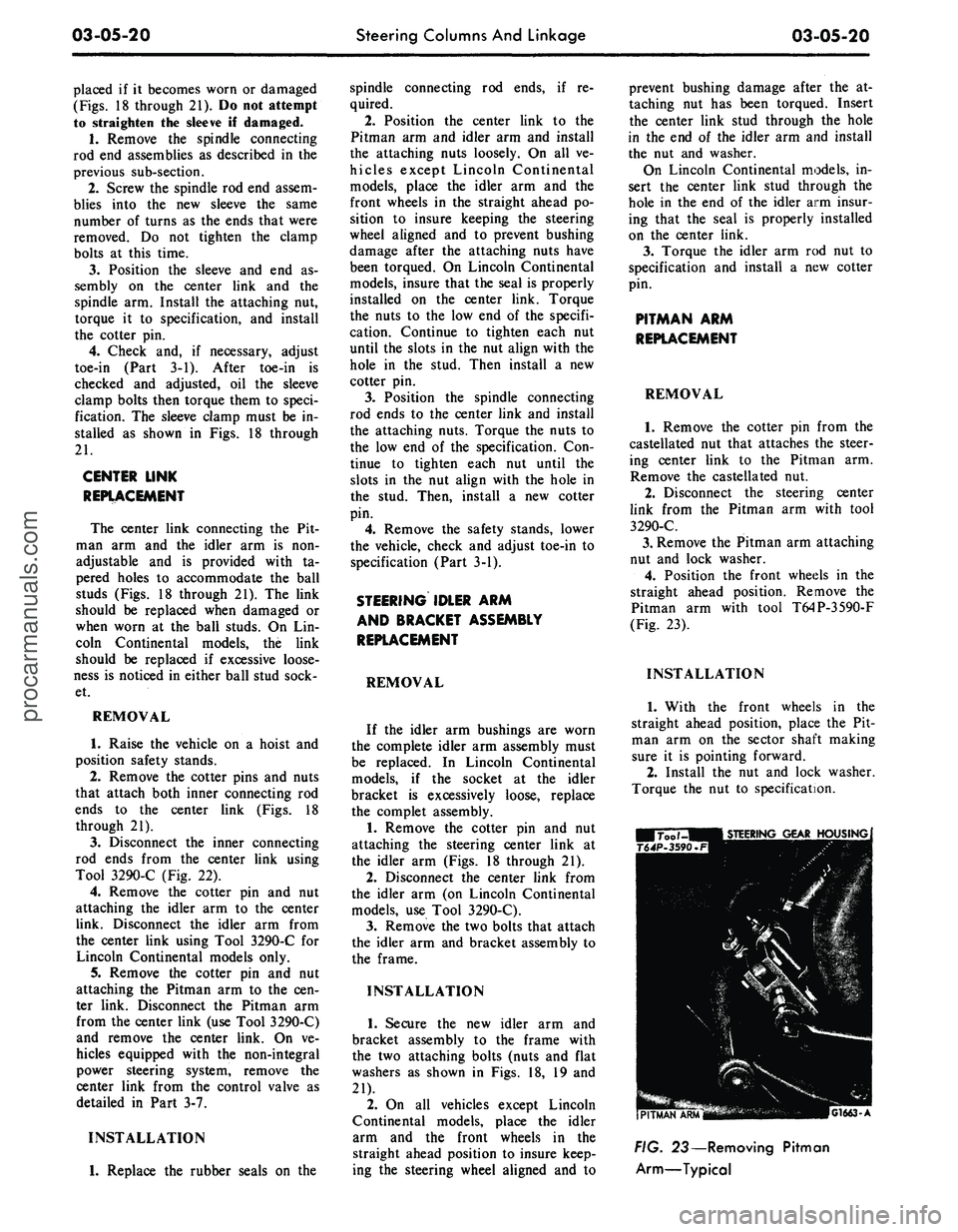
Pitman arm with tool T64P-3590-F
(Fig. 23).
INSTALLATION
1.
With the front wheels in the
straight ahead position, place the Pit-
man arm on the sector shaft making
sure it is pointing forward.
2.
Install the nut and lock washer.
Torque the nut to specification.
G1663-A
FIG. 23— Removing Pitman
Arm—Typicalprocarmanuals.com
Page 134 of 413
03-05-21 Steering Columns And Linkage 03-05-21
3.
Secure
the
steering center link
to
insure that
the
seal
is
properly
in-
tighten
the nut to the
next castellation
the Pitman
arm
with
the
castellated stalled. Torque
the nut to
specification
if
necessary
to
install
the
cotter
pin.
nut.
On
Lincoln Continental models,
and
install
the
cotter
pin.
Alwaysprocarmanuals.com
Page 135 of 413

03-06-01
Manual Steering
03 06-01
PART
3-6
Manual Steering
COMPONENT INDEX
STEERING GEAR
Cleaning
and
Inspection
(See Part 03-01)
Description
Disassembly
and
Overhaul
Removal
and
Installation
STEERING WORM
AND
SECTOR
Adjustment
and
Repair
MODEL APPLICATION
All
Models
Ford
06-01
06-03
06-02
06-02
Mercury
06-01
06-03
06-02
06-02
Meteor
06-01
06-03
06-02
06-02
Cougar
06-01
06-03
06-02
06-02
Fairlane
06-01
06-03
06-02
06-02
Falcon
06-01
06-03
06-02
06-02
Montego
06-01
06-03
06-02
06-02
Mustang
06-01
06-03
06-02
06-02
Lincoln-
Continental
N/A
N/A
N/A
N/A
Thunderbird
N/A
N/A
N/A
N/A
Continental-
Mark
III
N/A
N/A
N/A
N/A
A page number indicates that the item
is for
the vehicle listed
at
the head
of
the column.
N/A indicates that the item
is not
applicable
to
the vehicle listed.
DESCRIPTION
STEERING GEAR
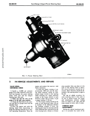
The steering gear
(Fig.
1) is of the
worm
and
recirculating ball type.
The
sector shaft
is
straddle mounted
hav-
INPUT SHAFT
ing
a
bushing located
in the
cover
above
the
gear
and a
roller bearing
in
the housing below
the
gear.
SECTOR SHAFT ADJUSTMENT SCREW
LOCK
NUT
IDENTIFICATION
TAG
SECTOR SHAFT COVER
The worm bearing preload
is con-
trolled
by the
large adjusting
nut
which
is
threaded into
the
housing.
The sector shaft mesh load
is con-
trolled
by an
adjusting screw located
in
the
housing cover.
The steering linkage consists
of the
Pitman
arm,
steering-arm-to-idler
arm
rod, idler
arm and the
spindle
con-
necting rods
(tie
rods).
A steering gear identification
tag is
provided under
one of the
cover
at-
taching bolts
(Fig.
2).
STEERING GEAR
MODEL
SERVICE IDENTIFICATION
CODE NUMBER
FIG.
1—Manual
Steering Gear
SERIAL NUMBER
OR
DATE CODE
G 1625-A
G
1626-A
FIG. 2—Steering Gear Identification
procarmanuals.com
Page 136 of 413

03-06-02
Manual Steering
03-06-02
IN-VEHICLE ADJUSTMENTS AND REPAIRS
STEERING WORM AND
SECTOR
GEAR ADJUSTMENTS
The ball nut assembly and the sec-
tor gear must be adjusted properly to
maintain minimum steering shaft end
play (a factor of preload adjustment)
and minimum backlash between sector
gear and ball nut. There are only two
possible adjustments within the recir-
culating ball-type steering gear, and
these should be made in the following
order to avoid damage or gear failure.
1.
Disconnect the Pitman arm from
the steering Pitman-to-idler arm rod.
2.
Loosen the nut which locks the
sector adjusting screw (Fig. 3), and
turn the adjusting screw counterclock-
wise.
(On models equipped with the
Cobra Jet engine, it may be necessary
to use a suitable holding tool with an
extension and a long screwdriver to
make the gear adjustment).
3.
Measure the worm bearing pre-
load by attaching an in-lb torque
wrench to the steering wheel nut (Fig.
4).
With the steering wheel off center,
read the pull required to rotate the
input shaft approximately 1 1/2 turns
either side of center. If the torque or
preload is not within specification
(Part 3-1), adjust as explained in the
next step.
.•ADJUSTER
LOCK
NUT
SECTOR
SHAFT
ADJUSTING
SCREW
G
1627-A
FIG. 3—Steering Gear
Adjustments—Typical
4.
Loosen the steering shaft bearing
adjuster lock nut, and tighten or back
off the bearing adjuster (Fig. 1) to
bring the preload within the specified
limits.
5.
Tighten the steering shaft bear-
ing adjuster lock nut, and recheck the
preload.
6. Turn the steering wheel slowly to
either stop. Turn gently against the
stop to avoid possible damage to the
ball return guides. Then rotate the
wheel 2-3/4 turns to center the ball
nut.
7.
Turn the sector adjusting screw
clockwise until the specified torque
(Part 3-13) is necessary to rotate the
worm past its center (high spot) (Fig.
1).
8. While holding the sector adjust-
ing screw, tighten the sector adjusting
screw locknut to specification, and re-
check the backlash adjustment.
9. Connect the Pitman arm to the
steering arm-to-idler arm rod.
G-1495-A
FIG. 4—Checking Steering Gear
Preload—Typical
REMOVAL AND INSTALLATION
STEERING GEAR
REMOVAL
1.
Remove the bolt(s) that retains
the flex coupling to the steering shaft.
2.
Remove the nut and lock washer
that secures the Pitman arm to the
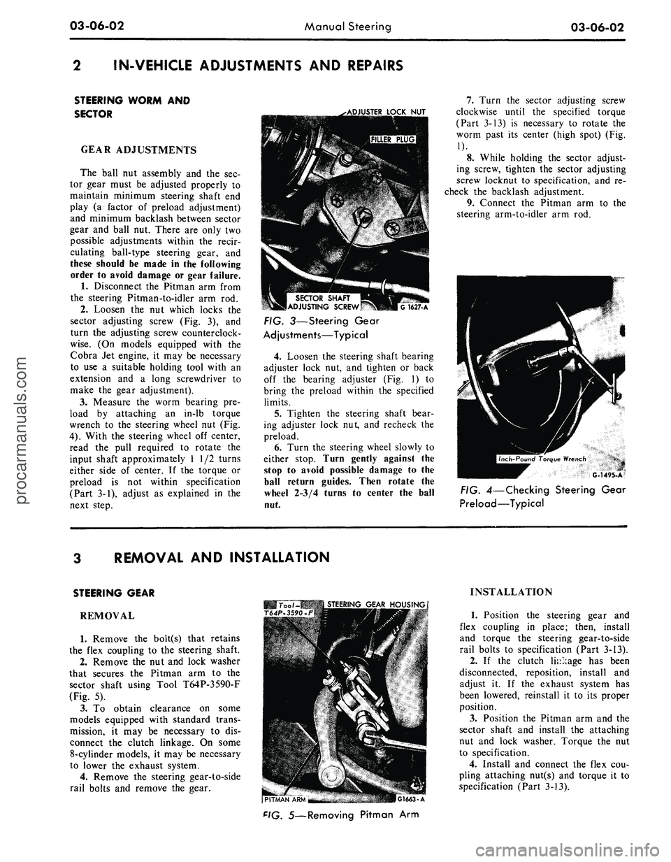
sector shaft using Tool T64P-3590-F
(Fig. 5).
3.
To obtain clearance on some
models equipped with standard trans-
mission, it may be necessary to dis-
connect the clutch linkage. On some
8-cylinder models, it may be necessary
to lower the exhaust system.
4.
Remove the steering gear-to-side
rail bolts and remove the gear.
Too /-MB
STEERING
GEAR
HOUSING
T64P-3590.F
(PITMAN
"APU'^M
-
.-. •
-"
•.:,.17''i.a—
r.iMI.
A
F'G.
5—Removing Pitman Arm
INSTALLATION
1.
Position the steering gear and
flex coupling in place; then, install
and torque the steering gear-to-side
rail bolts to specification (Part 3-13).
2.
If the clutch linkage has been
disconnected, reposition, install and
adjust it. If the exhaust system has
been lowered, reinstall it to its proper
position.
3.
Position the Pitman arm and the
sector shaft and install the attaching
nut and lock washer. Torque the nut
to specification.
4.
Install and connect the flex cou-
pling attaching nut(s) and torque it to
specification (Part 3-13).procarmanuals.com