Page 81 of 413
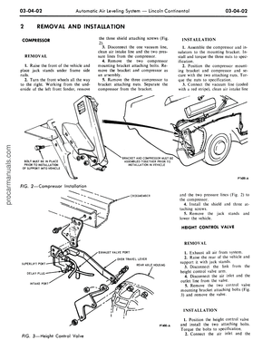
o
CO
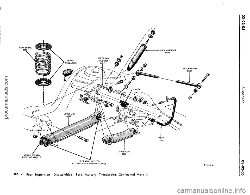
REAR SPRING
5560
!c€raMi~z'
6
VENT
TUBE
INDENT TOWARD
FRONT OF VEHICLE
UPPER ARM
5500
LEFT ARM INDENTED
BY 2 NOTCHES IN BUSHING FLANGE
Pin. ^—Rear Suspension—Disassembled—Ford, Mercury, Thunderbird, Continental Mark
c
CD
F J353-A
O
CO
6
6
Cnprocarmanuals.com
Page 82 of 413
03-02-06
Suspension
03-02-06
F1085-D
FIG.
5—Rear
Suspension—Typical—Cougar, Fairlane, Falcon,
Montego, Mustangprocarmanuals.com
Page 83 of 413
03-02-07
Suspension
03-02-07
BUSHING
5791
SPRING HANGER
5987
BUSHING
RETAINER
5A631
INSULATOR
5732
RETAINER
F 1220-C
FIG.
6—Rear
Suspension Components—Lincoln Continentalprocarmanuals.com
Page 84 of 413

03-02-08
Suspension
03-02-08
IN-VEHICLE ADJUSTMENTS AND REPAIRS
HOISTING INSTRUCTIONS
Damage to steering linkage compo-
nents and front suspension struts may
occur if care is not exercised when po-
sitioning the hoist adapters of 2 post
hoists prior to lifting the vehicle.
If a 2 post hoist is used to lift the
vehicle, place the adapters under the
lower arms or the No. 1 crossmember.
Do not allow the adapters to contact
the steering linkage. If the adapters
are placed under the crossmember, a
piece of wood (2 x 4 x 16 inches)
should be placed on the hoist channel
between the adapters. This will pre-
vent the adapters from damaging the
front suspension struts.
UPPER BALL JOINT
REPLACEMENT
FORD, MERCURY,
METEOR, THUNDERBIRD,
CONTINENTAL MARK III
1.
Raise the vehicle high enough to
provide working space, and place a
support under the lower arm. If a
chain hoist or a jack that has a nar-
row contact pad is to be used on the
bumper to raise the vehicle, distribute
the load along the bumper by using a
steel plate 3 or 4 inches long as a con-
tact pad to prevent damaging the
bumper.
2.
Remove the wheel and tire.
3.
Drill a
1/8-inch
hole through
each upper ball joint retaining rivet.
Using a large chisel, cut off the rivets.
4.
Remove the upper arm suspen-
sion bumper.
5.
Remove the cotter pin and nut
from the upper ball joint stud.
6. Place a box wrench over the
lower end of the ball joint remover
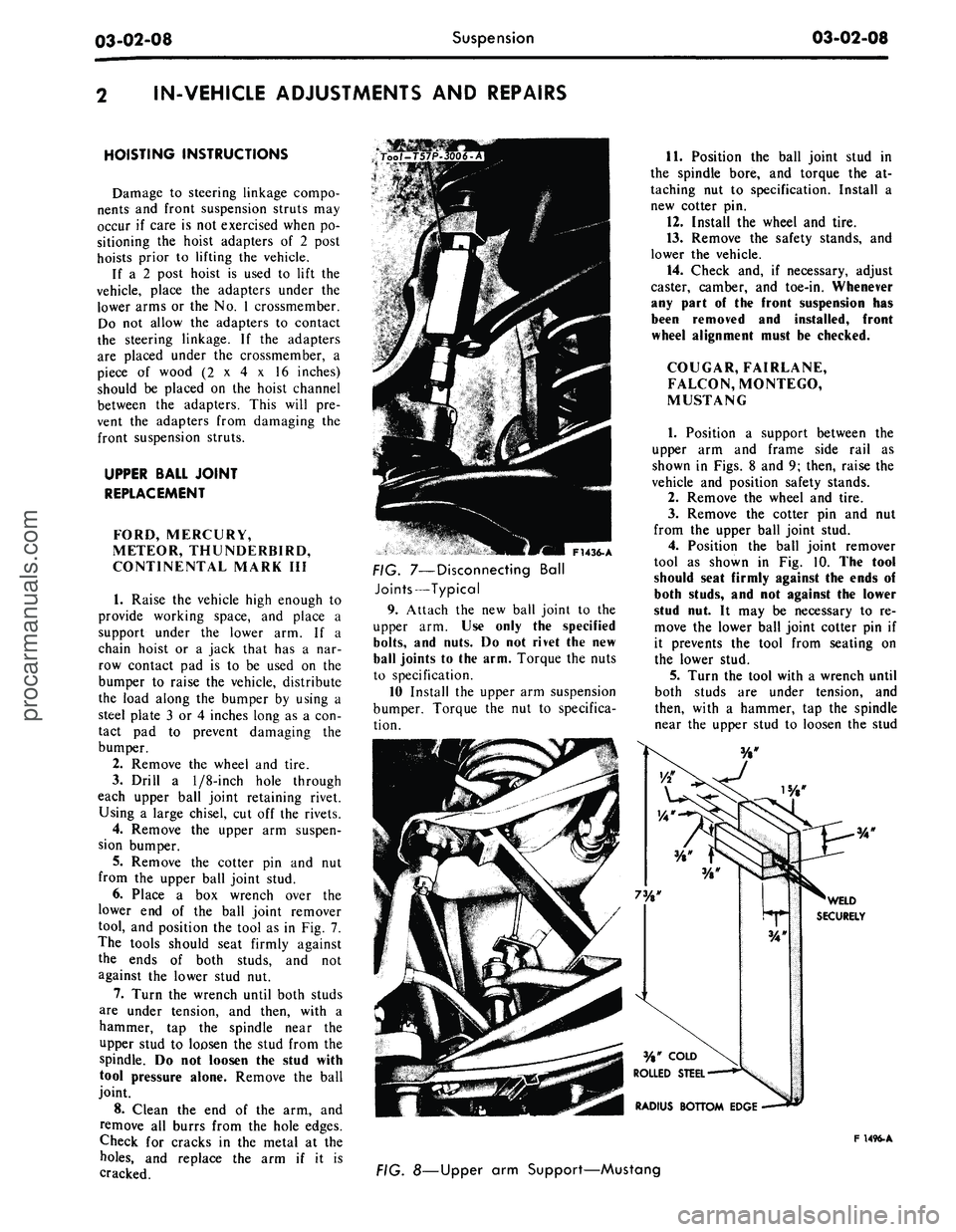
tool, and position the tool as in Fig. 7.
The tools should seat firmly against
the ends of both studs, and not
against the lower stud nut.
7.
Turn the wrench until both studs
are under tension, and then, with a
hammer, tap the spindle near the
upper stud to loosen the stud from the
spindle. Do not loosen the stud with
tool pressure alone. Remove the ball
joint.
8. Clean the end of the arm, and
remove all burrs from the hole edges.
Check for cracks in the metal at the
holes,
and replace the arm if it is
cracked.
F1436-A
FIG. 7—Disconnecting Ball
Joints—Typical
9. Attach the new ball joint to the
upper arm. Use only the specified
bolts,
and nuts. Do not rivet the new
ball joints to the arm. Torque the nuts
to specification.
10 Install the upper arm suspension
bumper. Torque the nut to specifica-
tion.
11.
Position the ball joint stud in
the spindle bore, and torque the at-
taching nut to specification. Install a
new cotter pin.
12.
Install the wheel and tire.
13.
Remove the safety stands, and
lower the vehicle.
14.
Check and, if necessary, adjust
caster, camber, and toe-in. Whenever
any part of the front suspension has
been removed and installed, front
wheel alignment must be checked.
COUGAR, FAIRLANE,
FALCON, MONTEGO,
MUSTANG
1.
Position a support between the
upper arm and frame side rail as
shown in Figs. 8 and 9; then, raise the
vehicle and position safety stands.
2.
Remove the wheel and tire.
3.
Remove the cotter pin and nut
from the upper ball joint stud.
4.
Position the ball joint remover
tool as shown in Fig. 10. The tool
should seat firmly against the ends of
both studs, and not against the lower
stud nut. It may be necessary to re-
move the lower ball joint cotter pin if
it prevents the tool from seating on
the lower stud.
5.
Turn the tool with a wrench until
both studs are under tension, and
then, with a hammer, tap the spindle
near the upper stud to loosen the stud
F 1496-A
FIG. 8—Upper arm Support—Mustangprocarmanuals.com
Page 85 of 413

03-02-09
Suspension
03-02-09
WOOD BLOCK
F
1287-A
FIG. 9—Upper
Arm
Support—
Montego, Falcon
and
Fairlane
Tool-T62F-3006-A
ARM SUPPORT
LOWER BALL JOINT
SLEEVE
Too/-T57P-3006-A
F 1157-C
FIG. TO—Loosening Ball Joint
Studs
in
Spindle—Typical
from
the
spindle.
Do not
loosen
the
stud with tool pressure alone. Raise
the stud
out of the
spindle bore.
6. Using
a
large chisel,
cut off the
three upper ball joint retaining rivets
and remove
the
ball joint.
7.
Clean
the end of the arm, and
remove
all
burrs from
the
hole edges.
Check
for
cracks
in the
metal
at the
holes,
and
replace
the arm if it is
cracked.
8. Attach
the new
ball joint
to the
upper
arm. Use
only
the
specified
bolts,
nuts,
and
washers.
Do not
rivet
the
new
ball joint
to the
arm. Torque
the nuts
to
specification (Part 3-13).
9. Position
the
lower ball joint stud
in
the
spindle bore,
and
torque
the at-
taching
nut to
specification. Install
a
new cotter
pin and
tighten
the nut if
necessary
to
line
up the
cotter
pin
hole.
Install
a new
cotter
pin in the
lower ball joint
if it was
removed.
1495-A
FIG. 11 —Shaft Centered
in
Arm—Typical
F 1494- A
FIG. 12—Torque Upper
Arm
Inner Shaft Bushings—Typical
10.
Lubricate
the
ball joint,
and in-
stall
the
wheel
and
tire. Torque
the
lug nuts
to
specification (Part 3-13).
11.
Remove
the
safety stands,
and
lower
the
vehicle.
12.
Remove
the
support from
be-
tween
the
upper
arm and
frame.
13.
Check
and, if
necessary, adjust
caster, camber,
and
toe-in.
UPPER ARM SHAFT AND/OR
BUSHING REPLACEMENT
COUGAR, FAIRLANE,
FALCON, MONTEGO,
MUSTANG
1.
Remove
the
shock absorber
and
upper mounting bracket
as an
assem-
bly.
2.
Raise
the
vehicle
on a
hoist,
in-
stall safety stands,
and
remove
the
wheel cover
or hub cap.
3.
Remove
the
grease
cap
from
the
hub;
then, remove
the
cotter
pin, nut
lock, adjusting
nut and
outer bearing
from
the hub.
4.
Pull
the
wheel, tire,
and the hub
and drum
off the
spindle
as an
assem-
bly.
5.
Install
the
spring compressor
tool (Figs.
20, 21 and 22).
6. Remove
2
upper arm-to-spring
tower attaching nuts
and
swing
the
upper
arm
outboard from
the
spring
tower.
7.
Rotate
the
inner shaft
so
that
the
studs
can be
removed. Remove
the
studs with
a
soft mallet.
8. Unscrew
the
bushings from
the
shaft
and
suspension
arm;
then,
re-
move
the
shaft from
the arm.
9. Position
the
shaft
in the. arm,
apply grease
to the new
bushings
and
O-rings,
and
install
the
bushings loose
on
the
shaft
and
arm. Turn
the
bush-
ings
so
that
the
shaft
is
exactly
cen-
tered.
The
shaft will
be
properly
cen-
tered when dimensions
A and B in
Fig.
11 are
equal.
10.
Fabricate
a
spacer from
a sec-
tion
of
3/4-inch diameter pipe
or
metal
of
comparable size
and
strength.
The
spacer should
be 6
15/16 inches long.
11.
Position
the
spacer parallel with
the inner shaft,
and
force
the
spacer
between
the
flanges
of the
upper
arm
(Fig.
12).
If
the
spacer cannot
be
forced
be-
tween
the arm
flanges due
to
excessive
distortion, replace
the
upper
arm as-
sembly.
12.
With
the
spacer positioned
in
the
arm,
torque
the
bushings
to
speci-
fication. Move
the arm on the
shaft
to
be sure that
no
binding exists, then
re-
move
the
spacer.
13.
Attach
the
suspension upper
arm
to the
underbody. Release
the
front spring.
14.
Remove
the
spring compressor
and position
the
wheel, tire,
and hub
and drum
on the
spindle.
15.
Install
the
bearing, washer,
ad-
justing
nut and nut
lock. Adjust
the
wheel bearing
as
outlined
in
Part
3-12
and install
the
cotter
pin,
grease
cap
and
hub cap or
wheel cover.
16.
Lower
the
vehicle
and
install
the shock absorber
and
upper mount-
ing bracket.
17.
Check caster, camber,
and toe-
in,
and
adjust
as
necessary (Part 3-1).
LOWER BALL JOINT
REPLACEMENT-
ARM
IN
VEHICLE
FORD, MERCURY,
METEOR, THUNDERBIRD,
CONTINENTAL MARK
III
1.
Raise
the
vehicle high enough
to
provide working space, leaving
theprocarmanuals.com
Page 86 of 413

03-02-10
Suspension
03-02-10
lower
arm
free
to
drop
as
coil spring
tension
is
eased.
If a
chain hoist
or a
jack that
has
a
narrow contact
pad is
to
be
used
on the
bumper
to
raise
the
car, distribute
the
load along
the
bumper
by
using
a
steel plate
3 or 4
inches long
as a
contact
pad to pre-
vent damaging
the
bumper.
2.
If the
ball joint
is
riveted
to the
arm, drill
a
1/8-inch
pilot hole
com-
pletely through each rivet. Then drill
off
the
rivet head through
the
pilot
hole with
a
3/8-inch drill,
and
drive
out both rivets.
3.
Position
a
jack
or
safety stand
under
the
lower
arm, and
lower
the
vehicle about
6
inches
to
offset
the
coil spring tension.
4.
Remove
the
cotter
pin
from
the
ball joint stud,
and
remove
the nut.
5.
Place
a box
wrench over
the
lower
end
of the
tool shown
in
Fig.
7,
and position
the
tool.
The
tool should
seat firmly against
the end of
both
studs,
and
not
against
the
upper stud
nut.
6. Turn
the
wrench until both studs
are under tension,
and
then, with
a
hammer,
tap the
spindle near
the
lower stud
to
loosen
the
stud from
the
spindle.
Do not
loosen
the
stud with
tool pressure alone. Remove
the
ball
joint.
7.
Clean
the end of the arm, and
remove
all
burrs from
the
hole edges.
Check
for
cracks
in the
metal
at the
holes,
and
replace
the arm if it is
cracked.
8. Position
the
stud
of
the
ball joint
to
the
spindle bore,
and
install
the at-
taching
nut
finger-tight.
9. Attach
the
ball joint
to
the
lower
arm.
Use
only
the
specified bolts
and
nuts.
Do not
rivet
the new
ball joint
to
the
arm.
Torque nuts
to
specification.
10.
Torque
the
ball joint stud
nut
to specification,
and
install
a
new cot-
ter
pin.
11.
Remove
the
jack.
12.
Check
and, if
necessary, adjust
caster, camber,
and
toe-in. Whenever
any part
of the
front suspension
has
been removed
and
installed, front
wheel alignment must
be
checked.
BALL JOINT REPLACEMENT
LINCOLN CONTINENTAL
The lower ball joint
is
riveted
to
the
lower
arm
wheras
the
upper ball joint
is bolted
to the
upper
arm.
When
re-
placing
a
ball joint,
use all the
parts
supplied
in the kit.
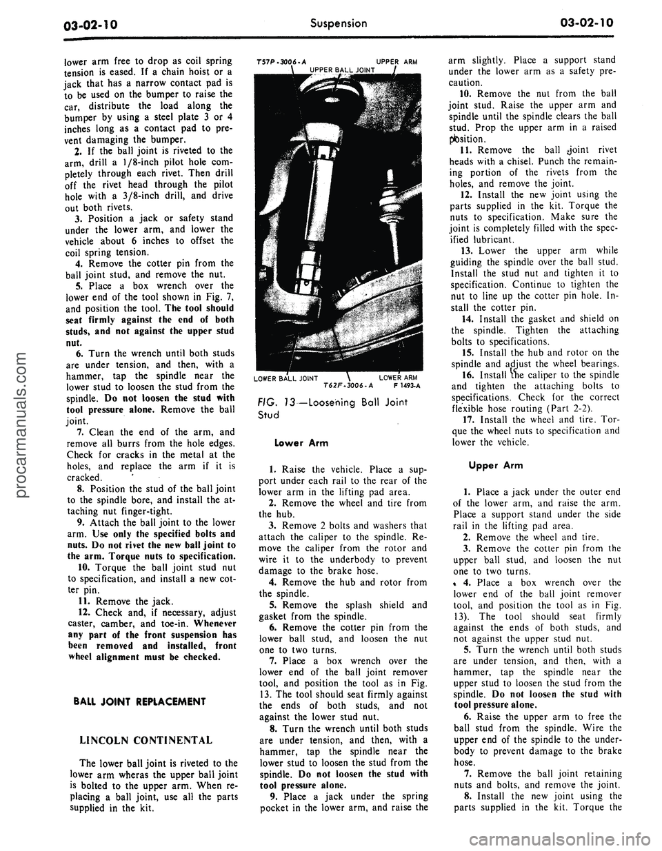
T57P-3006-A
UPPER
ARM
UPPER BALL JOINT
LOWER BALL JOINT
\
LOWER
ARM
T62F.3006-A
F
1493-A
FIG. 13— Loosening Ball Joint
Stud
Lower
Arm
1.
Raise
the
vehicle. Place
a sup-
port under each rail
to the
rear
of
the
lower
arm in the
lifting
pad
area.
2.
Remove
the
wheel
and
tire from
the
hub.
3.
Remove
2
bolts
and
washers that
attach
the
caliper
to the
spindle.
Re-
move
the
caliper from
the
rotor
and
wire
it to the
underbody
to
prevent
damage
to the
brake hose.
4.
Remove
the hub and
rotor from
the spindle.
5.
Remove
the
splash shield
and
gasket from
the
spindle.
6. Remove
the
cotter
pin
from
the
lower ball stud,
and
loosen
the nut
one
to two
turns.
7.
Place
a box
wrench over
the
lower
end of the
ball joint remover
tool,
and
position
the
tool
as in Fig.
13.
The
tool should seat firmly against
the ends
of
both studs,
and not
against
the
lower stud
nut.
8. Turn
the
wrench until both studs
are under tension,
and
then, with
a
hammer,
tap the
spindle near
the
lower stud
to
loosen
the
stud from
the
spindle.
Do not
loosen
the
stud with
tool pressure alone.
9. Place
a
jack under
the
spring
pocket
in the
lower
arm, and
raise
the
arm slightly. Place
a
support stand
under
the
lower
arm as a
safety
pre-
caution.
10.
Remove
the nut
from
the
ball
joint stud. Raise
the
upper
arm and
spindle until
the
spindle clears
the
ball
stud. Prop
the
upper
arm in a
raised
position.
11.
Remove
the
ball -joint rivet
heads with
a
chisel. Punch
the
remain-
ing portion
of the
rivets from
the
holes,
and
remove
the
joint.
12.
Install
the
new
joint using
the
parts supplied
in the kit.
Torque
the
nuts
to
specification. Make sure
the
joint
is
completely filled with
the
spec-
ified lubricant.
13.
Lower
the
upper
arm
while
guiding
the
spindle over
the
ball stud.
Install
the
stud
nut and
tighten
it to
specification. Continue
to
tighten
the
nut
to
line
up the
cotter
pin
hole.
In-
stall
the
cotter
pin.
14.
Install
the
gasket
and
shield
on
the spindle. Tighten
the
attaching
bolts
to
specifications.
15.
Install
the
hub and
rotor
on the
spindle
and
adjust
the
wheel bearings.
16.
Install
the
caliper
to
the
spindle
and tighten
the
attaching bolts
to
specifications. Check
for the
correct
flexible hose routing (Part
2-2).
17.
Install
the
wheel
and
tire.
Tor-
que
the
wheel nuts
to
specification
and
lower
the
vehicle.
Upper
Arm
1.
Place
a
jack under
the
outer
end
of
the
lower
arm,
and
raise
the arm.
Place
a
support stand under
the
side
rail
in the
lifting
pad
area.
2.
Remove
the
wheel
and
tire.
3.
Remove
the
cotter
pin
from
the
upper ball stud,
and
loosen
the nut
one
to two
turns.
%
4.
Place
a box
wrench over
the
lower
end of the
ball joint remover
tool,
and
position
the
tool
as in Fig.
13).
The
tool should seat firmly
against
the
ends
of
both studs,
and
not against
the
upper stud
nut.
5.
Turn
the
wrench until both studs
are under tension,
and
then, with
a
hammer,
tap the
spindle near
the
upper stud
to
loosen
the
stud from
the
spindle.
Do not
loosen
the
stud with
tool pressure alone.
6. Raise
the
upper
arm to
free
the
ball stud from
the
spindle. Wire
the
upper
end
of
the
spindle
to the
under-
body
to
prevent damage
to the
brake
hose.
7.
Remove
the
ball joint retaining
nuts
and
bolts,
and
remove
the
joint.
8. Install
the new
joint using
the
parts supplied
in the kit.
Torque
theprocarmanuals.com
Page 87 of 413

03-02-11
Suspension
03-02-11
nuts to specification. Make sure that
the joint is completely filled with the
specified lubricant.
9. Guide the ball joint stud into the
spindle. Install the stud nut and tor-
que it to specification. Continue to
tighten the nut to line up the cotter
pin hole. Install the cotter pin.
10.
Install the wheel and tire. Tor-
que the wheel nuts to specification.
STABILIZER REPAIR
FORD, MERCURY,
METEOR, THUNDERBIRD,
CONTINENTAL MARK III
To replace the end bushings on each
stabilizer link, use the following pro-
cedure.
1.
Raise the vehicle on a hoist.
2.
Remove the nut, washer and in-
sulator from the lower end of the sta-
bilizer bar attaching bolt.
3.
Remove the bolt and the remain-
ing washers(3) insulators (3) and the
spacer.
4.
Assemble a flat washer and a
new insulator on the bolt.
5.
Insert the bolt through the stabi-
lizer bar then install a new insulator
and a flat washer on it.
6. Install the spacer, flat washer
and another new insulator on the bolt
(Fig. 1).
7.
Insert the bolt through the lower
arm and install a new insulator and a
flat washer. Install and torque the at-
taching nut to specification.
COUGAR, FAIRLANE,
FALCON, MONTEGO,
MUSTANG
1.
Raise the vehicle high enough to
provide working space, and place sup-
ports under both front wheels.
2.
Disconnect the stabilizer from
each link. Disconnect both stabilizer
attaching brackets, and remove the
stabilizer.
3.
Coat the necessary parts of the
stabilizer with RUGLYDE or a com-
parable lubricant, and slide new insu-
lators onto the stabilizer.
4.
Secure each end of the stabilizer
bar to the lower arm making sure that
the bolt head is at the top (Fig. 2) to
eliminate interference with the brake
hose.
5.
Remove the supports and lower
the vehicle.
FRONT SUSPENSION LOWER
ARM STRUT AND/OR
BUSHING
FORD, MERCURY,
METEOR, THUNDERBIRD,
CONTINENTAL MARK III
1.
Remove the cotter pin from the
lower arm strut at the frame front
crossmember and remove the nut,
washer, and bushing from the strut.
2.
Remove nuts, washers, and bolts
attaching the strut and rubber bumper
to the lower arm (Fig. 1).
3.
Pull the strut from the frame
crossmember.
4.
Remove the crossmember rear
side bushing and washer from the
strut.
5.
Place the crossmember rear side
washer and bushing on the strut and
position the strut to the frame and
lower arm.
6. Position the rubber bumper on
the strut and install the bolts, washer,
and nuts attaching the strut to the
lower arm. Torque the nuts and bolts
to specification.
7.
Install the bushing, washer, and
nut on the strut at the front cross-
member. Tighten the nut and install
the cotter pin.
8. Check caster, camber, and toe-in
and adjust if necessary.
LOWER ARM STRUT AND/OR
BUSHING REPLACEMENT
COUGAR, FAIRLANE,
FALCON, MONTEGO,
MUSTANG
1.
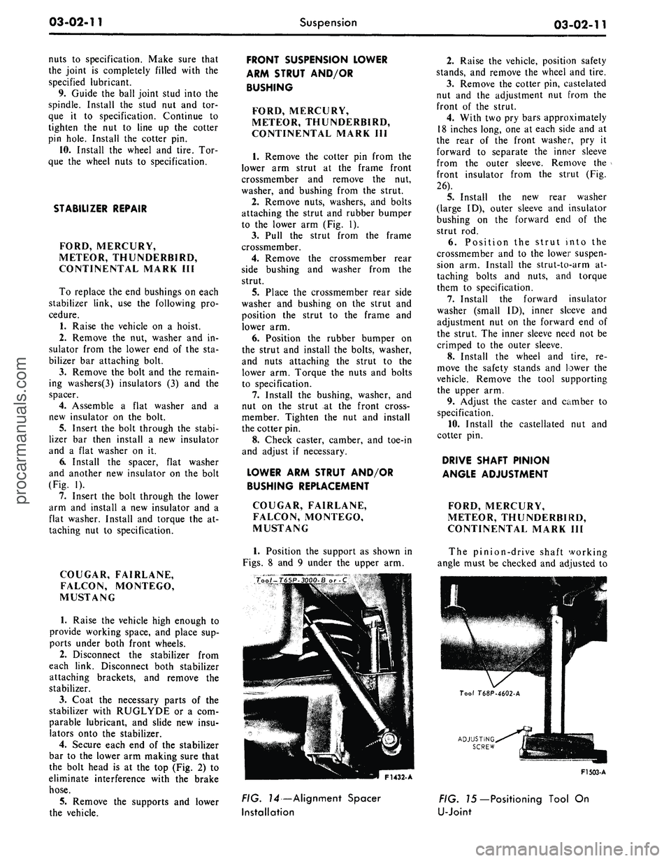
Position the support as shown in
Figs.
8 and 9 under the upper arm.
2.
Raise the vehicle, position safety
stands, and remove the wheel and tire.
3.
Remove the cotter pin, castelated
nut and the adjustment nut from the
front of the strut.
4.
With two pry bars approximately
18 inches long, one at each side and at
the rear of the front washer, pry it
forward to separate the inner sleeve
from the outer sleeve. Remove the
front insulator from the strut (Fig.
26).
5.
Install the new rear washer
(large ID), outer sleeve and insulator
bushing on the forward end of the
strut rod.
6. Position the strut into the
crossmember and to the lower suspen-
sion arm. Install the strut-to-arm at-
taching bolts and nuts, and torque
them to specification.
7.
Install the forward insulator
washer (small ID), inner sleeve and
adjustment nut on the forward end of
the strut. The inner sleeve need not be
crimped to the outer sleeve.
8. Install the wheel and tire, re-
move the safety stands and lower the
vehicle. Remove the tool supporting
the upper arm.
9. Adjust the caster and camber to
specification.
10.
Install the castellated nut and
cotter pin.
DRIVE SHAFT PINION
ANGLE ADJUSTMENT
FORD, MERCURY,
METEOR, THUNDERBIRD,
CONTINENTAL MARK III
The pinion-drive shaft working
angle must be checked and adjusted to
ADJUSTING
SCREW
F1432- A
F1503-A
FIG. 14—Alignment Spacer
Installation
FIG. 75—Positioning Tool On
U-Jointprocarmanuals.com
Page 88 of 413

03-02-12
Suspension
03-02-12
ECCENTRIC
WASHER
F1504-A
FIG. 76 —Measuring Pinion Angle
specification whenever the rear axle
has been removed.
Before checking the drive shaft pin-
ion angle, alignment height spacer
(Tool T65P-3OOO-B or C) must be in-
stalled at a height of 4.30 inches (Fig.
14).
Checking Procedure
The checking and adjusting proce-
dure must be done with the weight of
the vehicle on the front and rear sus-
pension.
UPPER ARM
KET
ECCENTRIC
WASHER
AXLE HOUSING
E1761-A
FIG.
17
—
Pinion
Angle Adjustment
1.
Position the magnetized Tool
T68P-4602-A on a U-joint bearing
cap as shown in Fig. 15.
2.
With the tool suspended straight
down and the adjusting screw to the
left, adjust the dial on the tool until
the left-hand edge of the bubble is ex-
actly on the zero line.
3.
Position the vee magnet on the
drive shaft away from welds and bal-
ance weights (Fig. 15).
4.
Position the magnetized tool
(T68P-4602-A) on the vee magnet
with the adjusting screw to the left in
the same relative position as it was on
the bearing cap (Fig. 16).
5.
Read the position of the bubbles
left-hand edge on the scale to deter-
mine the drive shaft pinion angle. The
reading should be 3 1/2 degrees plus 1
degree on Ford, Mercury or Meteor
models, 7 1/4 degrees plus 3/4 degree
on Thunderbird or Continental Mark
III models.
Adjustment
If the pinion angle is not within
specifications, adjust the pinion angle
as follows:
The upper arm-to-axle housing bolt
and two eccentric washers form an ad-
justing cam mechanism (Fig. 17)
which will tilt the axle housing to the
required angle.
1.
Loosen the upper arm pivot bolt
nuts.
2.
If the angle is less than specifica-
tions,
rotate the adjusting cam for-
ward and recheck the angle. If the
angle is more than specification, ro-
tate the adjusting cam rearward and
recheck the angle.
3.
When the axle housing is adjust-
ed in such a way that the drive shaft
angle reading is within specification,
install new pivot bolt nuts and torque
to specification (Fig. 17).
4.
Lower the vehicle and road test
for proper axle operation.
REMOVAL AND INSTALLATION
HOISTING INSTRUCTIONS
Damage to steering linkage compo-
nents and front suspension struts may
occur if care is not exercised when po-
sitioning the hoist adapters of 2 post
hoists prior to lifting the vehicle.
If a 2 post hoist is used to lift the
vehicle, place the adapters under the
lower arms or the No. 1 crossmember.
Do not allow the adapters to contact
the steering linkage. If the adapters
are placed under the crossmember, a
piece of wood (2 x 4 x 16 inches)
should be placed on the hoist channel
between the adapters. This will pre-
vent the adapters from damaging the
front suspension struts.
FRONT SPRING
REPLACEMENT
FORD, MERCURY,
METEOR, THUNDERBIRD,
CONTINENTAL MARK HI
Removal
1.
Raise the vehicle and support the
front end of the frame with jack
stands.
2.
Place a jack under the lower arm
to support it.
3.
Disconnect the lower end of the
shock absorber from the lower arm.
4.
Remove the bolts that attach the
strut and the rebound bumper to the
lower arm.
5.
Disconnect the lower end of the
sway bar stud from the lower arm.
6. Remove the nut and bolt that se-
cures the inner end of the lower arm
to the crossmember.
7.
Carefully lower the jack slowly
to relieve the spring pressure on the
lower arm, then remove the spring
(Fig. 18).
Installation
1.
Position the spring on the lower
arm so that the lower end properly
engages the seat.
2.
Raise the lower arm carefully
with a jack while guiding the inner
end to align with the bolt hole in the
crossmember. Insert the attaching bolt
in the rear of the crossmember andprocarmanuals.com