Page 209 of 413
WASHER
18041
EXISTING
HOLE
IN
SIDE RAIL
#1
NUT 372188-
S32
4137-WEDGES
SPRING-5556
INSULATOR-5732
SHACKLE
5A630
NUT34448-S8
E
1510-B
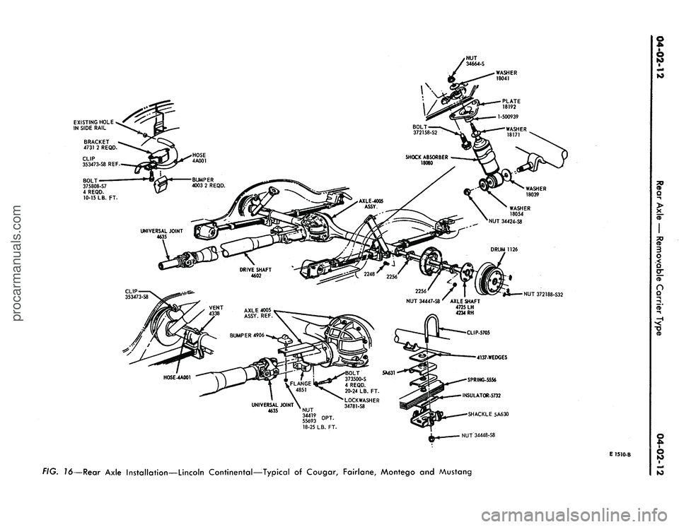
FIG. 16—Rear Axle Installation—Lincoln Continental—-Typical of Cougar, Fairlane, Montego and Mustangprocarmanuals.com
Page 210 of 413

04-02-13
Rear Axle
—
Removable Carrier Type
04-02-13
lower insulators. Torque
the
spring
clip nuts
to
specification.
2.
Place
the
brake backing plates
in
their normal position
on the
axle
housing.
3.
Install
new
axle shaft
oil
seals
with
the
tool shown
in Fig. 10.
Soak
the
new
seals
in
light weight engine
oil
(SAE
10) for 1/2
hour before install-
ing them. Installation without
use of
the proper tool will distort
the
seal
and cause leakage. Coat
the
outside
edges
of the new oil
seal with
a non-
hardening type
of
sealer such
as Per-
matex
No. 2 or its
equivalent.
4.
Install
the
axle shafts, brake
drums
and
wheels
as
outlined
in Sec-
tion
2.
5.
Attach
the
hydraulic brake line
T fitting
to the
axle housing,
and se-
cure
the
hydraulic brake line
in its re-
tainer
on the
axle housing.
6. Install vent tube
to
brake tube
junction
and
install vent hose
to
vent
tube.
7.
Raise
the
axle housing
and con-
nect
the
shock absorbers.
8. Connect
the
rear
end of the
drive
shaft
to the
axle U-joint flange, align-
ing
the
scribe marks made
on the
drive shaft
end
yoke
and the
axle
U-
joint flange.
9. Fill
the
axle with
the
proper
grade
and
amount
of
lubricant.
10.
Road test
the
vehicle.
MAJOR REPAIR OPERATIONS
DISASSEMBLY
OF
DIFFERENTIAL CARRIER
CONVENTIONAL
DIFFERENTIAL
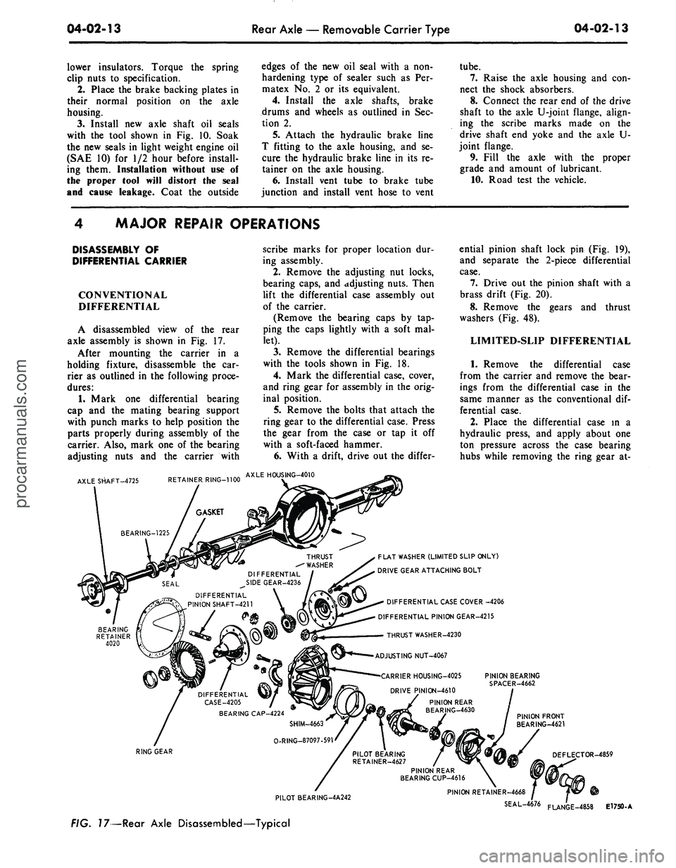
A disassembled view
of the
rear
axle assembly
is
shown
in Fig. 17.
After mounting
the
carrier
in a
holding fixture, disassemble
the car-
rier
as
outlined
in the
following proce-
dures:
1.
Mark
one
differential bearing
cap
and the
mating bearing support
with punch marks
to
help position
the
parts properly during assembly
of the
carrier. Also, mark
one of the
bearing
adjusting nuts
and the
carrier with
AXLE SHAFT-4725
RETAINER RING-1100
scribe marks
for
proper location
dur-
ing assembly.
2.
Remove
the
adjusting
nut
locks,
bearing caps,
and
adjusting nuts. Then
lift
the
differential case assembly
out
of
the
carrier.
(Remove
the
bearing caps
by tap-
ping
the
caps lightly with
a
soft
mal-
let).
3.
Remove
the
differential bearings
with
the
tools shown
in Fig. 18.
4.
Mark
the
differential case, cover,
and ring gear
for
assembly
in the
orig-
inal position.
5.
Remove
the
bolts that attach
the
ring gear
to the
differential case. Press
the gear from
the
case
or tap it off
with
a
soft-faced hammer.
6. With
a
drift, drive
out the
differ-
AXLE HOUSING-4010
DIFFERENTIAL
PINION SHAFT-4211
ential pinion shaft lock
pin (Fig. 19),
and separate
the
2-piece differential
case.
7.
Drive
out the
pinion shaft with
a
brass drift
(Fig. 20).
8. Remove
the
gears
and
thrust
washers
(Fig. 48).
LIMITED-SLIP DIFFERENTIAL
1.
Remove
the
differential case
from
the
carrier
and
remove
the
bear-
ings from
the
differential case
in the
same manner
as the
conventional
dif-
ferential case.
2.
Place
the
differential case
in a
hydraulic press,
and
apply about
one
ton pressure across
the
case bearing
hubs while removing
the
ring gear
at-
FLAT WASHER (LIMITED SLIP ONLY)
DRIVE GEAR ATTACHING BOLT
DIFFERENTIAL CASE COVER -4206
DIFFERENTIAL PINION GEAR-4215
THRUST WASHER-4230
ADJUSTING NUT-4067
CARRIER HOUSING-4025
DRIVE PINION-4610
PINION BEARING
SPACER-4662
PINION FRONT
BEARING-4621
RING GEAR
PILOT BEARING-4A242
FIG. 17—Rear Axle Disassembled—Typical
PILOT BEARING
RETAINER-4627
PINION REAR
BEARING CUP-4616
DEFLECTOR-4859
PINION RETAINER-4668
SEAL-4676
FLANGE_4858
E1750-Aprocarmanuals.com
Page 211 of 413

04-02-14
Rear Axle
—
Removable Carrier Type
04-02-14
DIFFERENTIAL
BEARING
Tool—
7
571-4220-A
T66P°4220-P
E1015-B
FIG. 18—Removing Differential
Bearing—Ford
taching bolts. Applying pressure will
contain
the
spring pressure between
the differential case
and
cover until
after
the
bolts
are
removed,
and
there-
by prevent stripping
of the
threads.
3.
Release
the
hydraulic press
ram,
and remove differential case cover.
4.
Remove
the
Belleville spring
(Fig.
54).
5.
Remove
the
steel
and the
bonded
clutch plates.
6. Remove
the
differential clutch
hub,
side gear,
and
thrust washer.
7.
Remove
the
ring gear from
the
differential case.
8. Drive
out the
differential pinion
shaft lock
pin.
9. With
a
brass drift, drive
out the
differential pinion shaft. Then remove
the pinion gears,
the
other side gear,
and thrust washers.
E 1724-A
FIG. 20—Driving
Out
Differential
Pinion Shaft
TRACTION-LOK
DIFFERENTIAL
1.
Remove
the
differential case
from
the
carrier
and
remove
the
bear-
ings from
the
differential case
in the
same manner
as the
conventional
dif-
ferential case.
2.
Remove
ten
bolts securing
the
ring gear
to the
differential case
as-
sembly.
The
ring gear must
be re-
moved
in
order
to
separate
the
case
halves.
3.
Remove
the
ring gear
by
tapping
the gear with
a
soft hammer
or
press
the gear from
the
case.
4.
Place
the
differential case
in a
press
to
load
the
bearing journals
so
that
the
pre-load
of the
springs
is ov-
ercome (approx.
1,500
lbs.).
(If a
press
is not
available,
two 7/16
inch
bolts
and
nuts
can be
used
in the
ring
gear mounting holes
(one on
each
side)
to
compress
the
case halves
to-
gether
and
overcome pre-load spring
tension.) Then, while
the
case
is
still
under pressure, loosen
the two
Allen
or Phillips head screws which hold
the
case halves together until
one or two
threads
of the
screws remain engaged.
Remove
the
case assembly from
the
press.
Tap on the
cover
to
spring
it
loose; then, remove both screws.
5.
With
the
cover facing down, lift
off
the
case. Remove
the
pre-load
spring plate
and
four pre-load springs.
6. From
the
cover remove
the
side
gear, four clutch plate
ear
guides,
clutch
hub,
friction
and
steel clutch
plates
and
shim(s).
7.
With
a
suitable drift, drive
out
the pinion shaft lock pins from
the
case.
8. With
a
brass drift, drive
out the
long pinion shaft from
the
case. Drive
from
the end
opposite
the
lock
pin
hole.
9. Remove
the two
short pinion
shafts using
a
drift, driving each shaft
from
the
center outward. Lift
out the
center block, then remove
the
pinion
gears,
thrust washers
and
side gear
and thrust washer.
10.
If the
differential bearings
are
removed,
the
bearings
can be
installed
in
one of the
following ways:
a. With
the
differential case
and
cover completely assembled.
b.
On the
case
or
cover when disas-
sembled. However, when pressing
the
bearings
on the
cover,
a
block
of
wood
or
fiber must
be
used
as
shown
in Fig.
21 in
order
to
avoid damage
to
the cover.
E 1709-A
FIG. 79—Removing Differential
Pinion Shaft Lock
Pin
DIFFERENTIAL BEARING
E1892-A
FIG. 21—Installing Differential Bearing—Traction-Lokprocarmanuals.com
Page 212 of 413

04-02-15
Rear
Axle — Removable Carrier Type
04-02-15
REMOVAL AND
DISASSEMBLY OF
DRIVE PINION AND
BEARING RETAINER
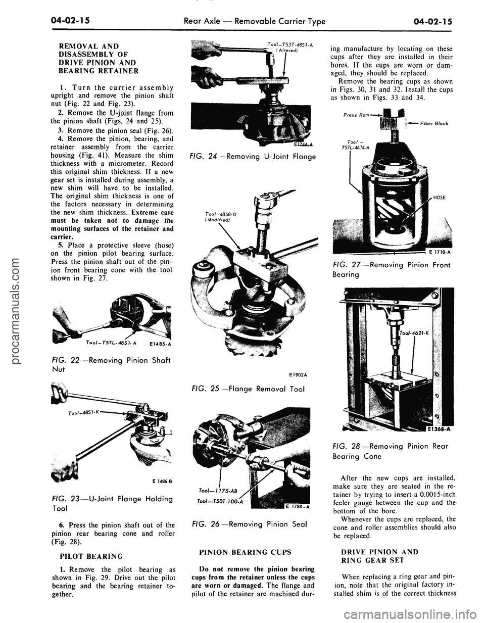
I. Turn the carrier assembly
upright and remove the pinion shaft
nut (Fig. 22 and Fig. 23).
2.
Remove the U-joint flange from
the pinion shaft (Figs. 24 and 25).
3.
Remove the pinion seal (Fig. 26).
4.
Remove the pinion, bearing, and
retainer assembly from the carrier
housing (Fig. 41). Measure the shim
thickness with a micrometer. Record
this original shim thickness. If a new
gear set is installed during assembly, a
new shim will have to be installed.
The original shim thickness is one of
the factors necessary in determining
the new shim thickness. Extreme care
must be taken not to damage the
mounting surfaces of the retainer and
carrier.
5. Place a protective sleeve (hose)
on the pinion pilot bearing surface.
Press the pinion shaft out of the pin-
ion front bearing cone with the tool
shown in Fig. 27.
O/-T57L-485
7-A
E1485-A
FIG.
22—Removing Pinion Shaft
Nut
E 1486-B
FIG. 23—
U-Joint Flange Holding
Tool
6. Press the pinion shaft out of the
pinion rear bearing cone and roller
(Fig. 28).
PILOT BEARING
1.
Remove the pilot bearing as
shown in Fig. 29. Drive out the pilot
bearing and the bearing retainer to-
gether.
FIG.
24 —
Removing
U-Joint Flange
E1902A
FIG.
25 —Flange Removal Tool
Tool-
7 7
75-AB
Tool—T50T-100-A
|E
1780.
A
FIG.
26—Removing Pinion Seal
PINION BEARING CUPS
Do not remove the pinion bearing
cups from the retainer unless the cups
are worn or damaged. The flange and
pilot of the retainer are machined dur-
ing manufacture by locating on these
cups after they are installed in their
bores.
If the cups are worn or dam-
aged, they should be replaced.
Remove the bearing cups as shown
in Figs. 30, 31 and 32. Install the cups
as shown in Figs. 33 and 34.
Press
Ram
Tool
-
757L-4674-A
Fiber Block
HOSE
\
1710-A
FIG.
27
Bearing
-Removing
Pinion Front
FIG.
28 —Removing Pinion Rear
Bearing
Cone
After the new cups are installed,
make sure they are seated in the re-
tainer by trying to insert a 0.0015-inch
feeler gauge between the cup and the
bottom of the bore.
Whenever the cups are replaced, the
cone and roller assemblies should also
be replaced.
DRIVE PINION AND
RING GEAR SET
When replacing a ring gear and pin-
ion, note that the original factory in-
stalled shim is of the correct thicknessprocarmanuals.com
Page 213 of 413

04-02-16
Rear Axle — Removable Carrier Type
04-02-16
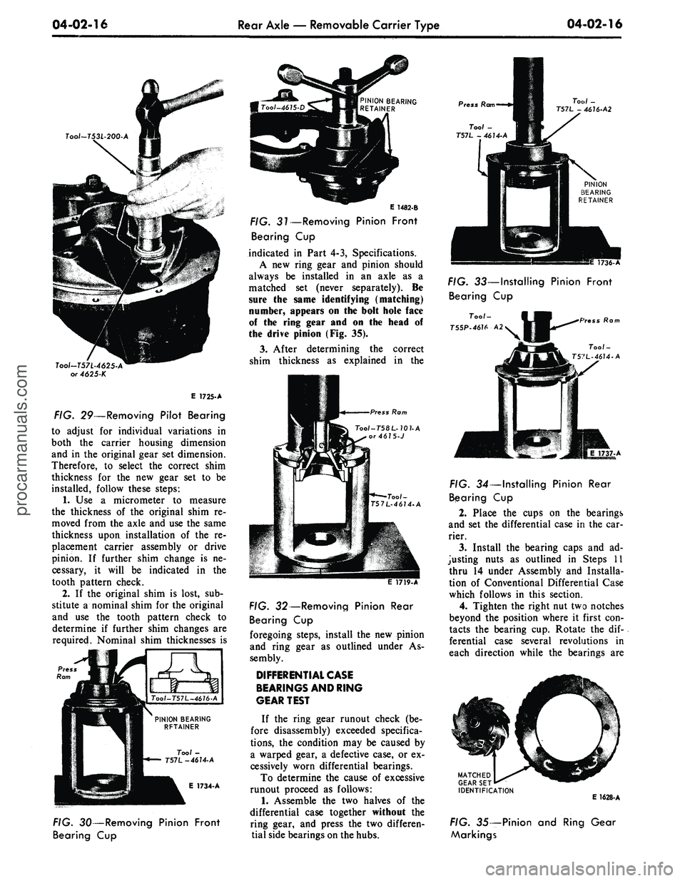
Tool~T53L-200-A
Tool-T57L-4625-A
or 4625-K
E 1725-A
FIG. 29—Removing Pilot Bearing
to adjust for individual variations in
both the carrier housing dimension
and in the original gear set dimension.
Therefore, to select the correct shim
thickness for the new gear set to be
installed, follow these steps:
1.
Use a micrometer to measure
the thickness of the original shim re-
moved from the axle and use the same
thickness upon installation of the re-
placement carrier assembly or drive
pinion. If further shim change is ne-
cessary, it will be indicated in the
tooth pattern check.
2.
If the original shim is lost, sub-
stitute a nominal shim for the original
and use the tooth pattern check to
determine if further shim changes are
required. Nominal shim thicknesses is
E 1734-A
PINION BEARING
RETAINER
E 1482-B
FIG. 31—Removing Pinion Front
Bearing Cup
indicated in Part 4-3, Specifications.
A new ring gear and pinion should
always be installed in an axle as a
matched set (never separately). Be
sure the same identifying (matching)
number, appears on the bolt hole face
of the ring gear and on the head of
the drive pinion (Fig. 35).
3.
After determining the correct
shim thickness as explained in the
ss
Rom
Too/-T58L-70?-A
or4675-J
FIG. 30—Removing Pinion Front
Bearing Cup
FIG. 32—Removing Pinion Rear
Bearing Cup
foregoing steps, install the new pinion
and ring gear as outlined under As-
sembly.
DIFFERENTIAL
CASE
BEARINGS
AND
RING
GEAR
TEST
If the ring gear runout check (be-
fore disassembly) exceeded specifica-
tions,
the condition may be caused by
a warped gear, a defective case, or ex-
cessively worn differential bearings.
To determine the cause of excessive
runout proceed as follows:
1.
Assemble the two halves of the
differential case together without the
ring gear, and press the two differen-
tial side bearings on the hubs.
Press Ram
Tool -
T57L - 4614-A
Tool -
T57L - 4676-A2
1736-/
FIG. 33—Installing Pinion Front
Bearing Cup
too;-
IB .
T55P-46U
A2V •H"^^
\
Press Ram
Tool-
T57L-46U-A
FIG. 34—Installing Pinion Rear
Bearing Cup
2.
Place the cups on the bearings
and set the differential case in the car-
rier.
3.
Install the bearing caps and ad-
justing nuts as outlined in Steps 11
thru 14 under Assembly and Installa-
tion of Conventional Differential Case
which follows in this section.
4.
Tighten the right nut two notches
beyond the position where it first con-
tacts the bearing cup. Rotate the dif-
ferential case several revolutions in
each direction while the bearings are
MATCHED
GEAR SET
IDENTIFICATION
E 1628-A
FIG. 35— Pinion and Ring Gear
Markingsprocarmanuals.com
Page 214 of 413

04-02-17
Rear Axle
—
Removable Carrier Type
04-02-17
Too/-T53L-200-A
L-462S-A
4625-K
or
4625-KA
>:
M
E 1726-A
FIG. 36—Installing Pilot Bearing
loaded
to
seat
the
bearings
in
their
cups.
This step
is
important.
5. Again loosen the- right
nut to re-
lease
the
preload. Check
to see
that
the left
nut
contacts
the
bearing
cup.
Using
the
dial indicator set-up shown
in Fig.
10,
Part 4-1, adjust the preload
to 0.008
to
0.012 case spread
for new
bearings
or
0.005
to
0.008
for the ori-
ginal bearings,
if
re-used.
6. Check
the
runout
of
the differen-
tial case flange with
a
dial indicator.
If
the
runout does
not now
exceed
specifications, install
a new
ring gear.
If
the
runout still exceeds specifica-
tions,
the
ring gear
is
true
and the
trouble
is due to
either
a
defective
case
or
worn bearings.
7. Remove
the
differential case
from
the
carrier
and
remove
the
side
bearings from
the
case.
8. Install
new
bearings
on the
case
hubs,
and
again install
the
differential
assembly
in the
carrier without
the
ring gear.
9. Check the case runout again with
the new bearings.
If the
runout
is
now
within limits,
the old
bearings were
excessively worn.
Use the new
bear-
ings
for
assembly.
If the
runout
is
still
excessive,
the
case
is
defective
and
should
be
replaced.
Press,
Ram
REAR BEARING
CONE
AND
ROLLER
Too/-
T57L-46U-A
Fiber B/oc.
DRIVE
PINION
Too/-
T57L-4621-B
1701-A
FIG. 37—Installing Pinion Rear
Bearing Cone
PRESS RAM
Tool - 4621
L
E1903A
FIG. 38—Installing Pinion Rear
Bearing Cone
ASSEMBLY
OF
DIFFERENTIAL
CARRIER
PILOT BEARING
INSTALLATION
1.
Drive
the new
pilot bearing
in-
ward until
it
bottoms,
as
shown
in
Fig.
36.
2.
Using
the
same tool indicated
in
Fig.
36,
install
the new
pilot bearing
retainer with
the
concave side
up.
COLLAPSIBLE PINION
BEARING SPACER
INSTALLATION
1.
Install
the
drive pinion rear bear-
ing cone and roller
on the
pinion shaft
(Figs.
37
m 38).
Place
a new
spacer
on the
pinion
shaft (Fig.
39).
2.
Place
the
bearing retainer
on the
pinion shaft,
and
install
the
front
bearing cone
and
roller. Press
the
front bearing cone and roller into posi-
tion
as
shown
in Fig. 40. Be
careful
not
to
crush
the
bearing spacer.
3.
Lubricate
the
O-ring with axle
lubricant and install
it in its
groove
in
the pinion retainer.
Be
careful
not to
twist
it.
Snap
the
O-ring into position.
4.
Place
the
proper shim
on the
carrier housing
and
install
the
pinion
and retainer assembly, being careful
not
to
pinch
the
O-ring (Fig.
41).
5. Install
the
pinion attaching bolts.
Torque
the
bolts
to
specification.
6. Place
the
slinger over
the
pinion
shaft
and
against
the
front bearing.
7.
Install
a new
seal
in the
bearing
retainer (Fig.
47).
8. Install
the
U-joint flange
(Fig.
49).
9. Start
a new
integral
nut and
washer
on the
pinion shaft.
Press
Ram
L*
Fiber Block
Tool-
T57L-4621
E 1712-A
FIG. 40—Installing Pinion Front
Bearing
FLANGE
O-RING
REAR BEARING
SPACER
SEAL
FRONT BEARING
RETAINER
SHIM
PINION
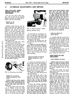
FIG. 39—Pinion
and
Bearing Retainer
PILOT
BEARING
RETAINER
PILOT
BEARING
E 1782-Aprocarmanuals.com
Page 215 of 413

04-02-18
Rear Axle — Removable Carrier Type
04-02-18
E 1195-C
FIG. 41—Removing
or
Installing
Pinion
and
Retainer Assembly
10.
Hold
the
flange with
the
tool
shown
in Fig. 22
(Ford)
or Fig. 23
(Mercury),
and
torque
the
pinion shaft
nut
to 175
ft-lbs.
Do not
exceed
175
ft-Ibs
at
this time.
11.
Check
the
pinion bearing
pre-
load
as
shown
in Fig. 42.
Correct
pre-load will
be
obtained when
the
torque required
to
rotate
the
pinion
in
the retainer
is as
specified
in
Part
4-3.
If
the
torque required
to
rotate
the pin-
ion
is
less than specified, tighten
the
pinion shaft
nut a
little
at a
time until
Inch-Pound
Torque Wrench
E1899A
FIG. 42—Checking Pinion Bearing
Preload
the proper preload
is
established.
Do
not overtighten
the nut. If
excessive
preload
is
obtained
as a
result
of
over-
tightening, replace
the
collapsible
bearing spacer.
Do
not
back
off the
pinion shaft
nut
to establish pinion bearing preload.
If
the torque
on the
pinion shaft
nut is
less than
175
ft-lbs after bearing
pre-
load
is
established,
a new
collapsible
spacer must
be
used.
SOLID PINION BEARING
SPACER INSTALLATION
The spacer
is
serviced
in 20
sizes
listed
in
Part
4-5. The
manner
of sel-
ecting
the
size spacer required
for ob-
taining correct preload
is
included
in
the following assembly procedure.
1.
Install
the
drive pinion rear bear-
ing cone
and
roller assembly
on the
pinion shaft
as
shown
in
Figs.
38 or
39.
2.
Select
a new
solid spacer
of a
larger size (0.485 inch thick),
and
slide
it over
the
pinion shaft against
the
rear bearing.
The pinion bearing preload
can be
accurately measured only when
the
pinion shaft
nut is
torqued
to 180-
220 ft-lbs.
If a
spacer smaller than
re-
quired
was
used,
the
specified
180-
220 ft-lbs torque would damage
the
bearings.
For
this reason,
the
largest
spacer should
be
tried first. Then,
if
the bearings
are too
loose,
the
size
of
the spacer
can be
decreased until
the
correct preload
is
obtained.
3.
Position
the
bearing retainer
and
cup assembly
on the
pinion shaft
and
install
the
front bearing cone
and rol-
ler. Press
the
front bearing cone
and
roller assembly into position,
as
shown
in Fig. 38.
4.
Mount
the
retainer
in a
holding
fixture
as
shown
in Fig. 23, and
place
the slinger over
the
pinion shaft
and
against
the
front bearing.
5.
Install
the
U-joint flange with
the tool shown
in Fig. 46.
6. Hold
the
flange with
the
tool
shown
in Fig. 23 or 24, and
install
the
old pinion shaft
nut.
Using
a
ft-lb
tor-
que wrench, torque
the nut to
180-220
ft-lbs.
While tightening
the nut,
rotate
the bearing retainer
to
determine
the
existance
of any
bearing preload
which will
be
indicated
by a
slight
drag
in the
rotation
of the
retainer.
DETERMINING SPACER
SIZE FROM
PRELOAD READING
1.
If
bearing drag indicates
a pre-
load condition exists, apply
an
in-lb
torque wrench
to the
pinion
nut as
shown
in Fig. 42 and
read
the
torque
required
to
turn
the
shaft. Effort
should
be
12-1/2
to
32-1/2 in-lbs.
2.
If
preload
is the
correct valve,
proceed with assembly procedure
given
in
Final Assembly
of
Pinion
and
Retainer, which follows.
2.
If
preload exists,
but is
below
specification, select
the
correct spacer
from
Fig. 43 and
install, completing
assembly
as
shown
in
Final Assembly
of Pinion
and
Retainer.
DETERMINING SPACER
SIZE FROM
END
PLAY READING
1.
If no
perceptible preload
is
felt
when rotating
the
pinion shaft, install
a dial indicator
as
shown
in Fig. 44,
so that
the
indicator point
is
resting
on
the end of the
pinion gear shaft
(companion flange
end).
2.
Use
both hands
to
squeeze
the
pinion shaft
and the
bearing retainer
together
(Fig. 45).
Record
the
endplay
reading shown
on the
dial indicator.
3.
Disassemble
the
pinion shaft
and
retainer
and
install
the
correct spacer
as shown
in Fig. 43.
4.
Proceed with assembly
of the pin-
ion shaft
and
retainer
as
directed
in
Final Assembly
of
Pinion
and
Retain-
er.
FINAL ASSEMBLY
OF
PINION
AND
RETAINER
1.
Install
the
drive pinion rear bear-
ing cone
and
roller assembly
on the
AS
END
PLAY
READS
(10/1000 inch)
USE THIS
SPACER
0
0.481
1
0.480
2
0.479
3
0.478
4
0.476
If there
is no end
play
and
preload
on the
bearings
IF PRELOAD READS
(in-lbs.)
USE THIS SPACER
2-11
0.482
12-20
0.483
5
0.476
6
0.474
7
0.474
8
0.472
9
0.472
10
0.470
11
0.470
12
0.468
13
0.468
14
0.466
15
0.465
exists:
21-30
0.484
31-45
0.485
FIG. 43— Solid Spacer Selectionprocarmanuals.com
Page 216 of 413

04-02-19
Rear Axle — Removable Carrier Type
04-02-19
POINTER RESTING ON
PINION NUT
E 1505-B
FIG.
44
— End Play Indicator
Installation
pinion shaft as shown in Figs. 37 and
38.
2.
Slide the correct spacer over the
pinion shaft against the rear bearing.
3.
Position the bearing retainer and
cup assembly on the pinion shaft and
install the front bearing cone and rol-
ler. Press the front cone and roller
into position, as shown in Fig. 46.
4.
Lubricate a new O-ring with axle
lubricant and install it in the groove
provided in the pinion retainer. Be
careful not to twist the O-ring. Install
it by snapping it into place.
5.
Place the proper shim on the
carrier housing and install the pinion
and retainer assembly, being careful
not to pinch the O-ring (Fig. 41).
6. Install the pinion retainer bolts.
Torque the bolts to specification.
7.
Place the slinger over the pinion
shaft and against the front bearing.
Tool - 4858-
E
E 1197-D
FIG. 46—Installing
U-Joint
Flange
8. Install a seal in the bearing re-
tainer, (Fig. 47).
9. Start a new integral nut and
washer on the pinion shaft.
10.
Hold the companion flange with
the tool shown in Fig. 20 or 22 and
torque the pinion nut to specifications
(200 ft-lbs).
11.
With a new seal installed pin-
ion bearing preload should now read
17 to 32 in-lbs for new pinion bearings
and new seal, or 8 to 14 in-lbs for ori-
ginal bearings and a new seal.
ASSEMBLY AND
INSTALLATION OF
DIFFERENTIAL CASE
Conventional
Differential Case
1.
Place a side gear and thrust
washer in the differential case bore
E 1506-B
E 1629-A
FIG. 45— Checking Pinion End
Play
FIG. 47—Installing Oil Seal
(Fig. 48). Lubricate all differential
parts liberally with axle lubricant dur-
ing assembly.
2.
With a soft-faced hammer, drive
the differential pinion shaft into the
case only far enough to retain a pin-
ion thrust washer and pinion gear.
3.
Place the second pinion and
thrust washer in position, and drive
the pinion shaft into place. Carefully
line up the pinion shaft lock pin holes.
4.
Place the second side gear and
thrust washer in position (Fig. 48),
and install the cover on the differen-
tial case. Install the pinion shaft lock
pin. A pinion or axle shaft spline can
be inserted in the side gear spline to
check for free rotation of the differen-
tial gears.
5.
Insert two 7/16 (N.F.) bolts two
inches long through the differential
case flange, and thread them three or
four turns into the ring gear as a
guide in aligning the ring gear bolt
holes.
Press or tap the ring gear into
position.
6. Install and tighten the ring gear
bolts and washers evenly, and torque
them alternately across the gear to
specification.
7.
If the differential bearings have
been removed, press them on as
shown in Figs. 49 and 50.
8. Wipe a thin coating of lubricant
on the bearing bores so that the dif-
ferential bearing cups will move easily.
9. Place the cups on the bearings.
If the gear set is of the non-hunting or
partial non-hunting type, assemble the
differential case and ring gear assem-
bly in the carrier so that the marked
tooth on the pinion indexes between
the marked teeth on the ring gear as
shown in Fig. 51.
In almost every case of improper
assembly (gears assembled out of
time),
the noise level and probability
of failure will be higher than they
would be with properly assembled
gears.
When installing the hunting type
gear set (no timing marks), assemble
the differential case and ring gear as-
sembly in the carrier without regard
to the matching of any particular gear
teeth.
10.
Slide the assembly along the
bores until a slight amount of back-
lash is felt between the gear teeth.
11.
Set the adjusting nuts in the
bores so that they just contact the
bearing cups. The nuts should be en-
gaged about the same number of
threads on each side.
12.
Carefully position the bearing
caps on the carrier. Match the marks
made when the caps were removed.procarmanuals.com