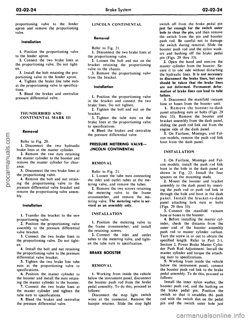
1969 FORD MUSTANG open hood
[x] Cancel search: open hoodPage 43 of 413

02-02-24
Brake
System
02-02-24
proportioning valve to the fender
apron and remove the proportioning
valve.
Installation
1.
Position the proportioning valve
to the fender apron.
2.
Connect the two brake lines at
the proportioning valve. Do not tight-
en.
3.
Install the bolt retaining the pro-
portioning valve to the fender apron.
4.
Tighten the brake line tube nuts
at the proportioning valve to specifica-
tions.
5.
Bleed the brakes and centralize
pressure differential valve.
THUNDERBIRD AND
CONTINENTAL MARK III
Removal
Refer to Fig. 20.
1.
Disconnect the two hydraulic
brake lines at the master cylinder.
2.
Remove the two nuts retaining
the master cylinder to the booster and
remove the master cylinder for clear-
ance.
3.
Disconnect the two brake lines at
the proportioning valve.
4.
Remove the bolt and nut retain-
ing the proportioning valve to the
pressure differential valve bracket and
remove the proportioning valve assem-
bly.
Installation
1.
Transfer the bracket to the new
proportioning valve.
2.
Position the proportioning valve
assembly to the pressure differential
valve bracket.
3.
Connect the two brake lines to
the proportioning valve. Do not tight-
en.
4.
Install the bolt and nut retaining
the proportioning valve to the pressure
differential valve bracket.
5.
Tighten the two brake line tube
nuts at the proportioning valve to
specifications.
6. Position the master cylinder to
the booster and install the nuts retain-
ing the master cylinder to the booster.
7.
Connect the two brake lines at
the master cylinder and tighten the
tube nuts to specifications.
8. Bleed the brakes and centralize
the pressure differential valve.
LINCOLN CONTINENTAL
Removal
Refer to Fig. 21.
1.
Disconnect the two brake lines at
the proportioning valve.
2.
Loosen the bolt and nut on the
bracket retaining the proportioning
valve to the chassis.
3.
Remove the proportioning valve
from the bracket.
Installation
- 1. Position the proportioning valve
in the bracket and connect the two
brake lines. Do not tighten.
2.
Tighten the bolt and nut on the
bracket.
3.
Tighten the tube nuts on the
brake lines at the proportioning valve
to specifications.
4.
Bleed the brakes and centralize
the pressure differential valve.
PRESSURE METERING VALVE—
LINCOLN CONTINENTAL
REMOVAL
Refer to Fig. 21.
1.
Loosen the tube nuts connecting
the inlet and outlet tubes at the me-
tering valve, and remove the tubes.
2.
Remove the two screws retaining
the metering valve to the frame
crossmember, and remove the me-
tering valve. The metering valve is ser-
viced as an assembly only.
INSTALLATION
1.
Position the metering valve to
the frame crossmember, and install
the retaining screws.
2.
Connect the inlet and outlet
tubes to the metering valve, and tight-
en the tube nuts to specification.
BRAKE BOOSTER
REMOVAL
1.
Working from inside the\ vehicle
below the instrument panel, disconnect
the booster push rod from the brake
pedal assembly. To do this, proceed as
follows:
Disconnect the stop light switch
wires at the connector. Remove the
hairpin retainer. Slide the stop light
switch off from the brake pedal pin
just far enough for the switch outer
hole to clear the pin, and then remove
the switch from the pin and booster
push rod. Be careful not to damage
the switch during removal. Slide the
booster push rod and the nylon wash-
ers and bushing off the brake pedal
pin (Figs. 29 thru 33).
2.
Open the hood and remove the
master cylinder from the booster. Se-
cure it to one side without disturbing
the hydraulic lines. It is not necessary
to disconnect the brake lines, but care
should be taken that the brake lines
are not deformed. Permanent defor-
mation of brake lines can lead to tube
failure.
3.
Disconnect the manifold vacuum
hose or hoses from the booster unit.
4.
Remove the booster-to-dash
panel attaching nuts or bolts (Figs. 29
thru 33). Remove the booster and
bracket assembly from the dash panel,
sliding the push rod link out from the
engine side of the dash panel.
5.
On Fairlane, Montego, and Fal-
con models, remove the push rod link
boot from the dash panel.
INSTALLATION
1.
On Fairlane, Montego and Fal-
con models, install the push rod link
boot in the hole in the dash panel as
shown in Fig. 23. Install the four
spacers on the mounting studs.
2.
Mount the booster and bracket
assembly to the dash panel by insert-
ing the push rod or push rod link in
through the hole and boot in the dash
panel. Install the bracket-to-dash
panel attaching lock nuts or bolts
(Figs.
29 thru 33).
3.
Connect the manifold vacuum
hose or hoses to the booster.
4.
Before installing the master cyl-
inder, check the distance from the
outer end of the booster assembly
push rod to master cylinder surface.
Turn the screw in or out to obtain the
specified length. Refer to Part 2-1,
Section 2, Power Brake Master Cylin-
der Push Rod Adjustment. Install the
master cylinder and torque the attach-
ing nuts to specifications.
5.
Working from inside the vehicle
below the instrument panel, connect
the booster push rod link to the brake
pedal assembly. To do this, proceed as
follows:
Install the inner nylon washer, the
booster push rod, and the bushing on
the brake pedal pin. Position the
switch so that it straddles the push
rod with the switch slot on the pedal
pin and the switch outer hole justprocarmanuals.com
Page 120 of 413

03-05-07
Steering Columns And Linkage
03-05-07
the steering column
(F in Fig. 8).
7.
Disconnect
the
transmission shift
rod
at the
shift tube.
8. Working under
the
hood, install
the aligning spacer (Fig.
9)
around
the
visible portion
of the
steering shaft
and slide
it up the
shaft into
the
steer-
ing column.
It may be
necessary
to
move
the
shaft back
and
forth
to
com-
pletely install
the
spacer.
9.
At
this point
the
steering column
assembly, being loose,
may
have
dropped toward
the
steering gear
grounding
the
steering shaft
on the
steering gear input shaft.
To
properly
establish
the
steering shaft
to
steering
gear clearance, insert
a 1/8
diameter
rod
or
drill through
the
opening
in the
upper half
of the
flex coupling.
10.
Tighten
to a
snug
fit
(approxi-
mately
2-3
ft-lb)
the
nuts retaining
the
toe plates
to the
dash panel
(B in Fig.
8).
11.
If the
aligning spacer cannot
be
rotated freely,
the
dash panel holes
must
be
filed
or
reamed
for
greater
travel
(as
mentioned
in the
second
paragraph
at the
beginning
of
this
procedure).
12.
Tighten
all
nuts
and
bolts
(noted
as C, D and E in
Fig.
8) in the
passenger compartment
to a
snug
fit
(approximately 2-3 ft-lb). Again check
aligning spacer
for
looseness. Perform
these tightening operations
in
alpha-
betical order.
13.
Tighten
the
lateral adjustment
bolt
(F in Fig. 8) to
snug
fit.
Again
check
the
aligning spacer
for
loose-
ness.
14.
Tighten
all
bolts and nuts
to the
proper torque value (listed
in Fig. 8)
in alphabetical order.
15.
Remove
the
steering shaft
al-
igning spacer.
16.
Remove
the 1/8
diameter
rod or
drill previously inserted
in the
flex
coupling.
17.
Reinstall
the
trim
at the
instru-
ment panel
to
steering column mount-
ing.
LINCOLN CONTINENTAL
If
a
condition
of
high shift
or
steer-
ing effort
is
experienced
it may be
caused
by
improper alignment
of the
energy absorbing steering column.
The
following procedures outline
the
steps
necessary
to
correctly realign either
fixed
or
tilt columns:
1.
Disconnect
the
battery.
2.
Loosen four
toe
plate attaching
nuts (Fig.
10).
3.
Loosen
one toe
plate
to
steering
column clamp bolt
and nut.
Check
alignment
of
steering shaft
to
shift
-HANDLE PORTION
2-3/4"
-*- 3/4"
BEND AROUND
STEERING SHAFT
DIMENSION
A:
STANDARD COLUMN 7/16"
TILT WHEEL COLUMN
1-1/8"
•2-3/4
FABRICATE ALIGNING SPACER OUT OF
PLASTIC SHIPPING COLLAR PROVIDED
ON SERVICE DRIVESHAFTS, OR OUT
OF
1/32"—1/16" CARDBOARD
STEERING SHAFT
ALIGNMENT SPACER-BEND AROUND
STEERING SHAFT (DIMENSION
A)
AND
SLIDE UP THE SHAFT INTO COLUMN
G1537-A
FIG. 9—Aligning Spacer Fabrication
and
Insertion
BRAKE PEDAL
SUPPORT BRACKET
PART
A-TOE PLATE
B-CLAMP
C-C0LUMN BRACKET
D-BRAKE PEDAL
SUPPORT BRACKET
TORQUE VALUE
8-12 FT. LB.
3-5 FT. LB.
10-15
FT.
LB.
8-12 FT. LB.
G1541-A
FIG. 10—Steering Column Alignment Locations
and
Torque
Specifications—Lincoln Continentalprocarmanuals.com
Page 169 of 413

03-11-01
Eaton Power Steering Pump
03-11-01
PART 3-11 Eaton Power Steering Pump
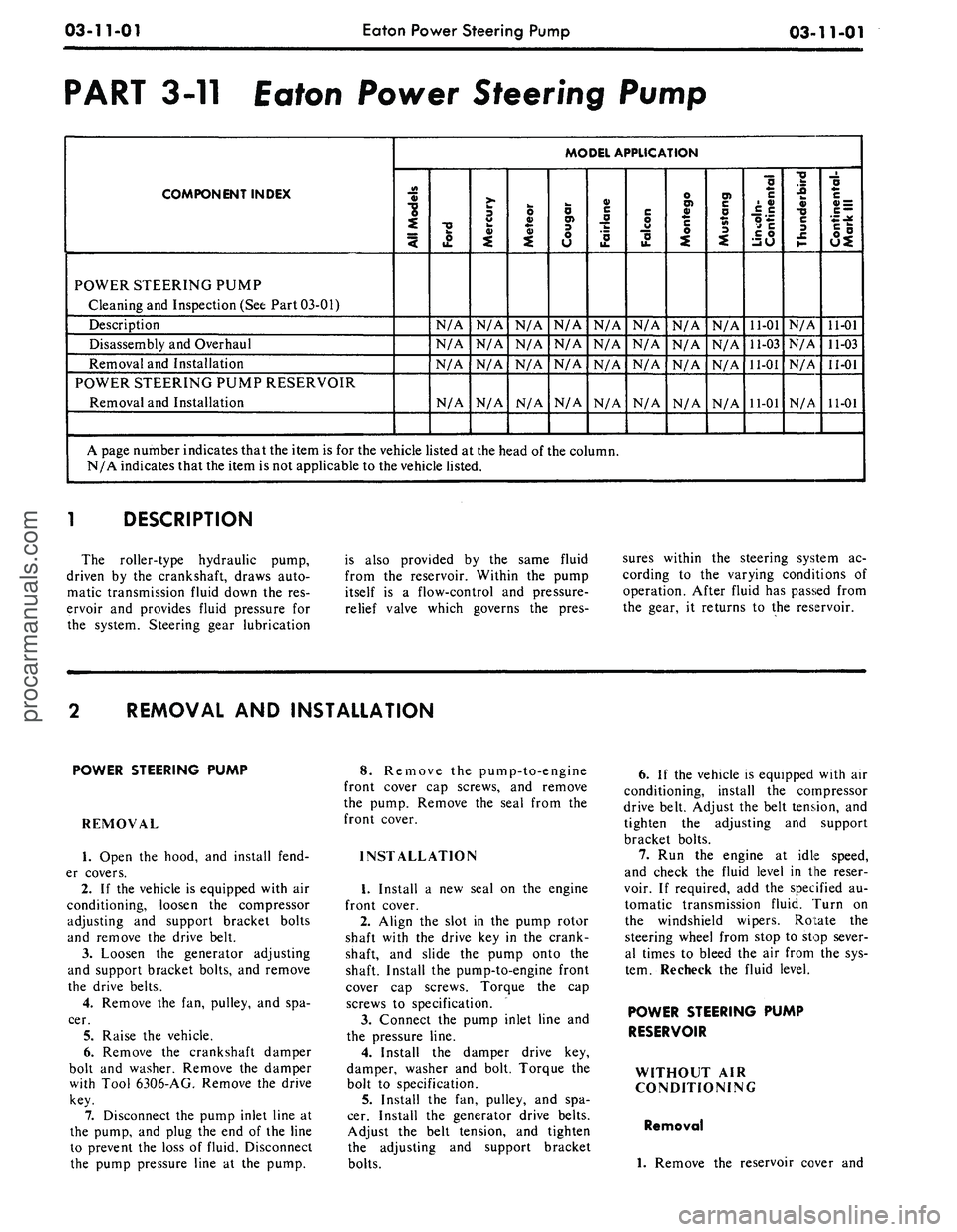
COMPONENT INDEX
MODEL APPLICATION
3
§>
"o
4
POWER STEERING PUMP
Cleaning and Inspection (See Part 03-01)
Description
N/A
N/A
N/A
N/A
N/A
N/A
N/A
N/A
11-01
N/A
11-01
Disassembly and Overhaul
N/A
N/A
N/A
N/A
N/A
N/A
N/A
N/A
11-03
N/A
11-03
Removal and Installation
N/A
N/A
N/A
N/A
N/A
N/A
N/A
N/A
11-01
N/A
11-01
POWER STEERING PUMP RESERVOIR
Removal and Installation
N/A
N/A
N/A
N/A
N/A
N/A
N/A
N/A
11-01
N/A
11-01
A page number indicates that the item is for the vehicle listed at the head of the column.
N/A indicates that the item is not applicable to the vehicle listed.
l
DESCRIPTION
The roller-type hydraulic pump,
driven by the crankshaft, draws auto-
matic transmission fluid down the res-
ervoir and provides fluid pressure for
the system. Steering gear lubrication
is also provided by the same fluid
from the reservoir. Within the pump
itself is a flow-control and pressure-
relief valve which governs the pres-
sures within the steering system ac-
cording to the varying conditions of
operation. After fluid has passed from
the gear, it returns to the reservoir.
REMOVAL AND INSTALLATION
POWER STEERING PUMP
REMOVAL
1.
Open the hood, and install fend-
er covers.
2.
If the vehicle is equipped with air
conditioning, loosen the compressor
adjusting and support bracket bolts
and remove the drive belt.
3.
Loosen the generator adjusting
and support bracket bolts, and remove
the drive belts.
4.
Remove the fan, pulley, and spa-
cer.
5.
Raise the vehicle.
6. Remove the crankshaft damper
bolt and washer. Remove the damper
with Tool 6306-AG. Remove the drive
key.
7.
Disconnect the pump inlet line at
the pump, and plug the end of the line
to prevent the loss of fluid. Disconnect
the pump pressure line at the pump.
8. Remove the pump-to-engine
front cover cap screws, and remove
the pump. Remove the seal from the
front cover.
INSTALLATION
1.
Install a new seal on the engine
front cover.
2.
Align the slot in the pump rotor
shaft with the drive key in the crank-
shaft, and slide the pump onto the
shaft. Install the pump-to-engine front
cover cap screws. Torque the cap
screws to specification.
3.
Connect the pump inlet line and
the pressure line.
4.
Install the damper drive key,
damper, washer and bolt. Torque the
bolt to specification.
5.
Install the fan, pulley, and spa-
cer. Install the generator drive belts.
Adjust the belt tension, and tighten
the adjusting and support bracket
bolts.
6. If the vehicle is equipped with air
conditioning, install the compressor
drive belt. Adjust the belt tension, and
tighten the adjusting and support
bracket bolts.
7.
Run the engine at idle speed,
and check the fluid level in the reser-
voir. If required, add the specified au-
tomatic transmission fluid. Turn on
the windshield wipers. Rotate the
steering wheel from stop to stop sever-
al times to bleed the air from the sys-
tem. Recheck the fluid level.
POWER STEERING PUMP
RESERVOIR
WITHOUT AIR
CONDITIONING
Removal
1.
Remove the reservoir cover andprocarmanuals.com