1969 FORD MUSTANG load capacity
[x] Cancel search: load capacityPage 181 of 413

03-13-02
Specifications
03-13-02
POWER STEERING PUMP
SERVICE
SPECIFICATIONS
Description
Pump Rotor Shaft End Play
Max. Torque Allowed
to
Rotate Rotor Shaft
Stamped Housing to Plate
Assy. Screw and Washer Assy.
Reservoir
to
Stamped Housing
Nut
Cam Ring to Pressure Plate
Screw
Housing to Cover Screw
Ford-Thompson
.017 in. Max.-.003 in. Min.
15 In-Lb.
28-32 Ft.-Lb.
43-47 Ft.-Lb.
_
-
Eaton
—
_
-
—
20 In-Lb.
15-20 Ft,-Lb.
FORD-THOMPSON POWER STEERING
PUMP
TORQUE
LIMITS (FT-LBS)
Description
Pump Rear Mounting Nut
Pressure Hose Nut
Pump Attaching Nuts
Bracket
to
Engine Attaching Nuts
6-Cyl.
302-351 CID
390,427,428,429 CID
Bracket
to
Cylinder Head
Belt Adjustment Bolt
Rear Support Bracket Attaching Nuts
Bracket
to
Engine Adapter
Engine Adapter
to
Engine
Engine Adapter
to
Pump
240 CID
170-200 CID
170-200 CID
250 CID
250 CID
Ford,
Mercury,
Meteor,
Thunderbird
14-18
20-30
25-35
1216
18-25
30-40
25-35
-
45-60
-
-
-
-
Cougar, Falcon,
Fairlane, Montego,
Mustang
20-30
20-30
30-40
7-10
18-25
30-40
25-35
25-35
-
25-35
17-25
30-40
25-35
INTEGRAL
POWER
STEERING GEAR SPECIFICATIONS
Description
Type
Ratio
Turns of Steering Wheel (Lock
to
Lock-Linkage Disconnected)
Fluid Specifications
Fluid Capacity (Included in Pump Reservoir Fill)
Phosphorescent Dye Additive (For Leak Detection)
Sector Shaft End Play -Linkage Disconnected
Sector Shaft Mesh Load. Total Over Mechanical Center
Position.
Must beCDGreater Than Worm
Bearing Preload Torque, Shown Below
Worm Bearing Preload
Clearance Between Valve Spool
&
Retaining Ring
Pressure Variation Between Right
&
Left Turn (At 250
P.S.I.)
-
Check Efforts Each Side
of
Center
Clearance Between Inner Sector Seal and Housing
Ford Design
(XR-«0)
Saginaw
Design
Recirculating Ball Torsion Bar
17:1
4
17.5:1
41/8
M-2C33-F
1.6 Pints (Approx.)
M99B103-A(4 0z. per quart)
None
14 In Lb (Max)
(Exc. Lincoln)
17
In
Lb (Max.)
(Lincoln)
2-7 la
U)
.0035-.0005"
Preferable .002"
4
In
Lb Max.
Variation
.025"
.002"
Max.
14
In
Lb (Max)
4-7 In Lb®
_
—
-
©8-9 In Lb (XR-50 Exc. Lincoln) 11-12 In Lb
for
Uncoln,
4-8 In
Lb
for
Saginaw Gear.
® 3 In Lb in Excess of Valve Assy. Drag Total Worm Bearing Preload and Seal Drag
not to
Exceed
8 In
Lb.procarmanuals.com
Page 182 of 413

03-13-03
Specifications
03-13-03
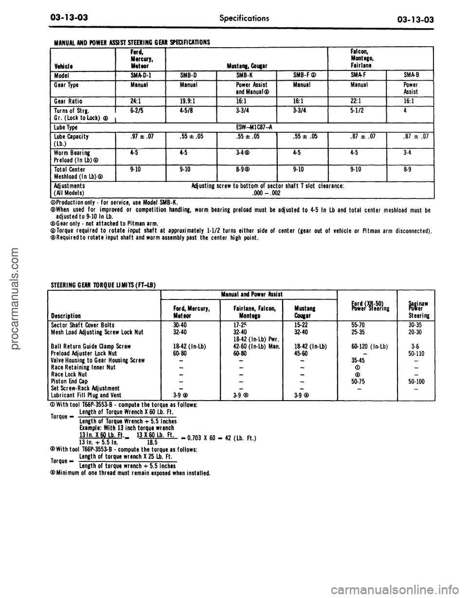
MANUAL AND POWER
Vehicle
Model
Gear Type
Gear Ratio
Turns of
Strg.
Gr. (Lock to Lock)
®
Lube Type
Lube Capacity
(Lb.)
Worm Bearing
Preload (In Lb)®
Total Center
Meshload(lnLb)®
Adjustments
(All Models)
ASSIST STEERING GEAR SPECIFICATIONS
Ford,
Mercury,
Meteor
SM/VD-1
Manual
24:1
6-2/5
.97
±
.07
4-5
9-10
SMB-D
Manual
19.9:1
4-5/8
.55
±
.05
4-5
9-10
Adjusting
Mustang, Cougar
SMBK
Power Assist
and Manual®
16:1
3-3/4
ESW-M1C87-A
.55
±
.05
3-4®
8-9®
screw to bottom
of
sector
.000 -.002
SMB-F®
Manual
16:1
3-3/4
.55
±
.05
4-5
9-10
shaft T slot clearance:
Falcon,
Mont ego,
Fairlane
SMA-F
Manual
22:1
5-1/2
.87
±
.07
4-5
9-10
SMA-B
Power
Assist
16:1
4
.87
±
.07
3-4
8-9
©Production only
-
for service, use Model SMB-K.
®When used
for
improved
or
competition handling, worm bearing preload must
be
adjusted
to
4-5
In
Lb and total center meshload must
be
adjusted to 9-10 In Lb.
®Gear only
-
not attached to Pitman arm.
0Torque required
to
rotate input shaft
at
approximately 1-1/2 turns either side
of
center (gear
out of
vehicle
or
Pitman arm disconnected).
©Requiredto rotate input shaft and worm assembly past
the
center high point.
STEERING GEAR TORQUE UMITS(FT-LB)
Description
Sector Shaft Cover Bolts
Mesh Load Adjusting Screw Lock Nut
Ball Return Guide Clamp Screw
Preload Adjuster Lock Nut
Valve Housing
to
Gear Housing Screw
Race Retaining Inner Nut
Race Lock Nut
Piston End Cap
Set Screw-Rack Adjustment
Lubricant Fill Plug and Vent
Manual and Power Assist
Ford,
Mercury,
Meteor
30-40
32-40
18-42 (In-Lb)
60-80
3-9®
Fairlane, Falcon,
Montego
17-2?
32-40
18-42 (In-Lb) Pwr.
42-60 (In-Lb) Man.
60-80
3-9®
Mustang
Cougar
15-22
32-40
18-42 (In-Lb)
45-60
3-9®
Power steering
55-70
25-35
60-120 (In-Lb)
35-45
(D
®
50-75
Steering
30-35
20-30
3-6
50-110
50-100
® With tool T66P-3553-B
•
compute the torque as follows:
Length
of
Torque Wrench
X
60 Lb.
Ft.
°rque
"
Length
of
Torque Wrench
+
5.5 Inches
Example: With 13 inch torque wrench
13ln.
X
60 Lb. Ft. 13
X
60 Lb.
Ft.
13
In.
+
5.5 In.
18.5
®With tool T66P-3553-B
•
compute the torque as follows:
Length
of
torque wrench
X
25 Lb.
Ft.
Length of torque wrench
+
5.5 Inches
©Minimum
of
one thread must remain exposed when installed.
-0.703 X60- 42 (Lb.
Ft.)procarmanuals.com
Page 200 of 413

04-02-03
Rear Axle — Removable Carrier Type
04-02-03
is,
it is supported by bearings both in
front of and to the rear of the pinion
gear. Two opposed tapered roller
bearings support the pinion shaft in
front of the pinion gear with a col-
lapsible spacer for 8-3/4 inch or 9
inch ring gear, and a solid spacer used
with the 9 3/8 inch ring gear. A
straight roller (pilot) bearing supports
the pinion shaft at the rear of the pi-
nion gear. Pinion and ring gear tooth
contact is adjusted by adding or re-
moving shims from between the pinion
retainer and the carrier housing.
The differential assembly is mount-
ed on two opposed tapered roller
bearings, which are retained in the
carrier by removable caps. The entire
carrier assembly is bolted to the axle
housing.
Ball bearing assemblies (rear wheel
bearings) are pressed onto the outer
ends of the axle shafts and set in the
outer ends of the axle housing. These
bearings support the semi-floating
axle shafts at the outer ends. The
inner ends of the shafts spline to the
differential side gears. Bearing retain-
er plates hold the shafts in the hous-
ing. The left and right axle shafts are
not interchangeable, the left shaft
being shorter than the right.
CASE
COVER
BELLEVILLE
SPRING
CLUTC
HUB
STEEL
PLATES
BONDED
PLATES
E1741-A
FIG. 2—Limited-Slip Differential
LIMITED-SUP DIFFERENTIAL
The axle assembly, except for the
differential case and its internal com-
ponents, is identical to the convention-
al axle.
A constant-friction locking differen-
tial,
which employs clutch plates to
control differential action, is available
as optional equipment (Fig. 2).
Four steel clutch plates are locked
into the differential cover. Three
bronze, bonded clutch plates are
splined to a clutch hub which, in turn,
is splined to the left axle shaft. A
Belleville spring washer maintains a
constant pressure between the steel
and bonded clutch plates so that the
clutch is always engaged.
TRACTION-LOK
DIFFERENTIAL
The Traction-Lok (torque sensitive)
locking differential (Fig. 3) employs a
multiple disc clutch to control differ-
ential action. Shim(s), which control
side gear mounting distance, four
steel, four friction and one composite
plate (steel on one side and friction
material on the other) stacked on a
clutch hub, and four ear guides are
housed in the differential cover. Lo-
cated in the differential case between
the side gears is a one-piece pre-load
plate and block (four-pinion) and four
calibrated pre-load springs, which
apply an initial force to the clutch
pack. Additional clutch capacity is
derived from the side gear thrust
loads.
The four friction plates are
splined to the clutch hub which in turn
is splined to the left axle shaft, and
the eared steel plates are dogged to
the case; thus, the clutch is always en-
gaged.
PINION SHAFT
4211
PINION SHAFT
RETAINING PINS
359475-S
DIFFERENTIAL
CASE-4204
CASE-TO-COVER
RETAINING SCREWS
50025-S2
SIDE GEAR
THRUST WASHER
4228
CENTER BLOCK
(SHORT PINION PINION
SHAFT SEAT) SHAFT
4420 44207
7
PINION GEAR
THRUST WASHER
4230
PINION GEARS
4215
PINION GEAR
THRUST WASHER
4230
PINION SHAFT
44207
SHIM(S)
(AS REQ'D.)
4A324
DIFFERENTIAL
CASE COVER
4204
PINION GEAR
THRUST WASHER
4230
PRE-LOAD SPRING
PINION GEAR PLATE-4A326
THRUST WASHER
4230
CLUTCH PLATE
EAR GUIDES
(4)
4A323
E 1896-A
FIG. 3—Traction-Lok Differentialprocarmanuals.com
Page 406 of 413

07-05-06
Specifications
07-05-06
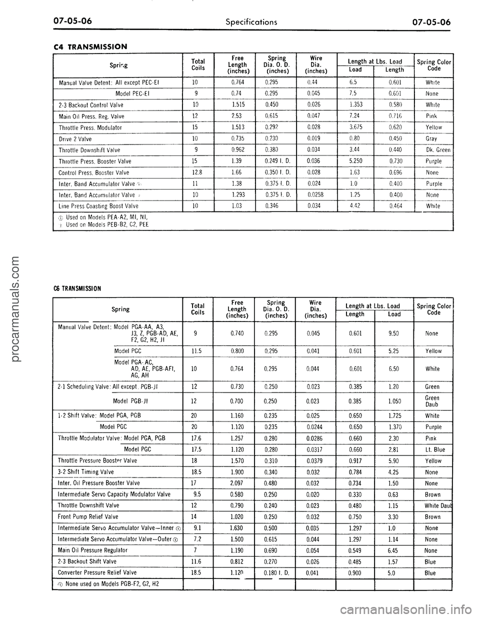
C4 TRANSMISSION
Spring
Manual Valve Detent: All except PEC-EI
Model PEC-EI
2-3 Backout Control Valve
Main Oil Press. Reg. Valve
Throttle Press. Modulator
Drive 2 Valve
Throttle Downshift Valve
Throttle Press. Booster Valve
Control Press. Booster Valve
Inter.
Band Accumulator Valve
.T,
Inter.
Band Accumulator Valve i
Line Press Coasting Boost Valve
Total
Coils
10
9
10
12
15
10
9
15
12.8
11
10
10
Free
Length
(inches)
0.764
0.74
1.515
2.53
1.513
0.735
0.962
1.39
1.66
1.38
1.293
1.03
Spring
Dia.
0. D.
(inches)
0.295
0.295
0.450
0.615
0.292
0.230
0.380
0.249
1. D.
0.350
1. D.
0.375
1. D.
0.375
1. D.
0.346
Wire
Dia.
(inches)
0.44
0.045
0.026
0.047
0.028
0.019
0.034
0.036
0.028
0.024
0.0258
0.034
Length
at Lbs.
Load
Load
6.5
7.5
1.353
7.24
3.675
0.80
3.44
5.250
1.63
1.0
1.25
4.42
Length
0.601
0.601
0.580
0.716
0.620
0.450
0.440
0.730
0.696
0.400
0.400
0.464
Spring Color
Code
White
None
White
Pink
Yellow
Gray
Dk. Green
Purple
None
Purple
None
White
® Used on Models PEA-A2, Ml, Nl,
'i.
Used on Models PEB-B2, C2, PEE
C6 TRANSMISSION
Spring
Manual Valve Detent: Model PGA-AA, A3,
J3,
Z, PGB-AD, AE,
F2, G2, H2,
Jl
Model PGC
Model PGA-AC,
AD,
AE, PGB-AFI,
AG,
AH
2-1 Scheduling Valve: All except, PGB-JI
Model PGB-JI
1-2 Shift Valve: Model PGA, PGB
Model PGC
Throttle Modulator Valve: Model PGA, PGB
Model PGC
Throttle Pressure Booster Valve
3-2 Shift Timing Valve
Inter.
Oil Pressure Booster Valve
Intermediate Servo Capacity Modulator Valve
Throttle Downshift Valve
Front Pump Relief Valve
Intermediate Servo Accumulator Valve—Inner ®
Intermediate Servo Accumulator Valve—Outer ©
Main Oil Pressure Regulator
2-3 Backout Shift Valve
Converter Pressure Relief Valve
cxy
None used on Models PGB-F2, G2, H2
Total
Coils
9
11.5
10
12
12
20
20
17.6
17.5
18
18.5
17
9.5
12
14
9.1
7.2
7
11.6
18.5
Free
Length
(inches)
0.740
0.800
0.764
0.730
0.700
1.160
1.120
1.257
1.120
1.570
1.900
2.097
0.580
0.790
1.020
1.630
1.500
1.190
0.812
1.120
Spring
Dia.
O. D.
(inches)
0.295
0.295
0.295
0.250
0.250
0.235
0.235
0.280
0.280
0.310
0.340
0.480
0.250
0.240
0.250
0.500
0.615
0.690
0.270
0.180
1.
D.
Wire
Dia.
(inches)
0.045
0.041
0.044
0.023
0.023
0.025
0.0244
0.0286
0.0317
0.0379
0.032
0.032
0.020
0.023
0.032
0.035
0.044
0.054
0.026
0.041
Length at Lbs. Load
Length
0.601
0.601
0.601
0.385
0.385
0.650
0.650
0.660
0.660
0.917
0.784
0.734
0.330
0.480
0.750
1.297
1.297
0.549
0.485
0.900
Load
9.50
5.25
6.50
1.20
1.050
1.725
1.370
2.30
2.81
5.90
4.25
1.50
0.63
1.15
3.30
1.0
1.14
6.45
1.57
5.0
Spring Color
Code
None
Yellow
White
Green
Green
Daub
White
Purple
Pink
Lt. Blue
Yellow
None
None
Brown
White Daul
Brown
None
None
None
Blue
Blueprocarmanuals.com