1969 FORD MUSTANG ground clearance
[x] Cancel search: ground clearancePage 58 of 413

02-02-39
Brake System
02-02-39
MAJOR REPAIR OPERATIONS
BRAKE DRUM REFINISHING
Minor scores on a brake drum can
be removed with sandpaper. A drum
that is excessively scored or shows a
total indicator runout of over 0.007
inch should be turned down. Remove
only enough stock to eliminate the
scores and true up the drum. The refi-
nished diameter must not exceed 0.060
inch oversize.
Check the inside diameter of the
brake drum with a brake drum mi-
crometer (Tool FRE-14^1).
If the drum diameter is less than
0.030 inch oversize after refinishing^
standard lining may be installed. If
the drum diameter is 0.030—0.060
inch oversize after refinishing, oversize
lining must be installed.
After a drum is turned down, wipe
the refinished surface with a cloth
soaked in clean denatured alcohol. If
one drum is turned down, the opposite
drum on the same axle should also be
cut down to the same size.
ROTOR REFINISHING
Rotunda Disc Brake Attachment,
FRE-2249-2, is the only recommended
tool to refinish the disc brake rotors.
The step-by-step resurfacing procedure
provided with the tool must be ad-
hered to.
The finished braking surfaces of the
rotor must be flat and parallel within
0.0007 inch; lateral runout must not
exceed 0.003 inch total indicator read-
ing, and the surface finish of the brak-
ing surfaces are to be 80/15 micro
inches. The minimum limiting dimen-
sions (Figs. 11 and 12, Part 2-1) from
the inboard bearing cup to the out-
board rotor face and from the inboard
bearing cup to the inboard rotor face
must be observed when removing ma-
terial from the rotor braking surfaces.
On all models except Lincoln Con-
tinental, the limiting dimensions are to
be measured with a ball and gage bar
(Rotunda Kit FRE-70160).
BRAKE SHOE RELINING
Brake linings that are worn to with-
in 1/32 inch of the rivet head or are
less than 0.030 inch thick (bonded lin-
ing) or have been contaminated with
brake fluid, grease or oil must be re-
placed. Failure to replace worn linings
will result in a scored drum. When it
is necessary to replace linings, they
must also be replaced on the wheel on
the opposite side of the vehicle.
Inspect brake shoes for distortion,
cracks, or looseness. If this condition
exists,
the shoe must be discarded. Do
not attempt to repair a defective brake
shoe.
1.
Wash the brake shoes thoroughly
in a clean solvent. Remove all burrs
or rough spots from the shoes.
2.
Check the inside diameter of the
brake drum with a brake drum mi-
crometer (tool FRE-1431). If the di-
ameter is less than 0.030 inches over-
size,
standard lining may be installed.
If the diameter is 0.030—0.060 inches
oversize, oversize lining should be in-
stalled.
3.
Position the new lining on the
shoe.
Starting in the center, insert and
secure the rivets, working alternately
towards each end. Replacement lin-
ings are ground and no further grind-
ing is required.
4.
Check the clearance between the
shoe and lining. The lining must seat
tightly against the shoe with not more
than 0.008 inch clearance between any
two rivets.
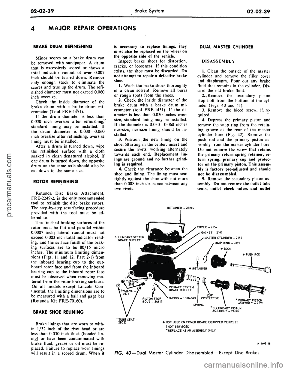
RETAINER - 2B245
DUAL MASTER CYLINDER
DISASSEMBLY
1.
Clean the outside of the master
cylinder and remove the filler cover
and diaphragm. Pour out any brake
fluid that remains in the cylinder. Dis-
card the old brake fluid.
2.*
Remove the secondary piston
stop bolt from the bottom of the cyl-
inder (Figs. 40 and 41).
3.
Remove the bleed screw, iL re-
quired.
4.
Depress the primary piston and
remove the snap ring from the retain-
ing groove at the rear of the master
cylinder bore (Fig. 42). Remove the
push rod and the primary piston as-
sembly from the master cylinder bore.
Do not remove the screw that retains
the primary return spring retainer, re-
turn spring, primary cup and protec-
tor on the primary piston. This assem-
bly is factory pre-adjusted and should
not be disassembled.
5.
Remove the secondary piston as-
sembly. Do not remove the outlet tube
seats,
outlet check valves and outlet
SECONDARY SYSTEM
BRAKE OUTLET
COVER -2166
GASKET-2167
MASTER CYLINDER -2155
SNAP RING -7821
BOOT
PUSH ROD
PRIMARY PISTON
ASSEMBLY - 2169
tTUBE SEAT-
2B220
* SECONDARY PISTON
ASSEMBLY - 2A502
• NOT USED ON POWER BRAKE EQUIPPED VEHICLES
fNOT SERVICED
•REPLACE AS AN ASSEMBLY ONLY
H 1499-B
FIG. 40— Dual Master Cylinder Disassembled—Except Disc Brakesprocarmanuals.com
Page 120 of 413

03-05-07
Steering Columns And Linkage
03-05-07
the steering column
(F in Fig. 8).
7.
Disconnect
the
transmission shift
rod
at the
shift tube.
8. Working under
the
hood, install
the aligning spacer (Fig.
9)
around
the
visible portion
of the
steering shaft
and slide
it up the
shaft into
the
steer-
ing column.
It may be
necessary
to
move
the
shaft back
and
forth
to
com-
pletely install
the
spacer.
9.
At
this point
the
steering column
assembly, being loose,
may
have
dropped toward
the
steering gear
grounding
the
steering shaft
on the
steering gear input shaft.
To
properly
establish
the
steering shaft
to
steering
gear clearance, insert
a 1/8
diameter
rod
or
drill through
the
opening
in the
upper half
of the
flex coupling.
10.
Tighten
to a
snug
fit
(approxi-
mately
2-3
ft-lb)
the
nuts retaining
the
toe plates
to the
dash panel
(B in Fig.
8).
11.
If the
aligning spacer cannot
be
rotated freely,
the
dash panel holes
must
be
filed
or
reamed
for
greater
travel
(as
mentioned
in the
second
paragraph
at the
beginning
of
this
procedure).
12.
Tighten
all
nuts
and
bolts
(noted
as C, D and E in
Fig.
8) in the
passenger compartment
to a
snug
fit
(approximately 2-3 ft-lb). Again check
aligning spacer
for
looseness. Perform
these tightening operations
in
alpha-
betical order.
13.
Tighten
the
lateral adjustment
bolt
(F in Fig. 8) to
snug
fit.
Again
check
the
aligning spacer
for
loose-
ness.
14.
Tighten
all
bolts and nuts
to the
proper torque value (listed
in Fig. 8)
in alphabetical order.
15.
Remove
the
steering shaft
al-
igning spacer.
16.
Remove
the 1/8
diameter
rod or
drill previously inserted
in the
flex
coupling.
17.
Reinstall
the
trim
at the
instru-
ment panel
to
steering column mount-
ing.
LINCOLN CONTINENTAL
If
a
condition
of
high shift
or
steer-
ing effort
is
experienced
it may be
caused
by
improper alignment
of the
energy absorbing steering column.
The
following procedures outline
the
steps
necessary
to
correctly realign either
fixed
or
tilt columns:
1.
Disconnect
the
battery.
2.
Loosen four
toe
plate attaching
nuts (Fig.
10).
3.
Loosen
one toe
plate
to
steering
column clamp bolt
and nut.
Check
alignment
of
steering shaft
to
shift
-HANDLE PORTION
2-3/4"
-*- 3/4"
BEND AROUND
STEERING SHAFT
DIMENSION
A:
STANDARD COLUMN 7/16"
TILT WHEEL COLUMN
1-1/8"
•2-3/4
FABRICATE ALIGNING SPACER OUT OF
PLASTIC SHIPPING COLLAR PROVIDED
ON SERVICE DRIVESHAFTS, OR OUT
OF
1/32"—1/16" CARDBOARD
STEERING SHAFT
ALIGNMENT SPACER-BEND AROUND
STEERING SHAFT (DIMENSION
A)
AND
SLIDE UP THE SHAFT INTO COLUMN
G1537-A
FIG. 9—Aligning Spacer Fabrication
and
Insertion
BRAKE PEDAL
SUPPORT BRACKET
PART
A-TOE PLATE
B-CLAMP
C-C0LUMN BRACKET
D-BRAKE PEDAL
SUPPORT BRACKET
TORQUE VALUE
8-12 FT. LB.
3-5 FT. LB.
10-15
FT.
LB.
8-12 FT. LB.
G1541-A
FIG. 10—Steering Column Alignment Locations
and
Torque
Specifications—Lincoln Continentalprocarmanuals.com
Page 219 of 413

04-02-22
Rear Axle — Removable Carrier Type
04-02-22
Too/-T59L-4204-A
or
44211
and
44211-A
EH92-C
FIG. 56—Checking Differential
Torque
High Torque
a. Insufficient lubricant on the
clutch plates.
b.
A clutch plate wedged in be-
tween the case halves.
c. An improperly centered Belleville
spring.
Low Torque
a. Weak Belleville spring.
b.
Improper amount of clutch
plates installed.
Under no circumstances should the
Belleville spring be ground down to
reduce torque. The torque required to
keep the side gear turning with new
clutch plates is 155 to 195 ft-lbs. On
reused clutch plates, the torque re-
quired is 75 ft-lbs minimun.
7.
If the differential bearings have
been removed, press them on as
shown in Figs. 49 and 50.
8. Install the side bearings on the
differential case, and install the case
in the carrier as described in steps 7
through 16 under Assembly and In-
stallation of Conventional Differential
Case. Adjust and check backlash be-
tween the ring gear and pinion as di-
rected under Differential Bearing Pre-
load Adjustments.
ASSEMBLY OF
TRACTION-LOK
DIFFERENTIAL CASE
1.
Lubricate all parts with Ford
Hypoid Lubricant (Ford Part No.
C6AZ-19580-C), during assembly of
differential.
2.
Mount the differential case in a
soft jawed vise and place a side gear
thrust washer and side gear in the
counterbore of the case.
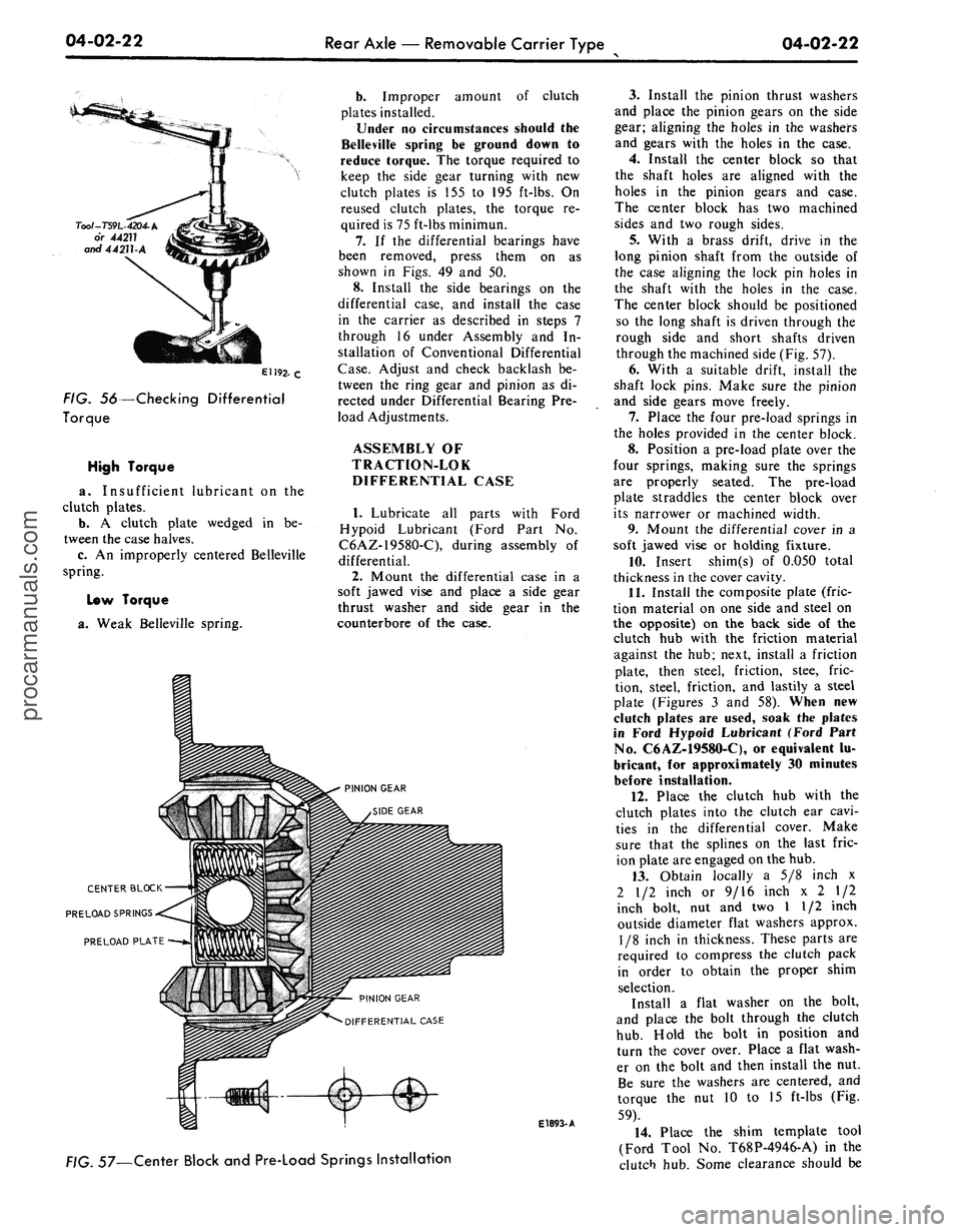
CENTER BLOCK
PRELOAD SPRINGS
PRELOAD PLATE
PINION GEAR
DIFFERENTIAL CASE
E1893-
A
. 57—Center Block and Pre-Load Springs Installation
3.
Install the pinion thrust washers
and place the pinion gears on the side
gear; aligning the holes in the washers
and gears with the holes in the case.
4.
Install the center block so that
the shaft holes are aligned with the
holes in the pinion gears and case.
The center block has two machined
sides and two rough sides.
5.
With a brass drift, drive in the
long pinion shaft from the outside of
the case aligning the lock pin holes in
the shaft with the holes in the case.
The center block should be positioned
so the long shaft is driven through the
rough side and short shafts driven
through the machined side (Fig. 57).
6. With a suitable drift, install the
shaft lock pins. Make sure the pinion
and side gears move freely.
7.
Place the four pre-load springs in
the holes provided in the center block.
8. Position a pre-load plate over the
four springs, making sure the springs
are properly seated. The pre-load
plate straddles the center block over
its narrower or machined width.
9. Mount the differential cover in a
soft jawed vise or holding fixture.
10.
Insert shim(s) of 0.050 total
thickness in the cover cavity.
11.
Install the composite plate (fric-
tion material on one side and steel on
the opposite) on the back side of the
clutch hub with the friction material
against the hub; next, install a friction
plate, then steel, friction, stee, fric-
tion, steel, friction, and lastily a steel
plate (Figures 3 and 58). When new
clutch plates are used, soak the plates
in Ford Hypoid Lubricant (Ford Part
No.
C6AZ-19580-C), or equivalent lu-
bricant, for approximately 30 minutes
before installation.
12.
Place the clutch hub with the
clutch plates into the clutch ear cavi-
ties in the differential cover. Make
sure that the splines on the last fric-
ion plate are engaged on the hub.
13.
Obtain locally a 5/8 inch x
2 1/2 inch or 9/16 inch x 2 1/2
inch bolt, nut and two I 1/2 inch
outside diameter flat washers approx.
1/8 inch in thickness. These parts are
required to compress the clutch pack
in order to obtain the proper shim
selection.
Install a flat washer on the bolt,
and place the bolt through the clutch
hub.
Hold the bolt in position and
turn the cover over. Place a flat wash-
er on the bolt and then install the nut.
Be sure the washers are centered, and
torque the nut 10 to 15 ft-lbs (Fig.
59).
14.
Place the shim template tool
(Ford Tool No. T68P-4946-A) in the
clutch hub. Some clearance should beprocarmanuals.com