1969 FORD MUSTANG turn signal
[x] Cancel search: turn signalPage 115 of 413
03-05-02
Steering Columns
And
Linkage
03-05-02
which also will shear away during
im-
pact.
TILT STEERING COLUMNS
The steering column
is of the col-
lapsible type
to
lessen
the
possibility
of injury
to the
driver
of the
vehicle
should
he
become involved
in an
acci-
dent.
The
lower
end of the
steering
column tube
at the
bellows area will
collapse approximately
six
inches
upon
a
hard impact.
The shift tube
and the
steering shaft
are provided with plastic dowels
and
will shear
and
allow them
to
collapse
in proportion
to the
outer tube upon
impact.
Once
the
steering column
has
been
collapsed,
a
complete
new
column
must
be
installed.
The tilt column features nine driv-
ing positions (four
up and
four down
from
a
center position).
The
.column
also features
a
turn signal switch with
a lane-changer position turn indicating
position
and
emergency warning flash-
er control.
TILT-AWAY STEERING COLUMNS
The tilt-away steering column
fea-
tures nine driving positions (four
up
and four down from
a
center position)
and
a
tilt-away position that
is
auto-
matically accomplished
on
Mustang
and Cougar models when
the
ignition
key
is
turned
to the
OFF
position
and
the left door
is
opened.
On
Thunder-
bird models,
the
tilt-away occurs when
the shift lever
is
placed
in
PARK
and
the driverns door
is
opened.
The steering column
is of the col-
lapsible type
to
lessen
the
possibility
of injury
to the
driver
of the
vehicle
should
he
become involved
in an
acci-
dent.
The
lower
end of the
steering
column tube
at the
bellows area will
collapse approximately
six
inches
upon
a
hard impact.
The shift tube
and the
steering shaft
are provided with plastic dowels
and
will shear
and
allow them
to
collapse
in proportion
to the
outer tube upon
impact.
Once
the
steering column
has
been
collapsed,
a
complete
new
column
must
be
installed along with mounting
brackets which will also shear away
during impact.
IN-VEHICLE ADJUSTMENTS
AND
REPAIRS
STEERING WHEEL SPOKE
POSITION ADJUSTMENT
When
the
steering gear
is on the
high point,
the
front wheels should
be
in
the
straight-ahead position
and the
steering wheel spokes should
be in
their normal position with
the
Pitman
arm pointing directly forward.
If the
spokes
are not in
their normal posi-
tion, they
can be
adjusted without
dis-
turbing
the
toe-in adjustment (Part
3-1).
STEERING WHEEL
REPLACEMENT
1.
Disconnect
the
negative cable
from
the
battery.
2.
Working from
the
underside
of
the steering wheel spoke, remove
the
crash
pad
attaching screws. Lift
the
crash
pad
from
the
wheel.
(On
Conti-
nental Mark
III
models,
pry out the
crash
pad
insert
and
remove
the two
screws that secure
the
crash
pad. Re-
move
the
crash
pad. On
models
equipped with steering wheel mounted
speed controls, refer
to
Group
16 for
removal instructions). Remove
the
horn ring
(if so
equipped)
by
turning
it counterclockwise.
3.
Remove
the
steering wheel
nut,
and then remove
the
steering wheel
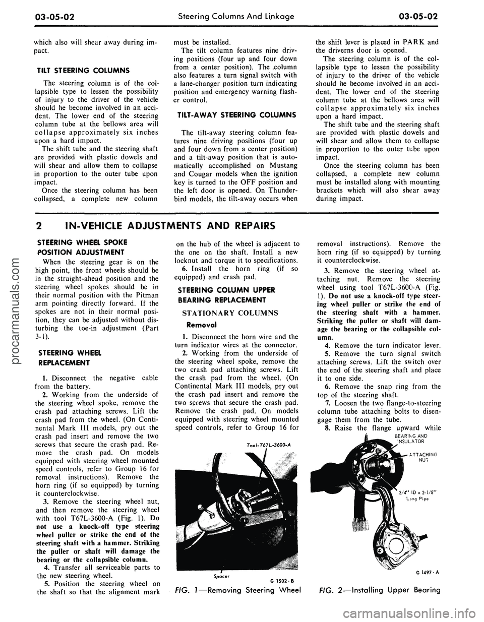
with tool T67L-3600-A
(Fig. 1). Do
not
use a
knock-off type steering
wheel puller
or
strike
the end of the
steering shaft with
a
hammer. Striking
the puller
or
shaft will damage
the
bearing
or the
collapsible column.
4.
Transfer
all
serviceable parts
to
the
new
steering wheel.
5.
Position
the
steering wheel
on
the shaft
so
that
the
alignment mark
on
the hub of the
wheel
is
adjacent
to
the
one on the
shaft. Install
a new
locknut
and
torque
it to
specifications.
6. Install
the
horn ring
(if so
equipped)
and
crash
pad.
STEERING COLUMN UPPER
BEARING REPLACEMENT
STATIONARY COLUMNS
Removal
1. Disconnect
the
horn wire
and the
turn indicator wires
at the
connector.
2.
Working from
the
underside
of
the steering wheel spoke, remove
the
two crash
pad
attaching screws. Lift
the crash
pad
from
the
wheel.
(On
Continental Mark
III
models,
pry out
the crash
pad
insert
and
remove
the
two screws that secure
the
crash
pad.
Remove
the
crash
pad. On
models
equipped with steering wheel mounted
speed controls, refer
to
Group
16 for
7oo/-T67L-3600-A
removal instructions). Remove
the
horn ring
(if so
equipped)
by
turning
it counterclockwise.
3.
Remove
the
steering wheel
at-
taching
nut.
Remove
the
steering
wheel using tool T67L-3600-A
(Fig.
1).
Do not use a
knock-off type steer-
ing wheel puller
or
strike
the end of
the steering shaft with
a
hammer.
Striking
the
puller
or
shaft will
dam-
age
the
bearing
or the
collapsible
col-
umn.
4.
Remove
the
turn indicator lever.
5.
Remove
the
turn signal switch
attaching screws. Lift
the
switch over
the
end of the
steering shaft
and
place
it
to one
side.
6. Remove
the
snap ring from
the
top
of the
steering shaft.
7.
Loosen
the two
flange-to-steering
column tube attaching bolts
to
disen-
gage them from
the
tube.
8. Raise
the
flange upward while
BEARING
AND
INSULATOR
Spacer
G 1502 -B
FIG.
1—Removing
Steering Wheel
G 1497-A
FIG. 2—Installing Upper Bearingprocarmanuals.com
Page 116 of 413
03-05-03
Steering Columns And Linkage
03-05-03
tapping the steering shaft lightly with
a plastic hammer to free the bearing
and flange from the shaft.
9. Remove the bearing and insula-
tor from the flange.
Installation
1.
Install flange bolts (square head)
in flange if they were removed. Turn
the nuts onto the bolts one complete
turn only.
2.
Position the flange onto the
steering column tube.
3.
Engage the two flange bolt heads
with the square holes in the column
tube,
then tighten the two attaching
nuts to specification.
4.
Position the bearing and insula-
tor on the shaft. Work it down onto
the shaft as far as possible, then place
a piece of 3/4 ID x 2 1/8 inch pipe
over the end of the shaft and install
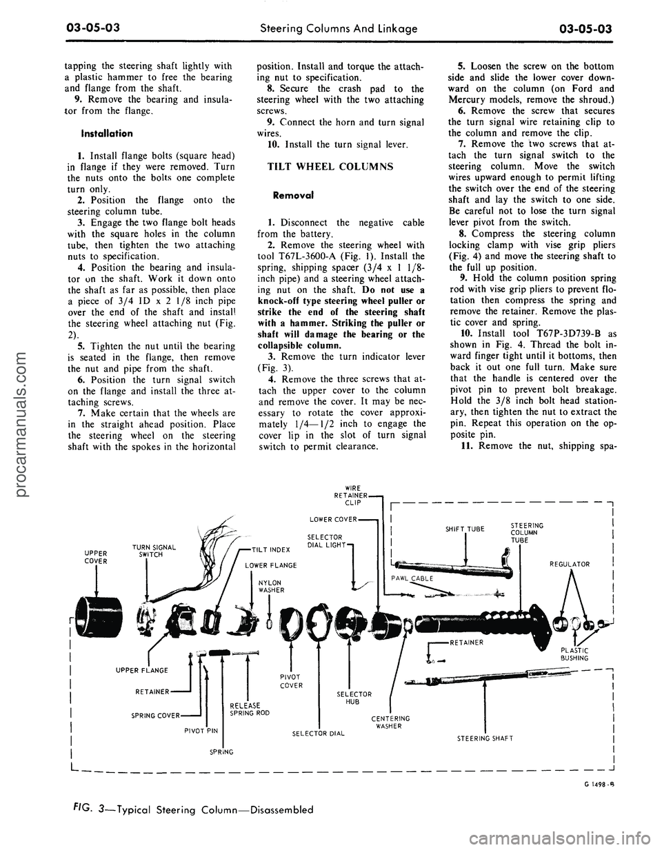
the steering wheel attaching nut (Fig.
2).
5.
Tighten the nut until the bearing
is seated in the flange, then remove
the nut and pipe from the shaft.
6. Position the turn signal switch
on the flange and install the three at-
taching screws.
7.
Make certain that the wheels are
in the straight ahead position. Place
the steering wheel on the steering
shaft with the spokes in the horizontal
position. Install and torque the attach-
ing nut to specification.
8. Secure the crash pad to the
steering wheel with the two attaching
screws.
9. Connect the horn and turn signal
wires.
10.
Install the turn signal lever.
TILT WHEEL COLUMNS
Removal
1.
Disconnect the negative cable
from the battery.
2.
Remove the steering wheel with
tool T67L-3600-A (Fig. 1). Install the
spring, shipping spacer (3/4 x 1 1/8-
inch pipe) and a steering wheel attach-
ing nut on the shaft. Do not use a
knock-off type steering wheel puller or
strike the end of the steering shaft
with a hammer. Striking the puller or
shaft will damage the bearing or the
collapsible column.
3.
Remove the turn indicator lever
(Fig. 3).
4.
Remove the three screws that at-
tach the upper cover to the column
and remove the cover. It may be nec-
essary to rotate the cover approxi-
mately
1/4—1/2
inch to engage the
cover lip in the slot of turn signal
switch to permit clearance.
5.
Loosen the screw on the bottom
side and slide the lower cover down-
ward on the column (on Ford and
Mercury models, remove the shroud.)
6. Remove the screw that secures
the turn signal wire retaining clip to
the column and remove the clip.
7.
Remove the two screws that at-
tach the turn signal switch to the
steering column. Move the switch
wires upward enough to permit lifting
the switch over the end of the steering
shaft and lay the switch to one side.
Be careful not to lose the turn signal
lever pivot from the switch.
8. Compress the steering column
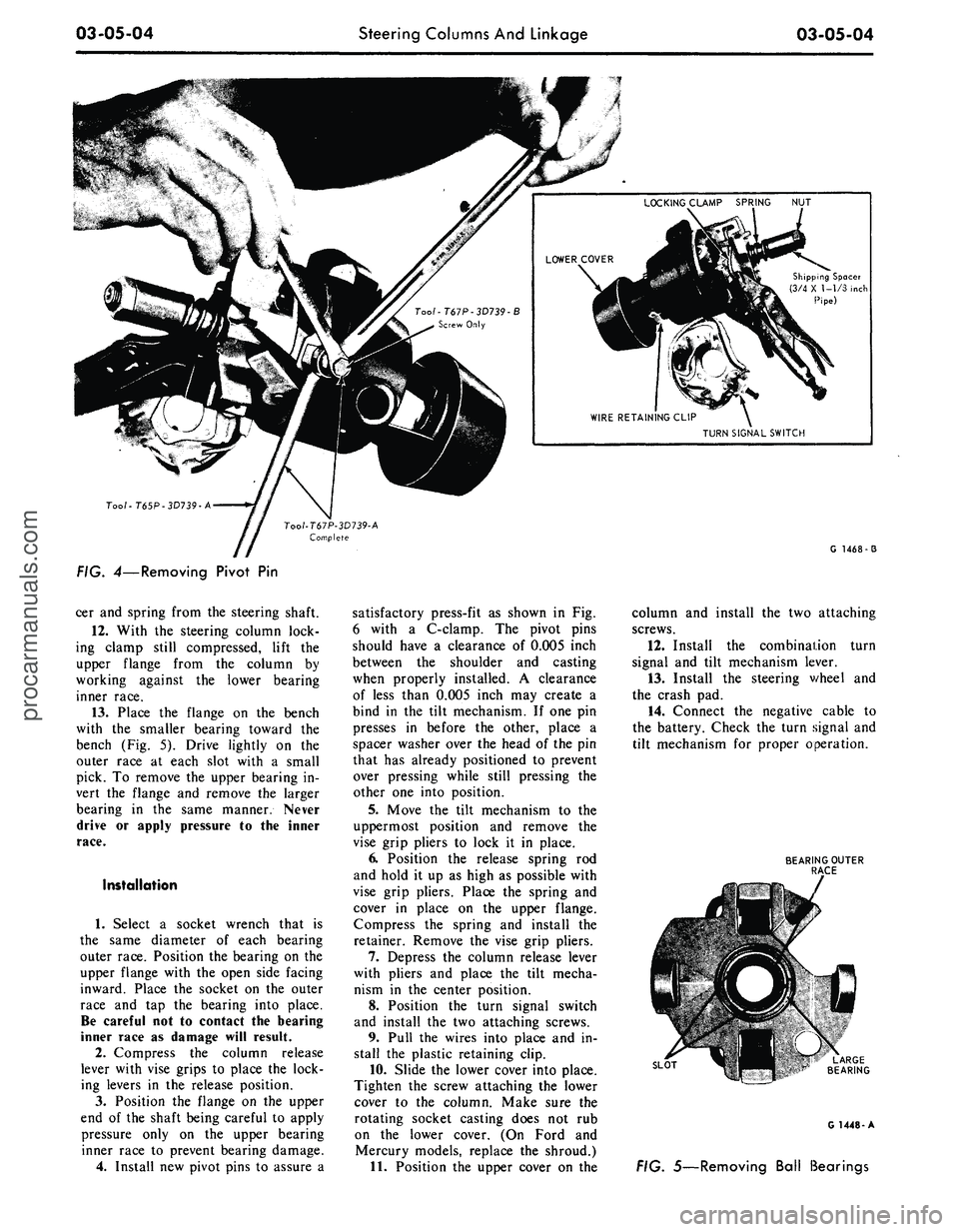
locking clamp with vise grip pliers
(Fig. 4) and move the steering shaft to
the full up position.
9. Hold the column position spring
rod with vise grip pliers to prevent flo-
tation then compress the spring and
remove the retainer. Remove the plas-
tic cover and spring.
10.
Install tool T67P-3D739-B as
shown in Fig. 4. Thread the bolt in-
ward finger tight until it bottoms, then
back it out one full turn. Make sure
that the handle is centered over the
pivot pin to prevent bolt breakage.
Hold the 3/8 inch bolt head station-
ary, then tighten the nut to extract the
pin. Repeat this operation on the op-
posite pin.
11.
Remove the nut, shipping spa-
UPPER
COVER
J
G 1498-B
FIG. 3—Typical Steering Column—Disassembledprocarmanuals.com
Page 117 of 413
03-05-04
Steering Columns And Linkage
03-05-04
Shipping Spacer
(3/4 X 1-1/3 inch
Pipe)
TURN SIGNAL SWITCH
Too/-T65P-3D739-A
G 1468-3
FIG. 4—Removing Pivot
Pin
cer and spring from the steering shaft.
12.
With
the
steering column lock-
ing clamp still compressed, lift
the
upper flange from
the
column
by
working against
the
lower bearing
inner race.
13.
Place
the
flange
on the
bench
with
the
smaller bearing toward
the
bench (Fig.
5).
Drive lightly
on the
outer race
at
each slot with
a
small
pick.
To
remove the upper bearing in-
vert
the
flange
and
remove
the
larger
bearing
in the
same manner. Never
drive
or
apply pressure
to the
inner
race.
Installation
1.
Select
a
socket wrench that
is
the same diameter
of
each bearing
outer race. Position the bearing on the
upper flange with the open side facing
inward. Place
the
socket
on the
outer
race
and tap the
bearing into place.
Be careful not
to
contact
the
bearing
inner race
as
damage will result.
2.
Compress
the
column release
lever with vise grips
to
place the lock-
ing levers
in the
release position.
3.
Position
the
flange
on the
upper
end
of
the shaft being careful
to
apply
pressure only
on the
upper bearing
inner race
to
prevent bearing damage.
4.
Install new pivot pins
to
assure
a
satisfactory press-fit
as
shown
in Fig.
6 with
a
C-clamp.
The
pivot pins
should have
a
clearance
of
0.005 inch
between
the
shoulder
and
casting
when properly installed.
A
clearance
of less than 0.005 inch may create
a
bind
in the
tilt mechanism.
If
one pin
presses
in
before
the
other, place
a
spacer washer over the head
of
the pin
that has already positioned
to
prevent
over pressing while still pressing
the
other one into position.
5.
Move
the
tilt mechanism
to the
uppermost position
and
remove
the
vise grip pliers
to
lock
it in
place.
6. Position
the
release spring
rod
and hold
it
up
as
high
as
possible with
vise grip pliers. Place
the
spring
and
cover
in
place
on the
upper flange.
Compress
the
spring
and
install
the
retainer. Remove the vise grip pliers.
7.
Depress
the
column release lever
with pliers
and
place
the
tilt mecha-
nism
in the
center position.
8. Position
the
turn signal switch
and install
the
two attaching screws.
9. Pull
the
wires into place and
in-
stall
the
plastic retaining clip.
10.
Slide the lower cover into place.
Tighten
the
screw attaching the lower
cover
to the
column. Make sure
the
rotating socket casting does
not rub
on
the
lower cover.
(On
Ford
and
Mercury models, replace
the
shroud.)
11.
Position the upper cover
on the
column
and
install
the
two attaching
screws.
12.
Install
the
combination turn
signal
and
tilt mechanism lever.
13.
Install
the
steering v/heel
and
the crash pad.
14.
Connect
the
negative cable
to
the battery. Check the turn signal and
tilt mechanism
for
proper operation.
BEARING OUTER
RACE
SLOT
G 1448-A
FIG. 5—Removing Ball Bearingsprocarmanuals.com
Page 121 of 413

03-05-08
Steering Columns And Linkage
03-05-08
tube.
In some instances the column
will shift into proper alignment when
the toe plate attaching nuts are loos-
ened. (Alignment is acceptable if a
.010 inch feeler blade can be passed
freely, completely around the area be-
tween the outer diameter of the steer-
ing shaft and the shift tube.) if the
misalignment condition can be attrib-
uted to this area, file or ream the dash
panel holes for greater clearance. If
the alignment is maintained after the
toe plate nuts and toe plate to column
clamp bolt and nut are torqued to the
8-12 ft-lb specification, no further ad-
justment is necessary.
4.
Remove instrument panel lower
trim panel. Vehicles equipped with a
combination radio stereo tape player
will require removal of the radio and
tape player assembly in order to gain
access to the upper R.H. steering col-
umn support bracket bolt.
5.
Loosen the seven bolts at the
steering column support bracket and
brake pedal support bracket.
6. Install a 3/16 inch diameter rod
spacer in the flex coupling to assure
proper clearance between upper and
lower steering shaft.
7.
Raise the vehicle, remove the
transmission splash shield, and visual-
ly align the column to center the
steering shaft in the column. Tighten
two toe plate attaching nuts sufficient-
ly to hold the column alignment (two
persons may be required for this oper-
ation).
8. Lower the vehicle.
9. Check the clearance between the
steering column support bracket and
the instrument panel bracket. It may
be necessary to add shims (Part Num-
ber MK-3054-A .060 inch thick, or
C3AZ-3054-A, .113 inch thick) be-
tween the support bracket and the in-
strument panel bracket to prevent
movement of the column when the
support bracket bolts are tightened.
10.
Loosen the two toe plate at-
taching nuts previously tightened. Re-
check steering column alignment. In
some instances it may be necessary to
enlarge the holes in the dash panel in
order to obtain proper column align-
ment.
11.
With the column properly al-
igned, torque the four toe plate at-
taching nuts to 4-9 ft-lbs.
12.
Torque the toe plate to steering
column clamp bolt to 3-5 ft-lbs.
13.
Recheck steering shaft to shift
tube alignment. A 0.10 inch feeler
blade should pass freely, completely
around the area between the outer di-
ameter of the steering shaft and shift-
er tube.
14.
Raise the vehicle.
15.
Adjust transmission shift link-
age.
16.
Install transmission splash
shield.
17.
Lower the vehicle.
18.
Install the radio stereo tape
player if so equipped.
19.
Install instrument panel lower
trim panel.
20.
Connect the battery.
REMOVAL AND INSTALLATION
STEERING COLUMN
FORD, MERCURY, METEOR
Removal
1.
Disconnect the battery cable
from the negative post.
2.
Disconnect the turn signal switch
wires at the connector.
3.
Disconnect the neutral start
switch and back-up light switch wires
from the switches.
4.
Disconnect the transmission con-
trol rod(s) from the lever(s) at the
lower end of the column.
5.
Remove the bolt that secures the
flex coupling to the steering gear.
6. Remove the nuts that secure the
column retainer and seal at the toe
plate (Fig. 11).
7.
Ford, Meteor: Remove the two
screws that secure the lower trim
shroud to the upper trim shroud. Re-
move the two shrouds.
Mercury: Remove the two screws
that secure the lower trim shroud to
the upper trim shroud. Remove the
top shroud Disconnect the ignition
switch light bulb. Remove the ignition
and light switch bezels and spring clip
and remove the lower shroud. Discon-
nect the light switch electrical connec-
tor block.
8. Remove the two screws that se-
cure the intermediate bracket to the
column lower bracket.
9. While supporting the steering
column, remove the two nuts that se-
cure the column lower bracket to the
instrument panel. Remove the brack-
ets.
10.
Lift the steering column and
wheel from the vehicle.
Installation
1.
Position the steering column in
the vehicle. Index the block tooth on
the steering gear shaft with the corre-
sponding slot on the flex coupling. In-
stall and tighten the flex coupling-
to-steering gear attaching bolt.
2.
Place the column upper bracket
and column lower bracket in position
on the column and install but do not
tighten the four attaching nuts.
3.
Install and tighten the two nuts
that secure the column lower bracket
to the instrument panel. Make certain
the column is properly positioned rela-
tive to the flex coupling input shaft
connection.
4.
Install and tighten the screws
that secure the intermediate bracket to
the column lower bracket.
5.
Tighten the four attaching nuts
at the upper and lower brackets and
the two nuts at the upper bracket to
instrument panel. The dial pointer (if
so equipped) should be adjusted to
coincide with the selector lever.
6. Install and tighten the nuts and
bolts that secure the column retainer
and seal at the toe plate. Make sure
the steering shaft is centered in the
column before tightening the nuts.
7.
Ford, Meteor: Install and tighten
the two screws that secure the lower
trim shroud to the upper trim shroud.
Mercury: Connect the light switch
harness block. Install the ignition and
light switch bezels. Connect the igni-
tion switch light bulb. Install the top
shroud and the two screws that secure
the lower trim shroud to the upper
shroud.
8. Connect the transmission control
rod(s) to the lever(s) at the lower end
of the column.
9. Connect the neutral start switch
and back-up light switch to their re-
spective terminals.
10.
Connect the turn signal switch
wires.
11.
Connect the negative battery
cable to the battery.
12.
Check the operation of the
steering tilt mechanism if so equipped
and the switches.procarmanuals.com
Page 122 of 413
03-05-09
Steering Columns And Linkage
03-05-09
FAIRLANE, FALCON
AND MONTEGO
Removal
1.
Disconnect the battery cable
from the negative post.
2.
Disconnect the turn signal switch
wires at the connector.
3.
Disconnect the neutral start
siwtch (with automatic transmission)
and back-up light switch wires from
the switches.
4.
Disconnect the transmission con-
trol rod(s) from the lever(s) at the
lower end of the column.
5.
Remove the bolt that secures the
flex coupling to the steering gear (Fig.
12).
6. Remove the nuts and bolts that
secure the column retainer and seal at
the toe plate.
7.
Disconnect the nuts that secure
the column upper and lower brackets
to the brake pedal support bracket
and the dash panel.
8. Lift the column from the vehicle.
Installation
1.
Position the steering column in
the vehicle. Make sure that the wheels
are in the straight ahead position and
that the steering wheel spokes are in a
horizontal position when the flex cou-
pling engages the input shaft splines.
2.
Install but do not tighten the
nuts that secure the column upper and
lower brackets to the brake pedal sup-
port bracket and the dash panel.
Make certain the column is properly
positioned relative to the flex coupling
inpui shaft connection.
3.
Install and tighten the flex cou-
pling-to-steering gear attaching bolt.
4.
Tighten the nuts at the brake
pedal support bracket and the dash
panel.
5.
Install and tighten the nuts and
bolts that secure the column retainer
and seal at the toe plate.
6. Connect the transmission control
rod(s) to the lever(s) at the lower end
of the column.
7.
Connect the neutral start switch
(if so equipped) and back-up light
switch to their respective terminals.
8. Connect the turn signal switch
wires.
COLUMN UPPER \
BRACKET-3506 V
BRAKE PEDAL
SUPPORT BRACKET
TRIMSHROUD-3530
UPPER CLAMP-3507,
COLUMN LOWER
BRACKET-3R547
•
FLEXCOUPLING-3A525
^INTERMEDIATE
BRACKET-3676
VIEW AA
G1616-A
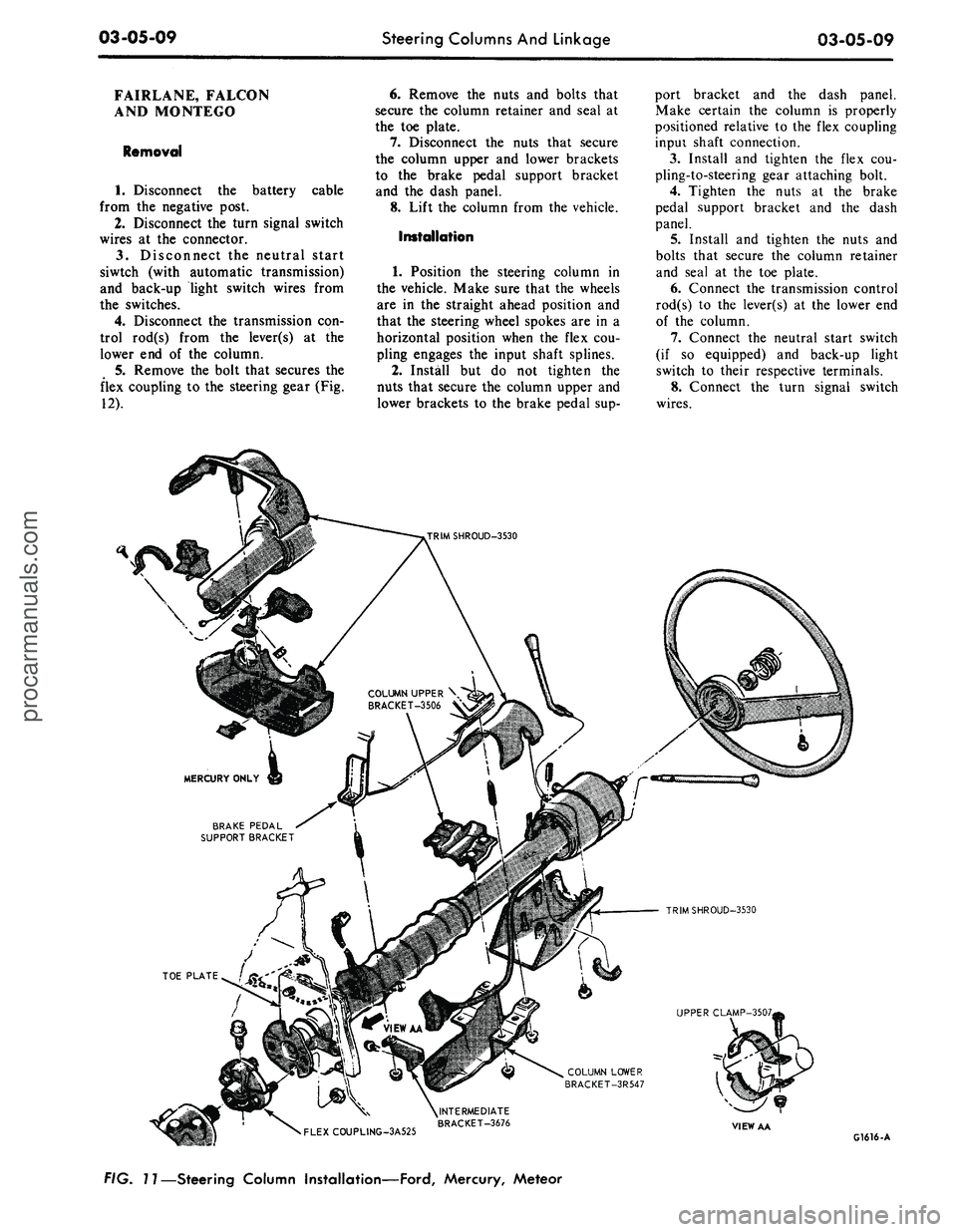
FIG. 11—Steering Column Installation—Ford, Mercury, Meteorprocarmanuals.com
Page 123 of 413
03-05-10
Steering Columns And Linkage
03-05-10
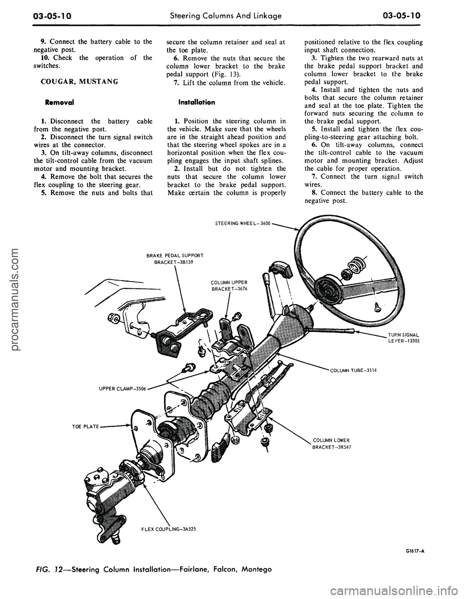
9. Connect the battery cable to the
negative post.
10.
Check the operation of the
switches.
COUGAR, MUSTANG
Removal
cable
1.
Disconnect the battery
from the negative post.
2.
Disconnect the turn signal switch
wires at the connector.
3.
On tilt-away columns, disconnect
the tilt-control cable from the vacuum
motor and mounting bracket.
4.
Remove the bolt that secures the
flex coupling to the steering gear.
5.
Remove the nuts and bolts that
secure the column retainer and seal at
the toe plate.
6. Remove the nuts that secure the
column lower bracket to the brake
pedal support (Fig. 13).
7.
Lift the column from the vehicle.
Installation
1.
Position the steering column in
the vehicle. Make sure that the wheels
are in the straight ahead position and
that the steering wheel spokes are in a
horizontal position when the flex cou-
pling engages the input shaft splines.
2.
Install but do not tighten the
nuts that secure the column lower
bracket to the brake pedal support.
Make certain the column is properly
positioned relative to the flex coupling
input shaft connection.
3.
Tighten the two rearward nuts at
the brake pedal support bracket and
column lower bracket to the brake
pedal support.
4.
Install and tighten the nuts and
bolts that secure the column retainer
and seal at the toe plate. Tighten the
forward nuts securing the column to
the brake pedal support.
5.
Install and tighten the flex cou-
pling-to-steering gear attaching bolt.
6. On tilt-away columns, connect
the tilt-control cable to the vacuum
motor and mounting bracket. Adjust
the cable for proper operation.
7.
Connect the turn signal switch
wires.
8. Connect the battery cable to the
negative post.
STEERING WHEEL-3600
BRAKE PEDAL SUPPORT
BRACKET-3B139
TOE PLATE
COLUMN LOWER
BRACKET-3R547
FLEXCOUPLING-3A525
G1617-A
FIG. 72—Steering Column Installation—Fairlane, Falcon, Montegoprocarmanuals.com
Page 124 of 413

03-05-11
Steering Columns
And
Linkage
03-05-11
9. Check
the
operation
of the
steer-
ing tilt mechanism
(if so
equipped)
and
the
switches.
THUNDERBIRD
AND
CONTINENTAL MARK
III
Removal
1.
Remove
the
instrument panel
lower outer finish panel, instrument
panel steering column plate
and
cover.
2.
Disconnect
the
negative cable
from
the
battery.
3.
Remove
the
bolt that attaches
the flexible coupling
to the
steering
shaft.
4.
Disconnect
the
shift
rod
from
the
lever
at the
lower
end of the
column.
5.
Remove
the
four screws that
at-
tach
the
column retainer
to the
dash
panel.
6. Working from
the
underside
of
the instrument panel disconnect
the
steering column tilt-control cable from
the vacuum motor
and
mounting
bracket
(if so
equipped)
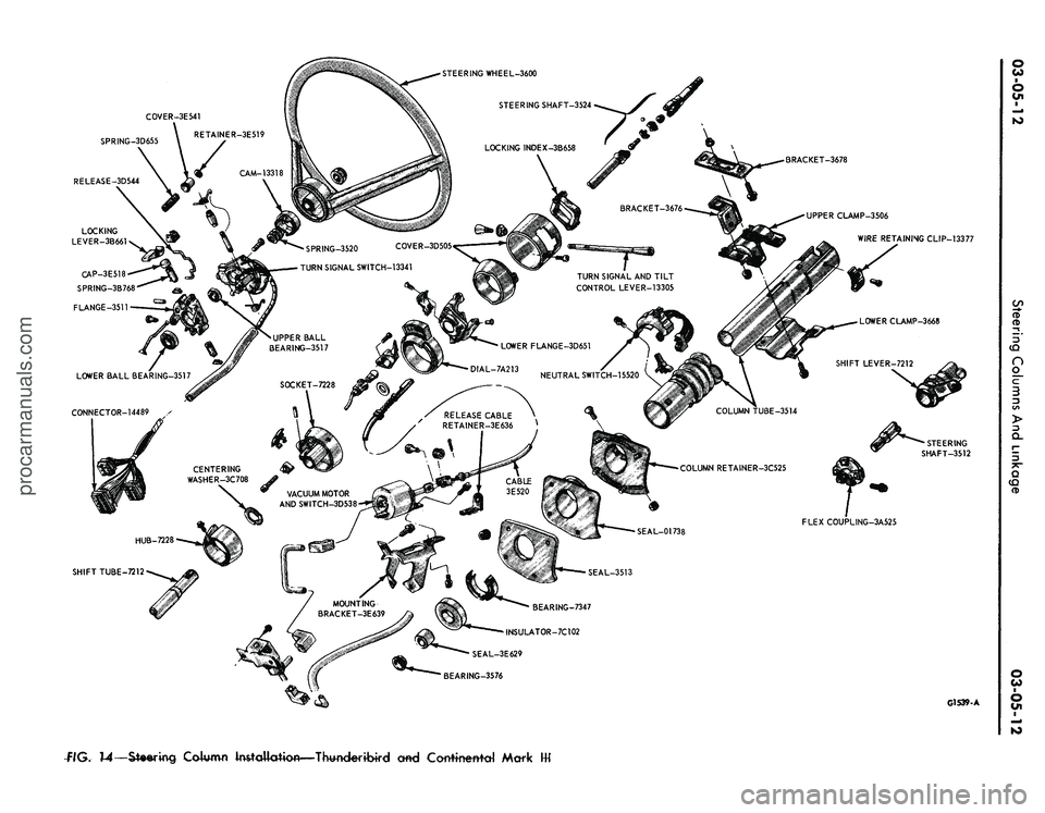
(Fig. 14).
7.
Disconnect
the
turn signal
switch,
and
emergency flasher wires
at
the connectors. Disconnect
the
wires
from
the
neutral start switch.
8. While supporting
the
steering
column, remove
the
four bolts that
at-
tach
the
lower clamp
to the
upper
clamp
(Fig. 14).
Lift
the
column from
the vehicle.
Installation
1.
Position
the
column
in the
vehi-
cle making sure that
the
steering shaft
engages
the
flex coupling.
1.
Install
the
column retainer-
to-dash panel attaching screws,
but do
not tighten them.
3.
Install
the
lower clamp
and the
attaching nuts. Tighten
the
nuts fing-
ertight.
4.
Move
the
lower flange
as re-
quired
to
center
the
steering shaft
in
the tube. Aligning procedures
are de-
tailed
in
Part
3-1.
Tighten
the
lower
flange attaching nuts when
the
shaft
is
centered.
5.
Connect
the
shift
rod to the
shift
lever
at the
lower
end of the
column.
6. Install
and
tighten
the
flex
cou-
pling attaching bolt.
7.
Tighten
the
instrument panel-
to-clamp attaching nuts.
BRAKE PEDAL SUPPORT
STEERING WHEEL-3600
TURN SIGNAL LEVER-13305
COLUMN TUBE-3514
COLUMN LOWER BRACKET-3R547
•TOE PLATE
FLEX COUPLING-3A525
G1618-A
f/G.
73—Steering Column Installation—Cougar, Mustangprocarmanuals.com
Page 125 of 413
SPRING-3D655
RELEASE-3D544
BRACKET-3678
UPPER CLAMP-3506
WIRE RETAINING CLIP-13377
SPRING-3520 COVER-3D505
TURN SIGNAL SWITCH-13341
TURN SIGNAL AND TILT
CONTROL LEVER-13305
FLEX COUPLING-3A525
BEARING-7347
INSULATOR-7C102
SEAL-3E629
BEARING-3576
G1539-A
flG.
14—Steering
Column Installation—Thwderibird cmd Corrttnettfd Markprocarmanuals.com