Page 25 of 390

KAPITEL 4
MOTOR
VERGASER ...............................................4-1
ZYLINDERKOPF .......................................4-8
NOCKENWELLE UND KIPPHEBEL .......4-13
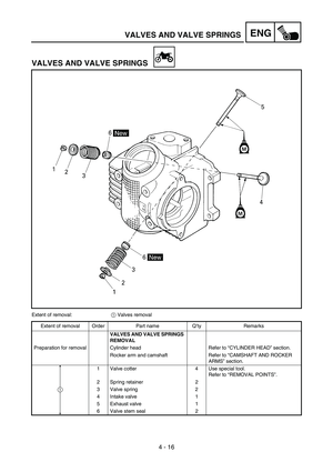
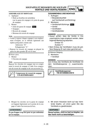
VENTILE UND VENTILFEDERN .............4-16
ZYLINDER UND KOLBEN ......................4-21
KUPPLUNG .............................................4-27
KICKHEBELWELLE ................................4-33
SCHALTWELLE ......................................4-34
ÖLPUMPE ................................................4-36
LICHTMASCHINE (TT-R90) ....................4-39
LICHTMASCHINE UND
STARTERKUPPLUNG (TT-R90E) ..........4-41
KURBELGEHÄUSE UND
KURBELWELLE ......................................4-45
SCHALTGABELN, SCHALTWALZE UND
GETRIEBE ...............................................4-48
KAPITEL 5
FAHRWERK
VORDER- UND HINTERRAD ....................5-1
TELESKOPGABEL .................................5-10
LENKER ...................................................5-13
LENKUNG ................................................5-18
SCHWINGE ..............................................5-20
KAPITEL 6
ELEKTRISCHE ANLAGE
ELEKTRISCHE BAUTEILE UND
SCHALTPLAN ...........................................6-1
ZÜNDSYSTEM ...........................................6-3
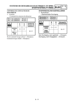
STARTSYSTEM (TT-R90E) .......................6-7
LADESYSTEM (TT-R90E) .......................6-15
VERGASERHEIZUNG .............................6-17
VERZEICHNIS DER
WARTUNGSARBEITEN ..........................6-21
CHAPITRE 4
MOTEUR
CARBURATEUR ............................................ 4-1
CULASSE ........................................................ 4-8
ARBRE A CAMES ET CULBUTEURS ..... 4-13
SOUPAPES ET RESSORTS DE
SOUPAPE ...................................................... 4-16
CYLINDRE ET PISTON ............................. 4-21
EMBRAYAGE .............................................. 4-27
ARBRE DE KICK ......................................... 4-33
AXE DE SELECTEUR ................................. 4-34
POMPE A HUILE ......................................... 4-36
VOLANT MAGNETIQUE CDI (TT-R90) ...4-39
VOLANT MAGNETIQUE CDI ET
EMBRAYAGE
DU DEMARREUR (TT-R90E) .................... 4-41
CARTER MOTEUR ET
VILEBREQUIN ............................................ 4-45
FOURCHETTE DE SELECTION,
TAMBOUR ET BOITE DE VITESSES ..... 4-48
CHAPITRE 5
CHASSIS
ROUE AVANT ET ROUE ARRIERE .......... 5-1
FOURCHE ..................................................... 5-10
GUIDON ........................................................ 5-13
DIRECTION .................................................. 5-18
BRAS OSCILLANT ...................................... 5-20
CHAPITRE 6
PARTIE ELECTRIQUE
COMPOSANTS ELECTRIQUES ET
SCHEMA DE CABLAGE .............................. 6-1
SYSTEME D’ALLUMAGE ........................... 6-3
SYSTEME DE DEMARRAGE
ELECTRIQUE (TT-R90E) ............................ 6-7
SYSTEME DE CHARGE (TT-R90E) ......... 6-15
SYSTEME DE RECHAUFFAGE DU
CARBURATEUR .......................................... 6-17
FICHE D’ENTRETIEN ............................... 6-21
Page 26 of 390
1 - 1
GEN
INFO
DESCRIPTION
EC100000
GENERAL INFORMATION
EC110000
DESCRIPTION
1“ENGINE STOP” switch
2Main switch (TT-R90E)
3Start switch (TT-R90E)
4Front brake lever
5Throttle grip
6Fuel tank cap
7Kick starter
8Fuel tank
9Air cleaner
0Rear brake pedal
AFuel cock
BStarter lever (choke)
CDrive chain
DShift pedal
EFront fork
NOTE:
The machine you have purchased may differ
slightly from those shown in the following.
Designs and specifications are subject to
change without notice.
The illustration shows the TT-R90E.
1
4
5
6
23
1
Page 27 of 390

GEN
INFO
ALLGEMEINES
FAHRZEUGBESCHREIBUNG
1Motorstoppschalter “ENGINE STOP”
2Zündschloss (TT-R90E)
3Starterschalter (TT-R90E)
4Handbremshebel
5Gasdrehgriff
6Tankverschluss
7Kickstarterhebel
8Kraftstofftank
9Luftfilter
0Fußbremshebel
AKraftstoffhahn
BChokehebel
CAntriebskette
DFußschalthebel
EGabelholm
HINWEIS:
Die Abbildungen in vorliegender Anleitung
können leicht vom eigentlichen Modell
abweichen und dienen daher lediglich zur
Bezugnahme.
Änderungen an Design und technischen
Daten jederzeit vorbehalten.
Das abgebildete Modell ist TT-R90E.
DESCRIPTION
FAHRZEUGBESCHREIBUNG
RENSEIGNEMENTS
GENERAUX
DESCRIPTION
1Coupe-circuit du moteur
2Contacteur à clé (TT-R90E)
3Contacteur du démarreur (TT-R90E)
4Levier de frein avant
5Poignée d’accélérateur
6Bouchon du réservoir de carburant
7Kick
8Réservoir de carburant
9Filtre à air
0Pédale de frein arrière
ARobinet de carburant
BLevier de starter
CChaîne de transmission
DSélecteur
EFourche
N.B.:
Votre moto diffère peut-être partiellement de
celle montrée sur ces photos.
La conception et les caractéristiques peuvent être
modifiées sans préavis.
L’illustration représente la TT-R90E.
1 - 1
1
Page 28 of 390
1 - 2
GEN
INFO
MACHINE IDENTIFICATION
EC120001
MACHINE IDENTIFICATION
There are two significant reasons for knowing
the serial number of your machine:
1. When ordering parts, you can give the
number to your Yamaha dealer for positive
identification of the model you own.
2. If your machine is stolen, the authorities will
need the number to search for and identify
your machine.
KEY IDENTIFICATION NUMBER (TT-R90E)
The key identification number 1 is stamped
on the key as shown in the following illustra-
tion. This number can be used for ordering a
new key.
EC121001
VEHICLE IDENTIFICATION NUMBER
The vehicle identification number 1 is
stamped on the right of the steering head pipe.
1
ENGINE SERIAL NUMBER
The engine serial number 1 is stamped into
the elevated part of the left-side of the engine.
EC124000
MODEL LABEL
The model label 1 is affixed to the frame
under the rider’s seat. This information will be
needed to order spare parts.
1
Page 29 of 390

GEN
INFO
FAHRZEUG-IDENTIFIZIERUNG
Die Fahrzeug-Identifizierungsnummer ist in fol-
genden Fällen erforderlich:
1. Bei der Bestellung von Ersatzteilen benö-
tigt der Yamaha-Händler diese Nummer
zur exakten Identifizierung des Modells.
2. Bei Diebstahl benötigt die Polizei diese
Nummer zur exakten Identifizierung des
Modells.
SCHLÜSSEL-IDENTIFIZIERUNGSNUMMER
(TT-R90E)
Die Schlüssel-Identifizierungsnummer 1 ist
wie in der Abbildung gezeigt auf dem Schlüs-
sel eingestanzt. Diese Nummer dient zur
Nachbestellung eines Schlüssels.
FAHRZEUG-IDENTIFIZIERUNGSNUMMER
Die Fahrzeug-Identifizierungsnummer 1 ist
auf der rechten Seite des Lenkkopfrohres ein-
geschlagen.
MOTOR-IDENTIFIZIERUNGSNUMMER
Die Motor-Identifizierungsnummer 1 ist an der
gezeigten Stelle rechts im Kurbelgehäuse ein-
geschlagen.
MODELLCODE-KLEBESCHILD
Das Modellcode-Klebeschild 1 ist auf dem
Rahmen unter dem Fahrersitz angebracht. Die
Codenummer und das Info-Kürzel werden zur
Ersatzteilbestellung benötigt.
IDENTIFICATION DE LA MOTO
FAHRZEUG-IDENTIFIZIERUNG
IDENTIFICATION DE LA MOTO
Il y a deux bonnes raisons de connaître le numéro
de série de sa moto:
1. A la commande de pièces de rechange, ces
numéros permettent au concessionnaire
Yamaha d’identifier clairement la moto.
2. En cas de vol de la moto, la police réclamera ce
numéro afin de faciliter son identification.
NUMERO D’IDENTIFICATION DE LA CLE
(TT-R90E)
Le numéro d’identification de la clé 1 est estampé
sur la clé comme indiqué sur l’illustration suivante.
Ce numéro peut être utilisé pour la commande
d’une nouvelle clé.
NUMERO D’IDENTIFICATION DE LA
MOTO
Le numéro d’identification de la moto 1 est
estampé sur le côté droit du tube de direction.
NUMERO DE SERIE DU MOTEUR
Le numéro de série du moteur 1 est estampé sur la
partie surélevée du côté gauche du moteur.
ETIQUETTE DE MODELE
L’étiquette de modèle 1 est apposée sur le cadre,
sous la selle du pilote. Les informations reprises sur
cette étiquette sont requises lors de la commande de
pièces de rechange.
1 - 2
Page 30 of 390
1 - 3
GEN
INFO
IMPORTANT INFORMATION
EC130000
IMPORTANT INFORMATION
EC131002
PREPARATION FOR REMOVAL AND
DISASSEMBLY
1. Remove all dirt, mud, dust, and foreign
material before removal and disassembly.
When washing the machine with high pres-
sured water, cover the parts as follows.
Silencer exhaust port
2. Use proper tools and cleaning equipment.
Refer to “SPECIAL TOOLS” section.
3. When disassembling the machine, keep
mated parts together. They include gears,
cylinders, pistons, and other mated parts
that have been “mated” through normal
wear. Mated parts must be reused as an
assembly or replaced.
4. During the machine disassembly, clean all
parts and place them in trays in the order of
disassembly. This will speed up assembly
time and help assure that all parts are cor-
rectly reinstalled.
5. Keep away from fire.
Page 31 of 390

GEN
INFO
WICHTIGE INFORMATIONEN
VORBEREITUNG FÜR AUSBAU UND
ZERLEGUNG
1. Vor dem Ausbau oder Zerlegen der Bau-
teile und -gruppen sämtlichen Schmutz,
Schlamm, Staub und andere Fremdkörper
entfernen.
Vor dem Abspritzen des Fahrzeugs mit
Wasser folgende Bauteile entsprechend
abdecken.
Auspuffrohrmündung
2. Nur geeignete Werkzeuge und Reinigungs-
mittel verwenden. Siehe dazu den
Abschnitt “SPEZIALWERKZEUGE”.
3. Beim Zerlegen zusammengehörige Teile
immer gemeinsam ablegen. Dies gilt
besonders für Zahnräder, Zylinder, Kolben
und alle beweglichen Teile, die miteinander
arbeiten. Solche Baugruppen dürfen nur
komplett wieder verwendet oder ausge-
tauscht werden.
4. Alle ausgebauten Teile reinigen und in der
Reihenfolge des Ausbaus auf einer saube-
ren Unterlage ablegen. Dies gewährleistet
einen zügigen und korrekten Zusammen-
bau.
5. Feuer fern halten.
INFORMATIONS IMPORTANTES
WICHTIGE INFORMATIONEN
INFORMATIONS IMPORTANTES
PREPARATION A LA DEPOSE ET AU
DEMONTAGE
1. Eliminer soigneusement saleté, boue, poussière
et corps étrangers avant la dépose et le démon-
tage.
Avant de laver la moto à l’eau sous haute pres-
sion, recouvrir les parties suivantes:
Sortie d’échappement du silencieux
2. Utiliser les outils et le matériel de nettoyage
appropriés. Se reporter à la section “OUTILS
SPECIAUX”.
3. Lors du démontage de la moto, garder ensem-
ble les pièces appariées. Il s’agit des engrena-
ges, cylindres, pistons et autres pièces qui ont
été “façonnées l’une à l’autre” par l’usure nor-
male. Ces pièces doivent être réutilisées ensem-
ble ou remplacées.
4. Lors du démontage de la moto, nettoyer toutes
les pièces et les disposer dans des plateaux dans
l’ordre du démontage. Ceci diminuera le temps
de remontage et permettra de s’assurer que tou-
tes les pièces ont été correctement remontées.
5. Travailler à l’écart de toute flamme.
1 - 3
Page 32 of 390

1 - 4
GEN
INFO
IMPORTANT INFORMATION
EC132000
ALL REPLACEMENT PARTS
1. We recommend to use Yamaha genuine
parts for all replacements. Use oil and/or
grease recommended by Yamaha for
assembly and adjustment.
EC133000
GASKETS, OIL SEALS AND O-RINGS
1. All gaskets, oil seals, and O-rings should
be replaced when an engine is overhauled.
All gasket surfaces, oil seal lips, and O-
rings must be cleaned.
2. Properly oil all mating parts and bearings
during reassembly. Apply grease to the oil
seal lips.
EC134000
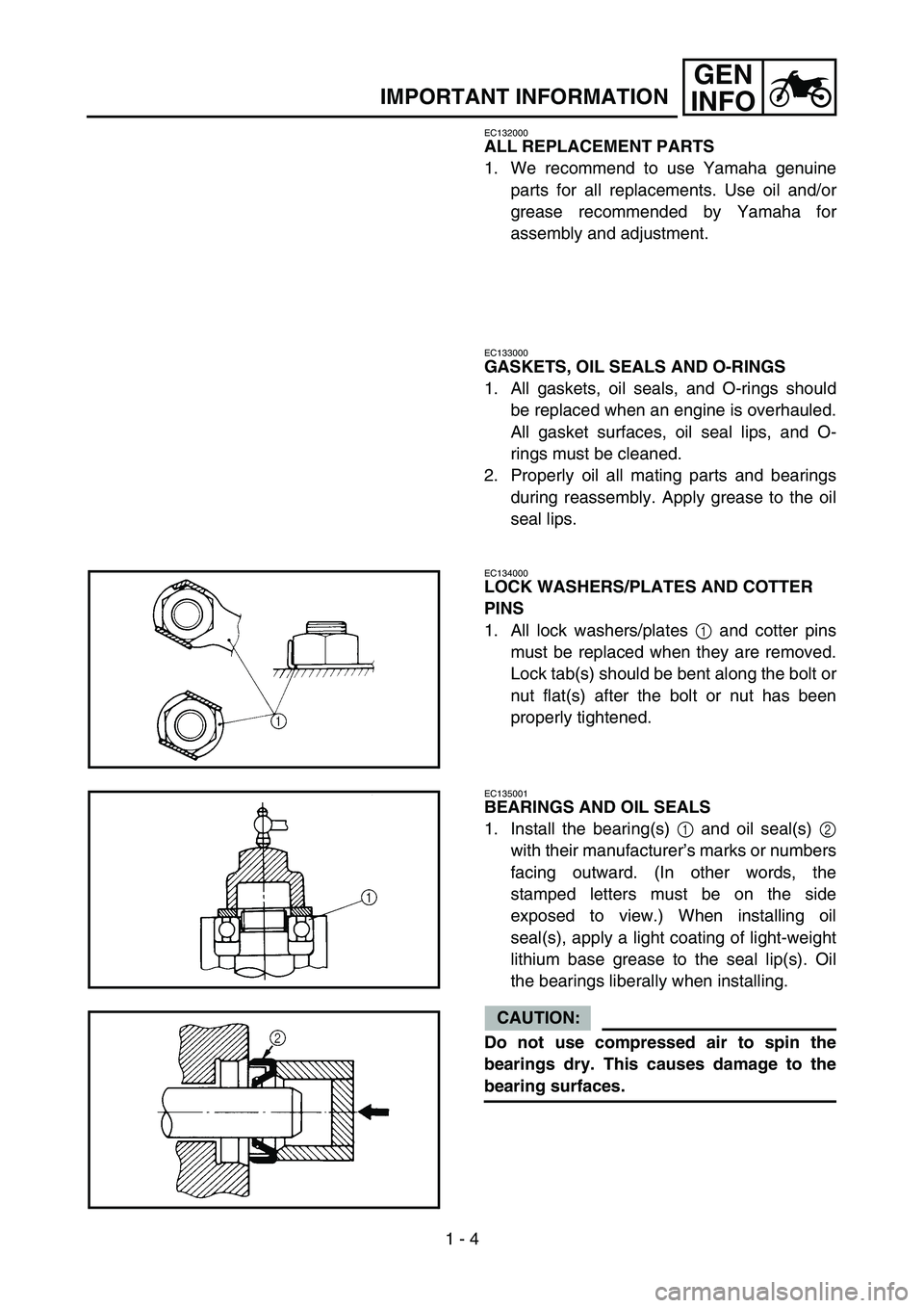
LOCK WASHERS/PLATES AND COTTER
PINS
1. All lock washers/plates 1 and cotter pins
must be replaced when they are removed.
Lock tab(s) should be bent along the bolt or
nut flat(s) after the bolt or nut has been
properly tightened.
EC135001
BEARINGS AND OIL SEALS
1. Install the bearing(s) 1 and oil seal(s) 2
with their manufacturer’s marks or numbers
facing outward. (In other words, the
stamped letters must be on the side
exposed to view.) When installing oil
seal(s), apply a light coating of light-weight
lithium base grease to the seal lip(s). Oil
the bearings liberally when installing.
CAUTION:
Do not use compressed air to spin the
bearings dry. This causes damage to the
bearing surfaces.