Page 185 of 279

9If necessary, the foam insulation may be
removed from the door. First remove the
speaker as described in Chapter 12.
10On models with manual windows, remove
the foam spacer from the regulator spindle
(see illustration).
11On the rear door, unscrew the screws and
remove the door pull bracket (see
illustration).
12Carefully cut the adhesive with a knife,
and remove the foam insulation (see
illustration).
Refitting
13Refitting is a reversal of the removal
procedure.
Removal
Front (manual/non-electric)
1Disconnect the battery negative (earth) lead
(Chapter 5, Section 1).
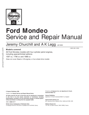
2Remove the door inner trim panel (Sec-
tion 11).
3Remove the door exterior mirror (Sec-
tion 16).
4Temporarily refit the regulator handle on its
splines.
5Lower the window until the glass support
bracket is visible through the holes in the door
inner panel. Remove the regulator handle.
12 Door window glass -
removal and refitting
11•8 Bodywork and fittings
11.8B . . . remove the inner-facing
screws . . .11.8C . . . and the side screws . . .11.8D . . . then lift off the trim panel
11.10 Removing the foam spacer11.11 Removing the door pull bracket
from a rear door11.12 Removing the foam insulation
11.8E Door trim panel components
1 Door
2 Foam seal
3 Trim panel
4 Top mounting
5 Centre mounting
procarmanuals.com
Page 186 of 279

6Carefully prise off the weatherstrip from the
outside of the door.
7Support the glass, then unscrew the bolts
from the support bracket.
8Lift the glass from the door while tilting it at
the rear, and withdraw it from the outside.
Front (electric)
9Disconnect the battery negative (earth) lead
(Chapter 5, Section 1).
10Remove the door inner trim panel (Sec-
tion 11).
11Remove the door exterior mirror (Section 16).
12Temporarily reconnect the battery and the
window operating switch. Lower the window
until the support bracket and bolts are visible
through the holes in the door inner panel (see
illustration). Disconnect the battery lead and
the operating switch again.
13Carefully prise off the weatherstrip from
the outside of the door (see illustration).
14Support the glass, then unscrew the bolts
from the support bracket.
15Lift the glass from the door while tilting it
at the rear, and withdraw it from the outside
(see illustration).
Rear (manual/non-electric)
16Disconnect the battery negative (earth)
lead (Chapter 5, Section 1).
17Remove the door inner trim panel (Sec-
tion 11).
18Temporarily refit the regulator handle on
its splines.19Lower the window until the glass support
bracket and bolts are visible through the holes
in the door inner panel. Remove the regulator
handle.
20Support the glass, then unscrew the bolts
from the support bracket.
21Unscrew the screws, and remove the air
vent grilles from the rear of the rear door (see
illustrations).
22Carefully prise off the weatherstrip from
the outside of the door.
23Have an assistant raise the glass from the
outside, and hold it near its shut position.
24Loosen (but do not remove) the three
regulator mounting bolts, then slide the top
bolts to the right, and push them out. Slide the
bottom bolt upwards, and push it out. Lower
the regulator assembly inside the door.
25Working inside the door, lower the glass
until it is below the regulator position, and
move the glass to the outer side of its
channels.
26With the help of an assistant, lift the glass
out of the door, and withdraw it from the
outside (see illustration).
Rear (electric)
27The procedure is as just described for
manual windows, making allowances for the
difference in the regulator mechanism.
Refitting
All doors
28Refitting is a reversal of the removalprocedure, making sure that the glass is
correctly located in the support bracket.
Removal
1Remove the window glass (Section 12).
2Loosen (but do not remove) the regulator
and manual winder/electric motor mounting
bolts (see illustrations).
3Twist the winder or motor (as applicable) in
the bolt slots, and push it inwards.
4Slide the top bolts to the right, and push
them out. Slide the bottom bolt upwards, and
push it out.
13 Door window regulator-
removal and refitting
Bodywork and fittings 11•9
11
12.21B . . . and remove the air vent grilles
from the rear door12.26 Lifting the glass from the rear door13.2A Window regulator upper mounting
bolts (front door)
12.12 Window support bracket bolts
(arrowed) viewed through the holes in the
door inner panel12.13 Removing the weatherstrip from the
outside of the door12.15 Lifting the glass from the front door
12.21A Unscrew the screws . . .
procarmanuals.com
Page 187 of 279
.
6Withdraw the window regulator mechanism
from inside the door, through the hole in the
inner panel (see illust")
5On electric windows, disconnect the wiring
multi-plug from the motor (see illustration).
6Withdraw the window regulator mechanism
from inside the door, through the hole in the
inner panel (see illustrations).
Refitting
7Refitting is a reversal of the removal
procedure.
Removal
Front door exterior handle
1Remove the door inner trim panel (Sec-
tion 11).
2Use a knife to cut through the adhesive
strip, so that the foam insulator can be peeled
back locally for access to the lock. Do not
peel back the foam insulator without first
cutting through the adhesive strip, otherwise
the insulator will be damaged. To ensure a
good seal when the insulator is pressed back,
do not touch the adhesive strip.
3Unscrew and remove the two bolts for the
exterior handle outer bezel, and remove the
bezel (see illustrations).
14 Door handle and lock
components -
removal and refitting
11•10 Bodywork and fittings
13.2B Electric window motor mounting
bolts (front door)13.2C Window regulator mounting bolts -
arrowed (rear door)13.2D Manual winder mounting bolts (rear
door)
13.5 Disconnecting the wiring multi-plug
from an electrically-operated window13.6A Removing the window regulator
mechanism from the front door
13.6B Front door window regulator
removed from the vehicle13.6C Removing the window regulator
mechanism from the rear door
13.6D Rear door window regulator
removed from the vehicle14.3A Remove the two bolts (arrowed) . . .14.3B . . . followed by the exterior handle
bezel
procarmanuals.com
Page 188 of 279
.
5Unclip and disconnect the wiring mu")
4Unscrew and remove the lock mounting
bolts on the inner rear edge of the door, and
remove the plate. Also remove the additional
support screw (see illustrations).
5Unclip and disconnect the wiring multi-
plugs for the central locking and alarm
systems (see illustration).
6Disconnect the wiring multi-plug from the
door lock.
7Disconnect the inner handle illumination
light. Undo the screws and remove the inner
handle. Disconnect the operating cable from
the inner handle, as described later in this
Section (see illustrations).
8Manipulate the lock and handle assembly
as necessary, and disconnect the wiring
multi-plugs for the alarm sensor and central
locking. Withdraw the complete assembly
from inside the door (see illustrations).
9To disconnect the handle assembly from
the lock bracket, slide the rubber posts
inwards, and push out the assembly (see
illustration).
10To remove the handle itself, twist the door
handle through a quarter-turn, and pull out the
connecting rods (see illustration).
11Remove the alarm sensor and the central
locking “Set-reset” sensor (see illustration).
Rear door exterior handle
12Remove the door inner trim panel (Sec-
tion 11).
13Use a knife to cut through the adhesive
Bodywork and fittings 11•11
11
14.8B Front door lock and exterior handle
assembly removed from the vehicle14.9 Disconnecting the handle assembly
from the lock bracket14.10 Pulling out the handle connecting
rods
14.4A Unscrew the lock mounting
bolts . . .14.4B . . . and remove the plate14.4C Removing the additional support
screw
14.5 Disconnecting the central locking
and alarm system wiring multi-plugs14.7A Removing the inner handle
14.7B Disconnecting the operating cable
from the inner handle14.8A Removing the lock and exterior
handle assembly from inside the door
procarmanuals.com
Page 189 of 279

strip, so that the foam insulator can be peeled
back for access to the lock. Do notpeel back
the foam insulator without first cutting through
the adhesive strip. To ensure a good seal
when the insulator is pressed back, do not
touch the adhesive strip.
14Prise out the plug from the rear edge of
the door, then unscrew the handle mounting
nuts (see illustrations).
15Prise up the clip, and disconnect the
operating rod from the lock (see illustration).
16Withdraw the handle from the outside of
the door (see illustration).
Interior handle
17Remove the door inner trim panel (Sec-
tion 11).
18Use a knife to cut through the adhesive
strip, so that the foam insulator can be peeledback for access to the lock. Do notpeel back
the foam insulator without first cutting through
the adhesive strip. To ensure a good seal
when the insulator is pressed back, do not
touch the adhesive strip.
19Disconnect the interior handle illumination
light.
20Undo the screws and remove the interior
handle.
21To remove the cable, first pull back the
plastic outer cable end and blanking piece.
Apply light inward pressure to the control
lever, with the lever in the locked position,
until the inner cable is aligned with the release
slot in the bottom of the cable holder.
22Push down on the cable ferrule, and
disconnect the inner cable. Remove the
handle assembly.
Lock barrel
23Remove the exterior handle as described
earlier in this Section.
24Prise out the barrel retaining tab from the
handle body, using a small screwdriver (see
illustration).
25Insert the key, turn it so that it engages
the barrel, then pull out the barrel (see
illustration).
Lock motor - front door26Remove the exterior handle as described
earlier in this Section.
27Extract the clip, and pull out the operating
rod.
28Remove the operating rod from the plastic
bush, by turning it through a quarter-turn.
29Release the sensor wiring loom from the
clip.
11•12 Bodywork and fittings
14.11 Removing the central locking “Set-
reset” sensor14.14A Prise out the plug . . .14.14B . . . and unscrew the handle
mounting nuts
14.25 . . . and pull out the lock barrel14.31 Unclipping the door-ajar sensor14.32 Removing the plastic shield from the
locating post
14.15 Disconnect the operating rod from
the lock14.16 Removing the rear door exterior
handle14.24 Prise out the barrel retaining tab . . .
procarmanuals.com
Page 190 of 279
.
32Prise the plastic shield from the locating
post (see illustration).
33Slide the outer cabl")
30Detach the mounting plate from the lock.
31Release the door-ajar sensor from the clip
(see illustration).
32Prise the plastic shield from the locating
post (see illustration).
33Slide the outer cable from the lock
bracket (see illustration), then turn the inner
cable through a quarter-turn to remove it from
the bell crank.
34Unscrew the mounting screws and
remove the lock motor (see illustration).
Lock motor - rear door
35Remove the exterior handle as described
earlier in this Section.
36Unscrew and remove the three lock
mounting screws.
37Release the sensor wiring loom from the
clip on the door.
38Disconnect the wiring multi-plug from the
door lock.
39Disconnect the interior handle illumination
light.
40Remove the screws, and remove the
interior handle.
41Remove the lock assembly.
42Release the door-ajar sensor from the
clip.
43Prise the plastic shield from the locating
post.
44Slide the outer cable from the lock
bracket, then turn the inner cable through a
quarter-turn to remove it from the bell crank.
45Unscrew the mounting screws andremove the lock motor.
Striker
46Using a pencil, mark the position of the
striker.
47Undo the mounting screws using a Torx
key, and remove the striker.
Check strap
48Disconnect the battery negative (earth)
lead (Chapter 5, Section 1).
49Using a Torx key, unscrew and remove
the check strap mounting screw(s). On the
front door, there are two screws; on the rear
door, there is only one.
50Prise the rubber grommet from the door
aperture, then unscrew the mounting nuts and
withdraw the check strap from the door.
Refitting
Handles (exterior and interior)
51Refitting is a reversal of the removal
procedure.
Lock barrel
52Check that the retaining clip is fitted
correctly.
53Align the grooves on the barrel with the
grooves on the body and operating lever, then
carefully push the barrel into the handle until it
engages the clip.
54The remaining refitting procedure is a
reversal of removal.
Lock motor
55Refitting is a reversal of the removal
procedure.
Striker
56Refitting is a reversal of the removal
procedure, but check that the door lock
passes over the striker centrally. If necessary,
re-position the striker before fully tightening
the mounting screws.
Check strap
59Refitting is a reversal of the removal
procedure.
Removal
1Disconnect the battery negative (earth) lead
(Chapter 5, Section 1).
2Using a Torx key, unscrew and remove the
check strap mounting screw(s). On the front
door, there are two screws; on the rear door,
there is only one (see illustrations).
3Disconnect the wiring connector(s) by
twisting them anti-clockwise. On the front
door, there are two connectors; on the rear
door, there is only one (see illustration).
4Extract the small circlips from the top of the
upper and lower hinge pins (see illustration).
5Have an assistant support the weight of the
15 Door - removal and refitting
Bodywork and fittings 11•13
11
15.2B Front door check strap removed15.3 Disconnecting a door wiring
connector15.4 Extract the small circlips . . .
14.33 Slide the outer cable from the lock
bracket14.34 Removing a lock motor15.2A Front door check strap mounting
screw removal
procarmanuals.com
Page 191 of 279
.
6Carefully withdraw the door from the
hinges.
Refitting
7Refitting is a reversal of the removal
procedu")
door, then drive the hinge pins down through
the hinges using a small drift (see
illustrations).
6Carefully withdraw the door from the
hinges.
Refitting
7Refitting is a reversal of the removal
procedure, but check that the door lock
passes over the striker centrally. If necessary,
re-position the striker.
Removal
1Where electric mirrors are fitted, disconnect
the battery negative (earth) lead (Chapter 5,
Section 1).
2Prise off the cap, unscrew the screw, and
remove the quarter bezel from the front of the
window opening.
3On manual mirrors, detach the adjustment
lever.
4On electric mirrors, disconnect the wiring
multi-plug (see illustration).
5On both types of mirror, use a Torx key to
unscrew the mirror mounting screws, then
withdraw the mirror from the outside of the
door (see illustrations). Recover the gasket.
Refitting
6Refitting is a reversal of the removal
procedure.
Removal
1Using a length of strong thin cord or fishing
line, break the adhesive bond between the
base of the mirror and the glass. Have an
assistant support and remove the mirror as it
is released.
2If the original mirror is to be refitted,
thoroughly clean its base with methylated
spirit and a lint-free cloth. Allow a period of
one minute for the spirit to evaporate. Clean
the windscreen black patch in a similar
manner.
Refitting
3During the installation of the mirror, it is
important that the mirror base, windscreen
black patch and the adhesive patch are not
touched or contaminated in any way,
otherwise poor adhesion will result.
4Prior to fitting the mirror, the vehicle should
have been at an ambient temperature of at
least 20ºC.
5With the contact surfaces thoroughly
cleaned, remove the protective tape from one
side of the adhesive patch, and press it firmly
into contact with the mirror base.
6If fitting the mirror to a new windscreen, the
protective tape must also be removed from
the windscreen black patch.
7Using a hairdryer or a hot air gun, warm themirror base and the adhesive patch for about
30 seconds to a temperature of 50 to 70ºC.
Peel back the protective tape from the other
side of the adhesive patch on the mirror base.
Align the mirror base and the windscreen
patch, and press the mirror firmly into
position. Hold the base of the mirror firmly
against the windscreen for a minimum period
of two minutes, to ensure full adhesion.
8Wait at least thirty minutes before adjusting
the mirror position.
Removal
1Disconnect the battery negative (earth) lead
(Chapter 5, Section 1), and open the boot lid.
2Where applicable, pull off the trim covering,
and release the wiring on the hinge arm.
3Where fitted, remove the trim from inside
the boot lid.
4Disconnect the wiring at the connectors
visible through the boot lid inner skin aperture.
5Attach a length of strong cord to the end of
the wires in the aperture, to act as an aid to
guiding the wiring through the lid when it is
refitted.
6Release the cable guide rubber grommet,
and withdraw the wiring loom through it. Untie
the cord, and leave it in the boot lid.
7Mark the position of the hinge arms with a
pencil.
8Place rags beneath each corner of the boot
lid, to prevent damage to the paintwork.
9With the help of an assistant, unscrew the
mounting bolts and lift the boot lid from the
car.
Refitting
10Refitting is a reversal of the removal
procedure. Check that the boot lid is correctly
aligned with the surrounding bodywork, with
an equal clearance around its edge.
Adjustment is made by loosening the hinge
bolts, and moving the boot lid within the
elongated mounting holes. Check that the
lock enters the striker centrally when the boot
lid is closed.
18 Boot lid - removal and refitting
17 Interior mirror -
removal and refitting
16 Exterior mirror and glass-
removal and refitting
11•14 Bodywork and fittings
15.5A . . . then drive out the hinge pins . . .15.5B . . . and remove them16.4 Disconnecting the wiring multi-plug
from an electric exterior mirror
16.5A Unscrew the screws . . .16.5B . . . and withdraw the mirror
procarmanuals.com
Page 192 of 279
 lead
(Chapter 5, Section 1).
2With the boot lid open, remove the luggage
space trim from the right-hand rear corner.
3Remove the screws, an")
Removal
Lock barrel
1Disconnect the battery negative (earth) lead
(Chapter 5, Section 1).
2With the boot lid open, remove the luggage
space trim from the right-hand rear corner.
3Remove the screws, and prise out the rear
light trim cover from the guides.
4Release the door-ajar sensor from the clip
near the lock.
5Slide the outer cable from the lock bracket.
Raise the inner cable until it is aligned with the
slot in the barrel lever, and disconnect it.
6Pull out the lock locating spring clip.
7Detach the cable mounting bracket from
the barrel, and remove the barrel.
Lock
8Disconnect the battery negative (earth) lead
(Chapter 5, Section 1).
9With the boot lid open, prise out the clips
and remove the trim from inside the boot lid.
10Release the door-ajar sensor from the clip
near the lock.
11Using a Torx key, unscrew the lock
mounting screws, and withdraw the lock for
access to the cables.
12Disconnect both the inner and outer
cables from the lock bracket.13Prise open the plastic lip, and remove the
central locking control rod.
14Withdraw the lock assembly.
Refitting
Lock barrel and lock
15Refitting is a reversal of the removal
procedure.
Removal
Hatchback
1Disconnect the battery negative (earth) lead
(Chapter 5, Section 1). Open the tailgate.
2The tailgate may be unbolted from the
hinges and the hinges left in position, or the
hinges may be detached from the roof panel
by unscrewing the mounting nuts. In the latter
case, carefully pull down the rear edge of the
headlining for access to the nuts. Take care
not to damage the headlining.
3Remove the parcel shelf left-hand support
bracket as follows. Fold the rear seat
forwards, and disconnect the left-hand seat
pull cable from the bracket and clips.
Unscrew the screws and remove the bracket.
4Pull up the rear seat side bolster, then
carefully remove the side trim from the left-
hand side of the luggage area. On low-series
models, the bolster is retained with a screw.5Separate the tailgate wiring loom multi-
plugs, located on the left-hand side of the
luggage compartment, on top of the wheel
arch.
6Unclip and remove the upper trim panel
from the inside of the tailgate. Also remove
the rear shelf cord plastic post (see
illustrations).
7Prise out the rubber grommet from the top
of the tailgate aperture, and pull the wiring
loom out through the hole in the body (see
illustration).
8Disconnect the rear window washer tube
from the jet.
9Prise out the rubber grommet from the
right-hand side of the tailgate aperture, and
pull out the washer tube.
10Have an assistant support the tailgate in
its open position.
11Using a small screwdriver, prise off the
clips securing the struts to the tailgate. Pull
the sockets from the ball-studs, and move the
struts downwards.
12If the headlining has been pulled back,
unscrew and remove the hinge nuts from the
roof panel. Otherwise, unscrew the bolts
securing the tailgate to the hinges (see
illustration).
13Withdraw the tailgate from the body
aperture, taking care not to damage the
paintwork.
Estate
14Disconnect the battery negative (earth)
lead (Chapter 5, Section 1).
15The tailgate may be unbolted from the
hinges and the hinges left in position, or the
hinges may be detached from the rear roof
panel by unscrewing the mounting nuts. In the
latter case, carefully pull down the rear edge
of the headlining for access to the nuts. Take
care not to damage the headlining.
16Unscrew the retaining screws, then unclip
the “D” pillar trim panels from both sides (see
illustration).
17Unclip and remove the upper trim panel
from inside the tailgate.
18Carefully remove the side trim from the
left-hand side of the luggage area, and
separate the tailgate wiring loom multi-plugs
in the rear light cluster housing.
20 Tailgate -
removal and refitting
19 Boot lid lock components-
removal and refitting
Bodywork and fittings 11•15
11
20.12 Unscrewing the bolts securing the
tailgate to the hinges20.16 “D” pillar trim panel retaining
screws (arrowed) - Estate models
20.6A Unclipping the upper trim panel
from the tailgate20.6B Shelf cord post removal20.7 Removing the wiring loom rubber
grommet
procarmanuals.com
 1
1 2
2 3
3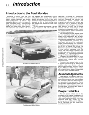 4
4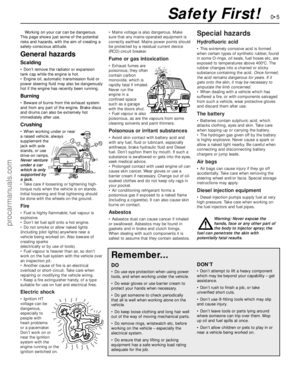 5
5 6
6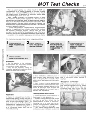 7
7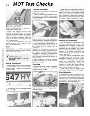 8
8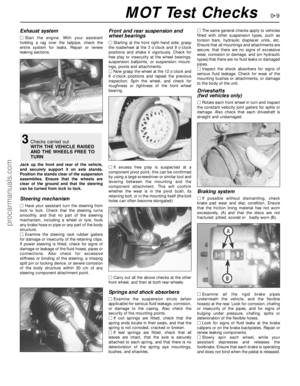 9
9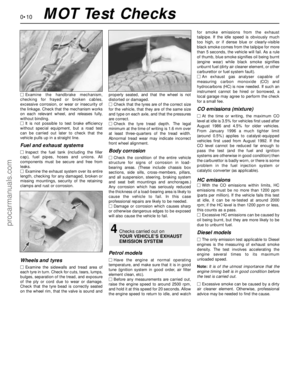 10
10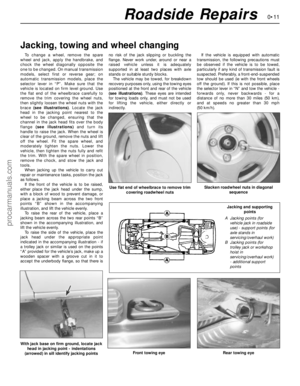 11
11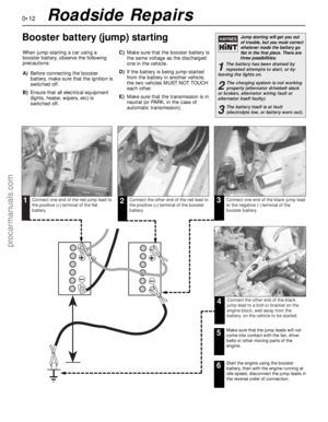 12
12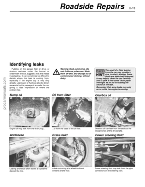 13
13 14
14 15
15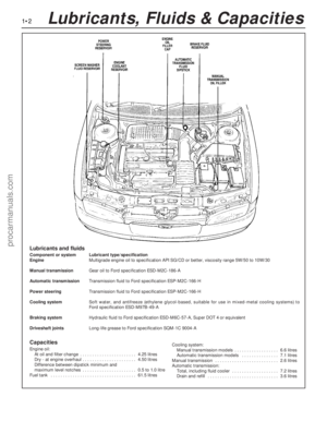 16
16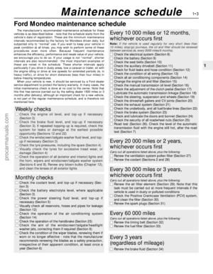 17
17 18
18 19
19 20
20 21
21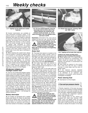 22
22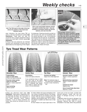 23
23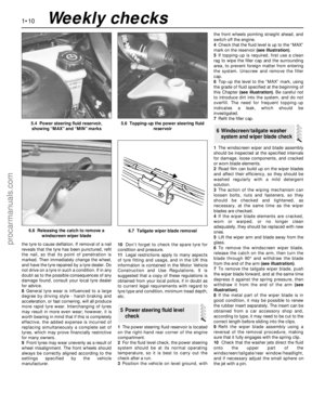 24
24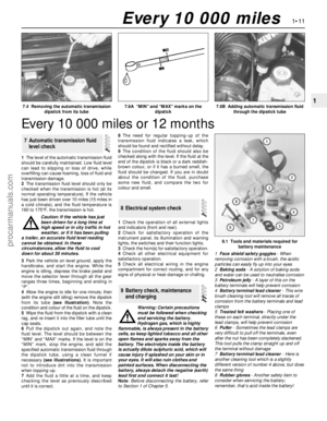 25
25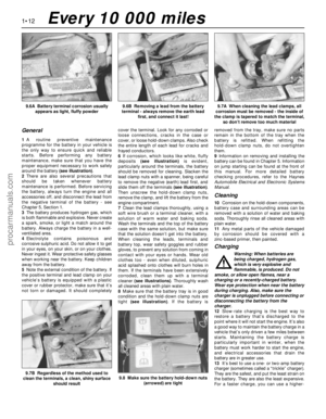 26
26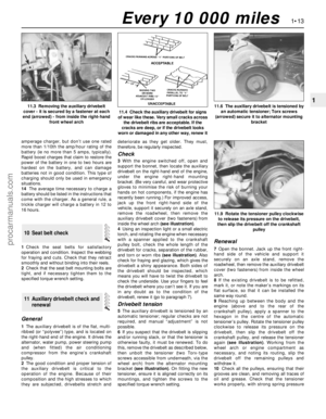 27
27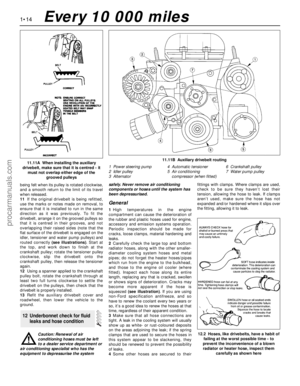 28
28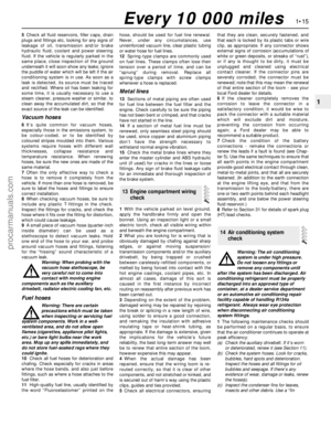 29
29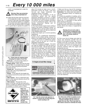 30
30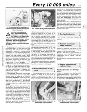 31
31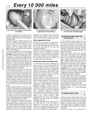 32
32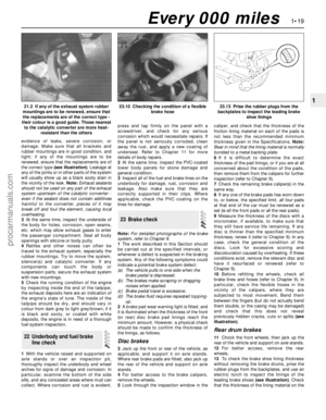 33
33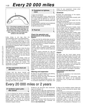 34
34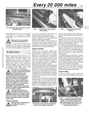 35
35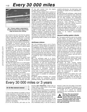 36
36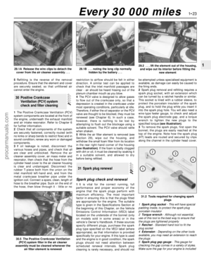 37
37 38
38 39
39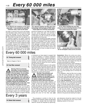 40
40 41
41 42
42 43
43 44
44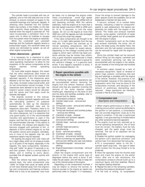 45
45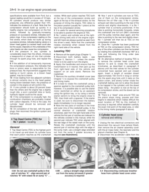 46
46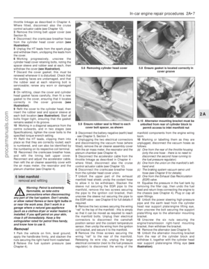 47
47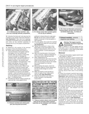 48
48 49
49 50
50 51
51 52
52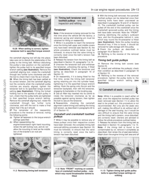 53
53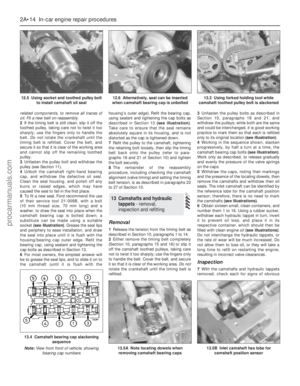 54
54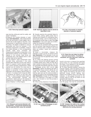 55
55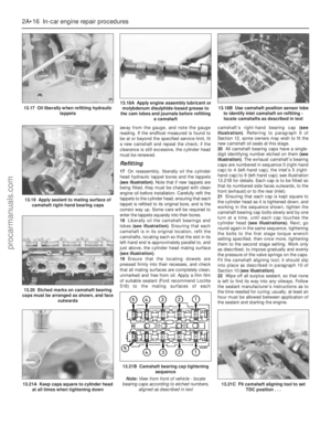 56
56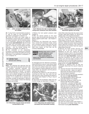 57
57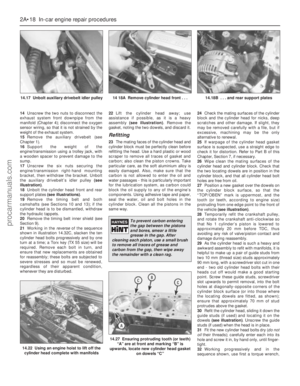 58
58 59
59 60
60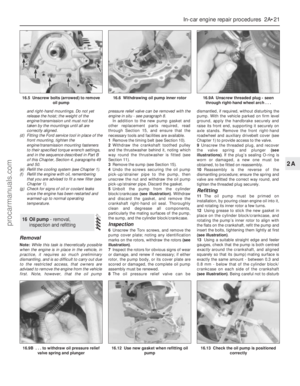 61
61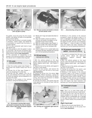 62
62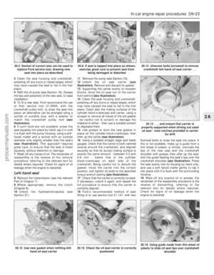 63
63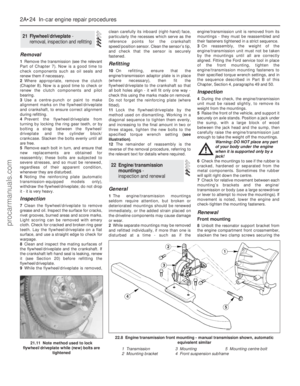 64
64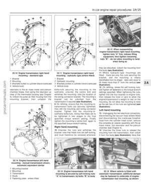 65
65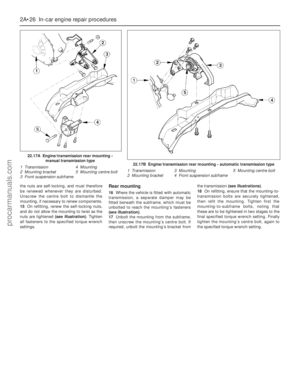 66
66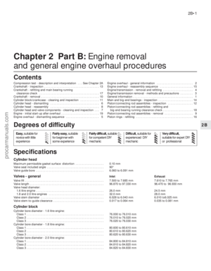 67
67 68
68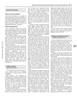 69
69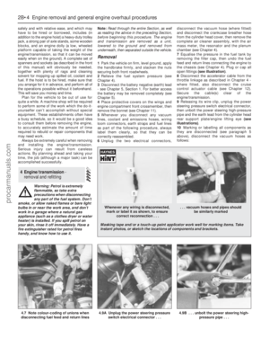 70
70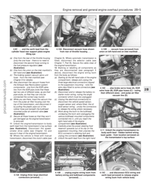 71
71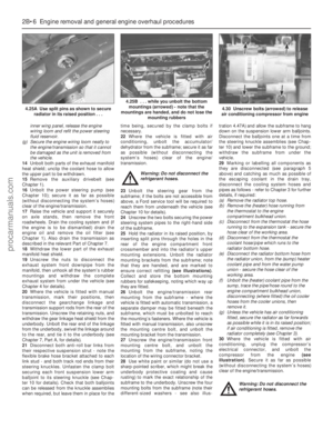 72
72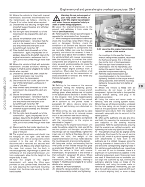 73
73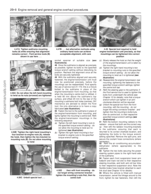 74
74 75
75 76
76 77
77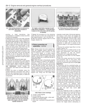 78
78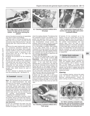 79
79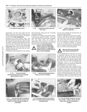 80
80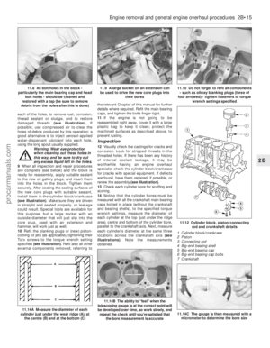 81
81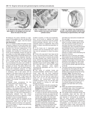 82
82 83
83 84
84 85
85 86
86 87
87 88
88 89
89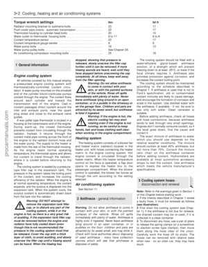 90
90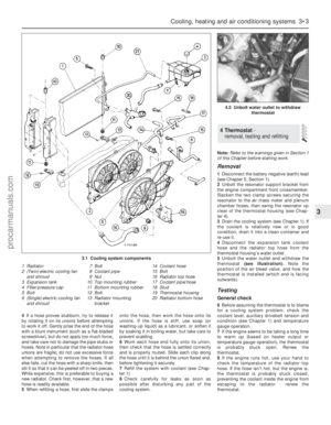 91
91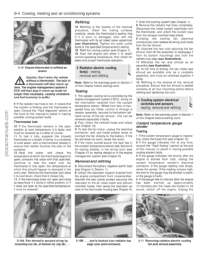 92
92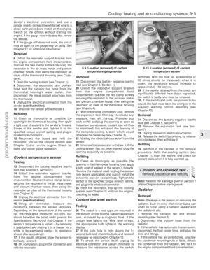 93
93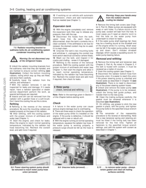 94
94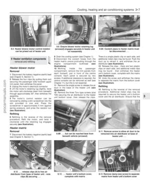 95
95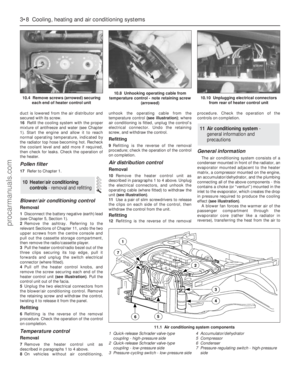 96
96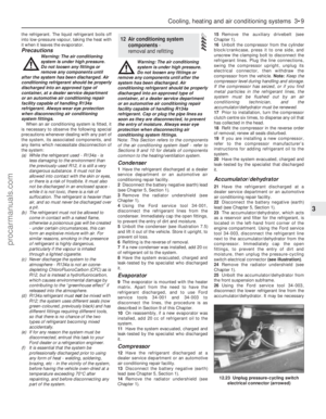 97
97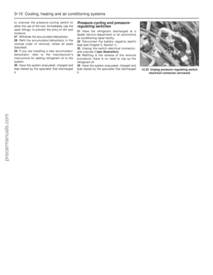 98
98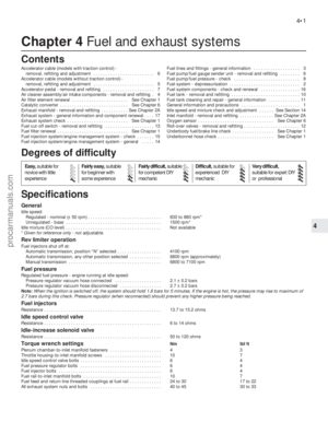 99
99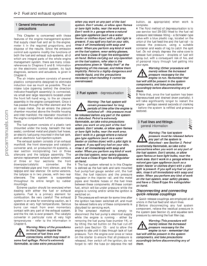 100
100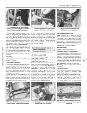 101
101 102
102 103
103 104
104 105
105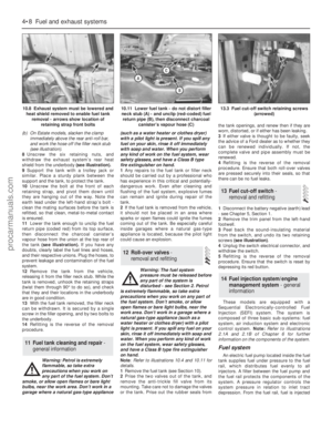 106
106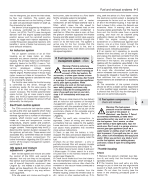 107
107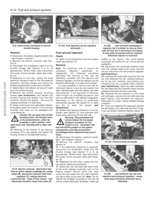 108
108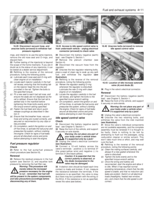 109
109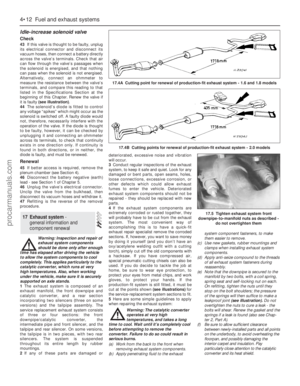 110
110 111
111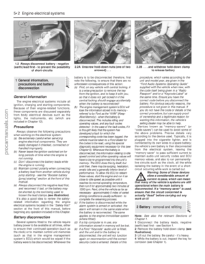 112
112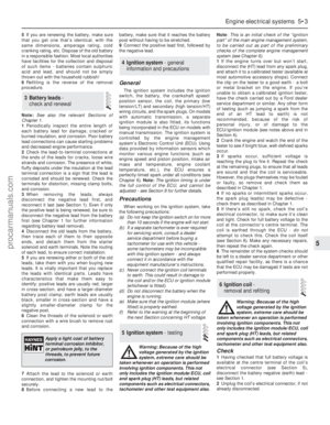 113
113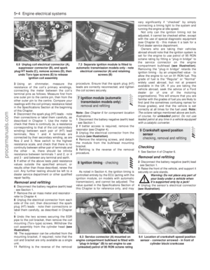 114
114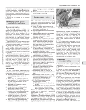 115
115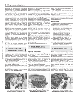 116
116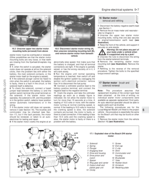 117
117 118
118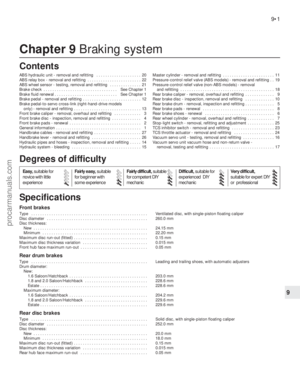 119
119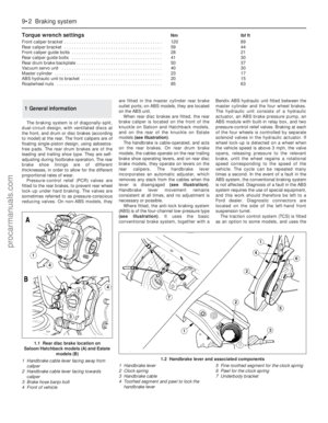 120
120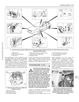 121
121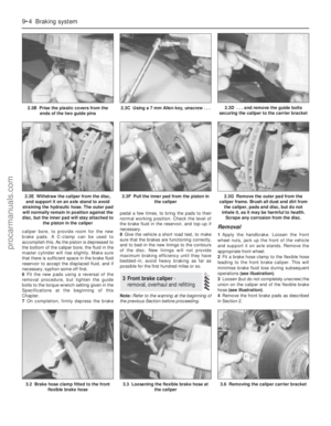 122
122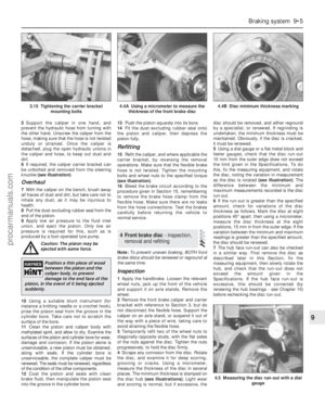 123
123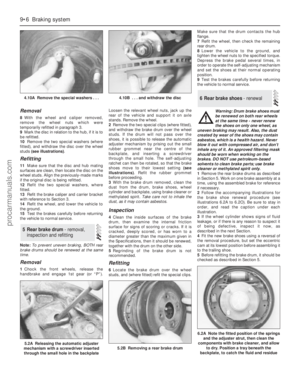 124
124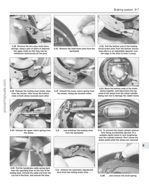 125
125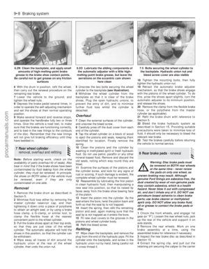 126
126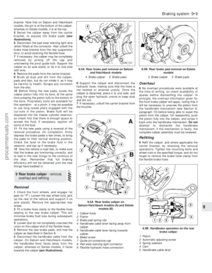 127
127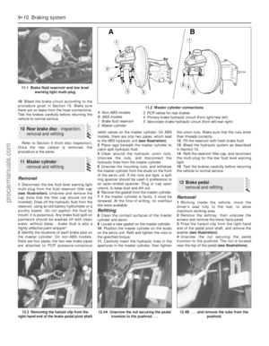 128
128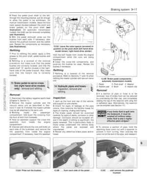 129
129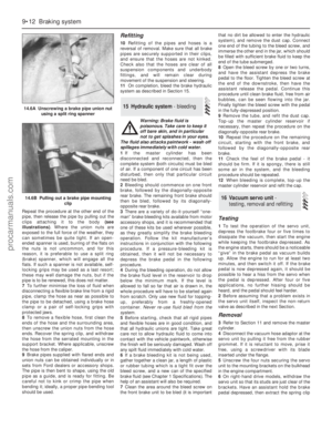 130
130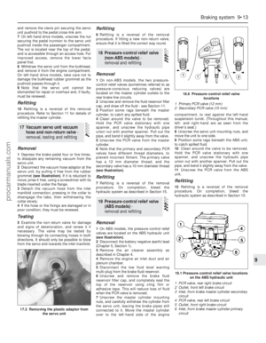 131
131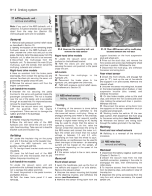 132
132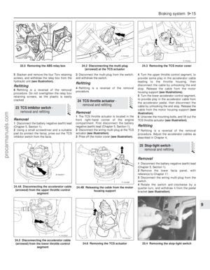 133
133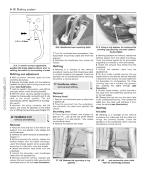 134
134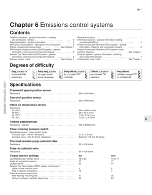 135
135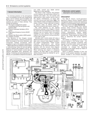 136
136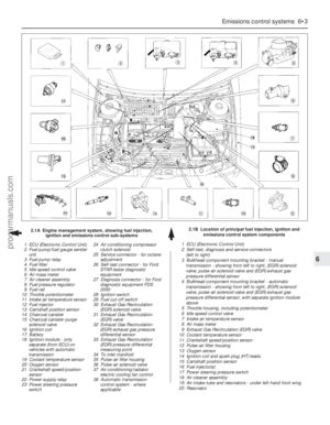 137
137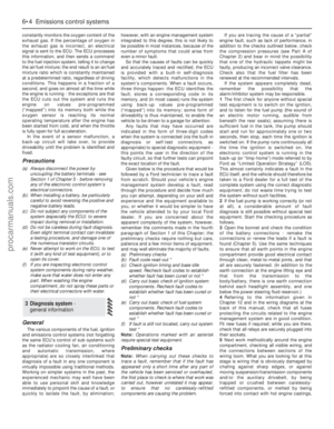 138
138 139
139 140
140 141
141 142
142 143
143 144
144 145
145 146
146 147
147 148
148 149
149 150
150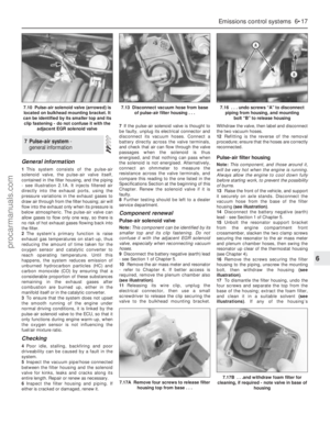 151
151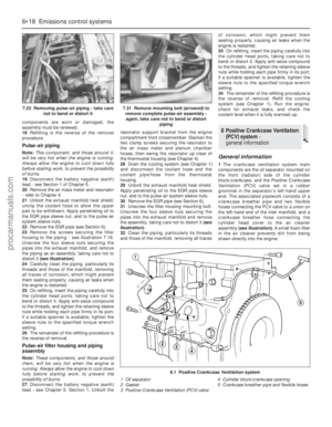 152
152 153
153 154
154 155
155 156
156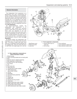 157
157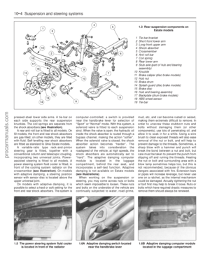 158
158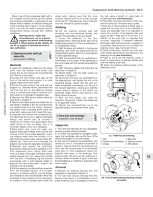 159
159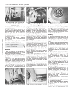 160
160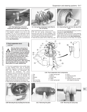 161
161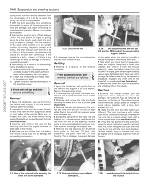 162
162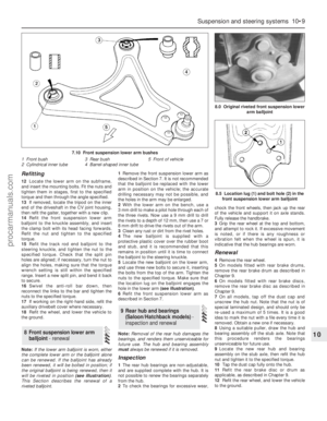 163
163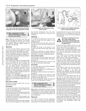 164
164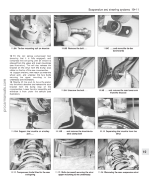 165
165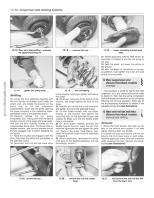 166
166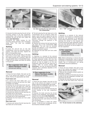 167
167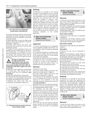 168
168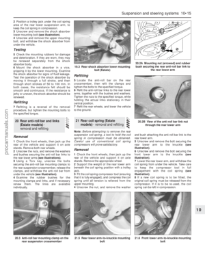 169
169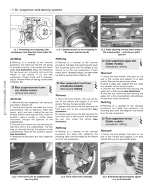 170
170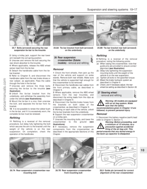 171
171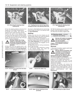 172
172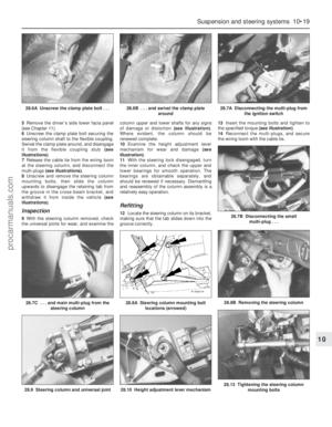 173
173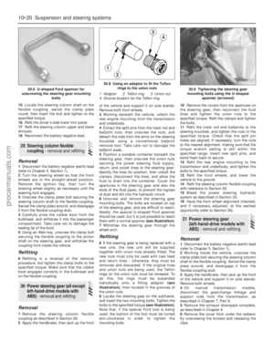 174
174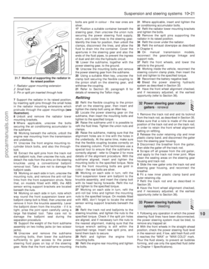 175
175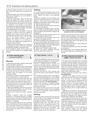 176
176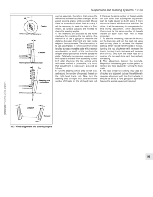 177
177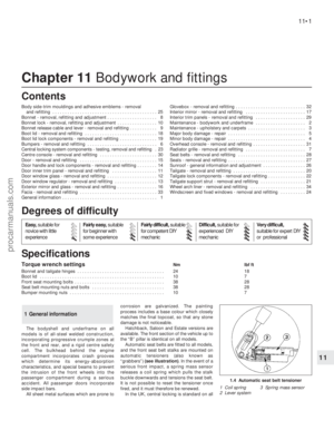 178
178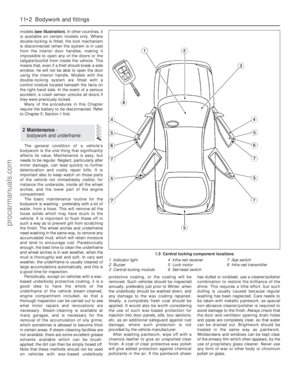 179
179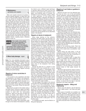 180
180 181
181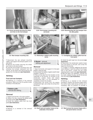 182
182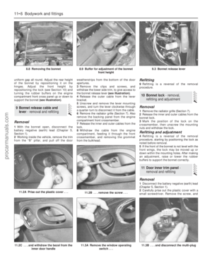 183
183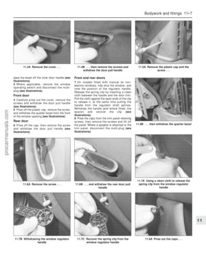 184
184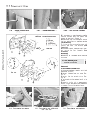 185
185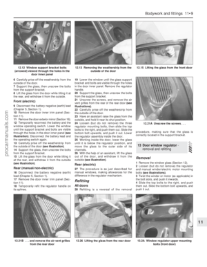 186
186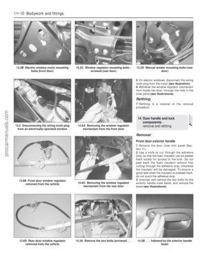 187
187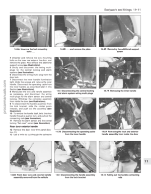 188
188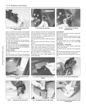 189
189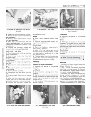 190
190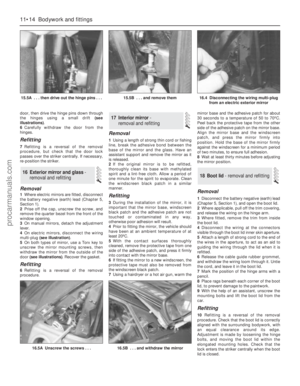 191
191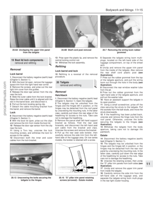 192
192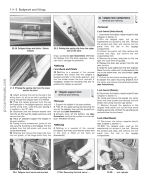 193
193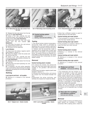 194
194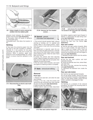 195
195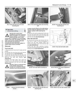 196
196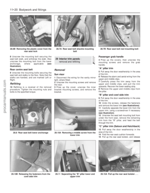 197
197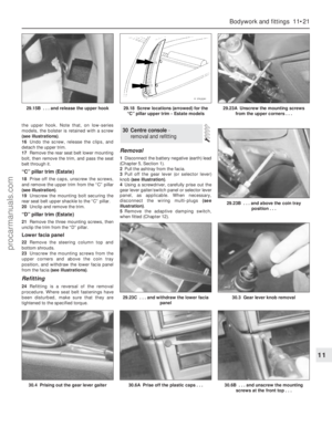 198
198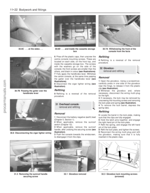 199
199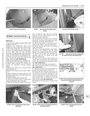 200
200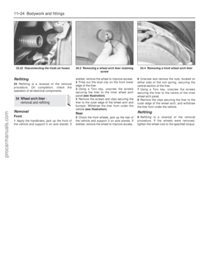 201
201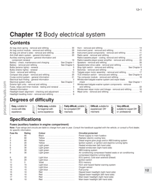 202
202 203
203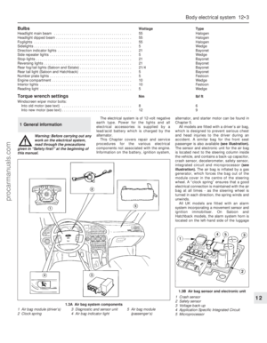 204
204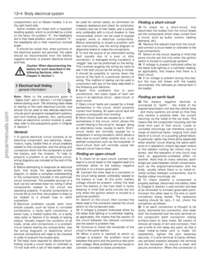 205
205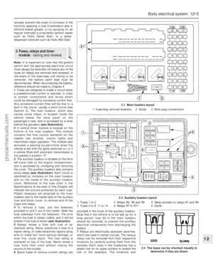 206
206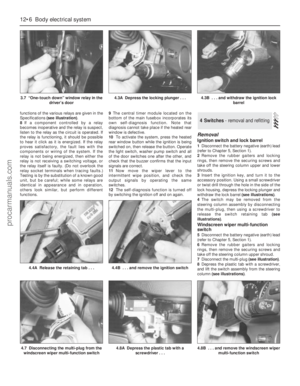 207
207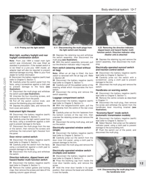 208
208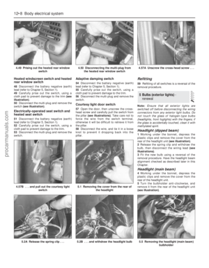 209
209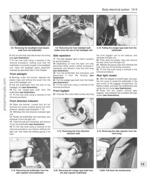 210
210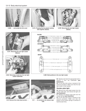 211
211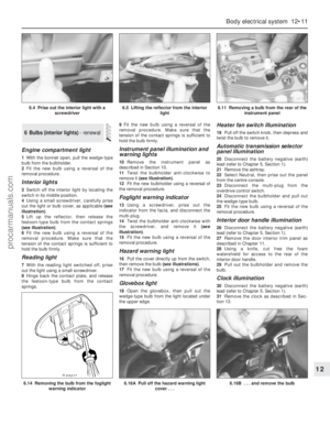 212
212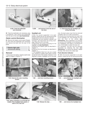 213
213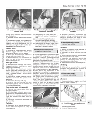 214
214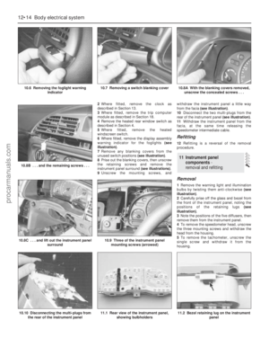 215
215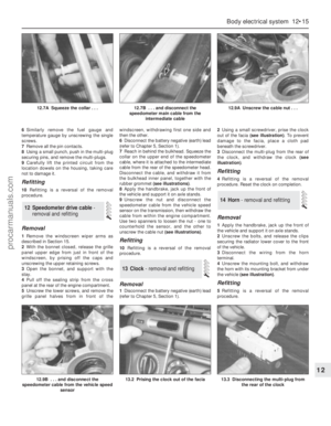 216
216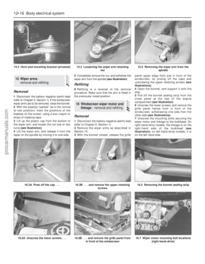 217
217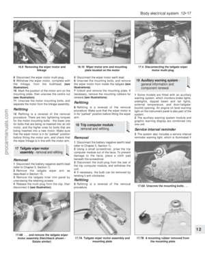 218
218 219
219 220
220 221
221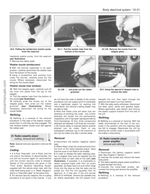 222
222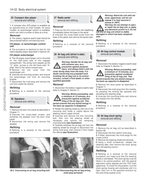 223
223 224
224 225
225 226
226 227
227 228
228 229
229 230
230 231
231 232
232 233
233 234
234 235
235 236
236 237
237 238
238 239
239 240
240 241
241 242
242 243
243 244
244 245
245 246
246 247
247 248
248 249
249 250
250 251
251 252
252 253
253 254
254 255
255 256
256 257
257 258
258 259
259 260
260 261
261 262
262 263
263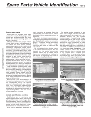 264
264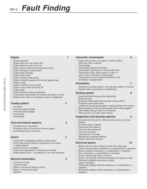 265
265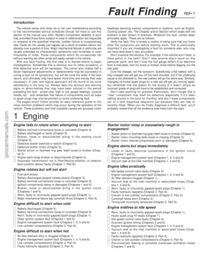 266
266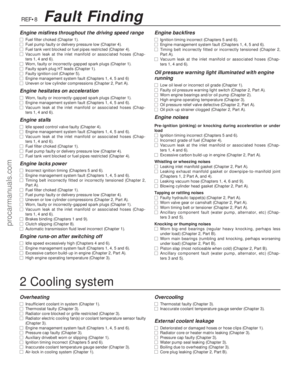 267
267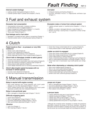 268
268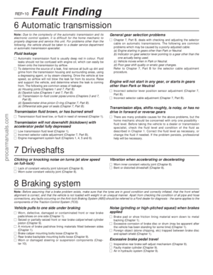 269
269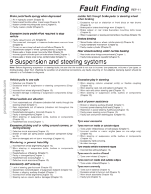 270
270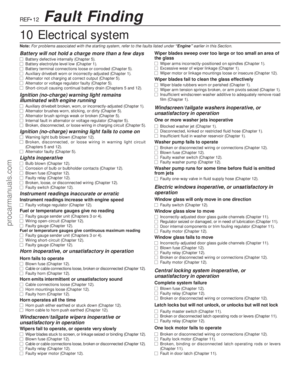 271
271 272
272 273
273 274
274 275
275 276
276 277
277 278
278