1993 FORD MONDEO steering wheel adjustment
[x] Cancel search: steering wheel adjustmentPage 7 of 279
0•7
This is a guide to getting your vehicle through the MOT test.
Obviously it will not be possible to examine the vehicle to the same
standard as the professional MOT tester. However, working through
the following checks will enable you to identify any problem areas
before submitting the vehicle for the test.
Where a testable component is in borderline condition, the tester
has discretion in deciding whether to pass or fail it. The basis of such
discretion is whether the tester would be happy for a close relative or
friend to use the vehicle with the component in that condition. If the
vehicle presented is clean and evidently well cared for, the tester may
be more inclined to pass a borderline component than if the vehicle is
scruffy and apparently neglected.
It has only been possible to summarise the test requirements here,
based on the regulations in force at the time of printing. Test standards
are becoming increasingly stringent, although there are some
exemptions for older vehicles. For full details obtain a copy of the Haynes
publication Pass the MOT! (available from stockists of Haynes manuals).
An assistant will be needed to help carry out some of these checks.
The checks have been sub-divided into four categories, as follows:
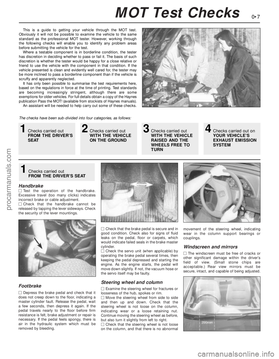
HandbrakeMTest the operation of the handbrake.
Excessive travel (too many clicks) indicates
incorrect brake or cable adjustment.
MCheck that the handbrake cannot be
released by tapping the lever sideways. Check
the security of the lever mountings.
Footbrake
MDepress the brake pedal and check that it
does not creep down to the floor, indicating a
master cylinder fault. Release the pedal, wait
a few seconds, then depress it again. If the
pedal travels nearly to the floor before firm
resistance is felt, brake adjustment or repair is
necessary. If the pedal feels spongy, there is
air in the hydraulic system which must be
removed by bleeding.MCheck that the brake pedal is secure and in
good condition. Check also for signs of fluid
leaks on the pedal, floor or carpets, which
would indicate failed seals in the brake master
cylinder.
MCheck the servo unit (when applicable) by
operating the brake pedal several times, then
keeping the pedal depressed and starting the
engine. As the engine starts, the pedal will
move down slightly. If not, the vacuum hose or
the servo itself may be faulty.
Steering wheel and column
MExamine the steering wheel for fractures or
looseness of the hub, spokes or rim.
MMove the steering wheel from side to side
and then up and down. Check that the
steering wheel is not loose on the column,
indicating wear or a loose retaining nut.
Continue moving the steering wheel as before,
but also turn it slightly from left to right.
MCheck that the steering wheel is not loose
on the column, and that there is no abnormalmovement of the steering wheel, indicating
wear in the column support bearings or
couplings.
Windscreen and mirrors
MThe windscreen must be free of cracks or
other significant damage within the driver’s
field of view. (Small stone chips are
acceptable.) Rear view mirrors must be
secure, intact, and capable of being adjusted.
1Checks carried out
FROM THE DRIVER’S SEAT
MOT Test Checks
1Checks carried out
FROM THE DRIVER’S
SEAT2Checks carried out
WITH THE VEHICLE
ON THE GROUND3Checks carried out
WITH THE VEHICLE
RAISED AND THE
WHEELS FREE TO
TURN4Checks carried out on
YOUR VEHICLE’S
EXHAUST EMISSION
SYSTEM
procarmanuals.com
Page 15 of 279
Chapter 1 Routine maintenance and servicing
Air conditioning system check . . . . . . . . . . . . . . . . . . . . . . . . . . . . . 14
Air filter element renewal . . . . . . . . . . . . . . . . . . . . . . . . . . . . . . . . . . 29
Automatic transmission fluid level check . . . . . . . . . . . . . . . . . . . . . 7
Automatic transmission linkage lubrication . . . . . . . . . . . . . . . . . . . 18
Auxiliary drivebelt check and renewal . . . . . . . . . . . . . . . . . . . . . . . . 11
Battery check, maintenance and charging . . . . . . . . . . . . . . . . . . . . 9
Brake check . . . . . . . . . . . . . . . . . . . . . . . . . . . . . . . . . . . . . . . . . . . 23
Brake fluid renewal . . . . . . . . . . . . . . . . . . . . . . . . . . . . . . . . . . . . . . 34
Clutch pedal adjustment . . . . . . . . . . . . . . . . . . . . . . . . . . . . . . . . . . 17
Coolant renewal . . . . . . . . . . . . . . . . . . . . . . . . . . . . . . . . . . . . . . 2, 28
Door and bonnet check and lubrication . . . . . . . . . . . . . . . . . . . . . . 24
Driveshaft rubber gaiter and CV joint check . . . . . . . . . . . . . . . . . . . 20
Electrical system check . . . . . . . . . . . . . . . . . . . . . . . . . . . . . . . . . . . 8
Engine compartment wiring check . . . . . . . . . . . . . . . . . . . . . . . . . . 13
Engine oil and filter change . . . . . . . . . . . . . . . . . . . . . . . . . . . . . . . . 15
Exhaust system check . . . . . . . . . . . . . . . . . . . . . . . . . . . . . . . . . . . 21
Fluid level checks . . . . . . . . . . . . . . . . . . . . . . . . . . . . . . . . . . . . . . . 3
Fuel filter renewal . . . . . . . . . . . . . . . . . . . . . . . . . . . . . . . . . . . . . . . 33
Idle speed and mixture check and adjustment . . . . . . See Chapter 4Ignition timing check . . . . . . . . . . . . . . . . . . . . . . . . . . See Chapter 5
Introduction . . . . . . . . . . . . . . . . . . . . . . . . . . . . . . . . . . . . . . . . . . . . 1
Manual transmission oil level check . . . . . . . . . . . . . . . . . . . . . . . . . 16
Positive Crankcase Ventilation (PCV) system check
and filter cleaning . . . . . . . . . . . . . . . . . . . . . . . . . . . . . . . . . . . . . 30
Power steering fluid level check . . . . . . . . . . . . . . . . . . . . . . . . . . . . 5
Road test . . . . . . . . . . . . . . . . . . . . . . . . . . . . . . . . . . . . . . . . . . . . . . 26
Roadwheel nut tightness check . . . . . . . . . . . . . . . . . . . . . . . . . . . . 25
Seat belt check . . . . . . . . . . . . . . . . . . . . . . . . . . . . . . . . . . . . . . . . . 10
Spark plug renewal . . . . . . . . . . . . . . . . . . . . . . . . . . . . . . . . . . . . . . 31
Specifications . . . . . . . . . . . . . . . . . . . . . . . . . . . . See end of Chapter
Steering, suspension and roadwheel check . . . . . . . . . . . . . . . . . . . 19
Timing belt renewal . . . . . . . . . . . . . . . . . . . . . . . . . . . . . . . . . . . . . . 32
Tyre and tyre pressure checks . . . . . . . . . . . . . . . . . . . . . . . . . . . . . 4
Underbody and fuel/brake line check . . . . . . . . . . . . . . . . . . . . . . . . 22
Underbonnet check for fluid leaks and hose condition . . . . . . . . . . 12
Ventilation system pollen filter renewal . . . . . . . . . . . . . . . . . . . . . . . 27
Windscreen/tailgate washer system and wiper blade check . . . . . . 6
1•1
Easy,suitable for
novice with little
experienceFairly easy,suitable
for beginner with
some experienceFairly difficult,suitable
for competent DIY
mechanicDifficult,suitable for
experienced DIY
mechanicVery difficult,
suitable for expert DIY
or professional
Degrees of difficulty Contents
1
procarmanuals.com
Page 17 of 279
Ford Mondeo maintenance schedule
1•3
1
Maintenance schedule
The manufacturer’s recommended maintenance schedule for these
vehicles is as described below - note that the schedule starts from the
vehicle’s date of registration. These are the minimum maintenance
intervals recommended by the factory for Mondeos driven daily, but
subjected only to “normal” use. If you wish to keep your vehicle in
peak condition at all times, you may wish to perform some of these
procedures even more often. Because frequent maintenance
enhances the efficiency, performance and resale value of your vehicle,
we encourage you to do so. If your usage is not “normal”, shorter
intervals are also recommended - the most important examples of
these are noted in the schedule. These shorter intervals apply
particularly if you drive in dusty areas, tow a caravan or trailer, sit with
the engine idling or drive at low speeds for extended periods (ie, in
heavy traffic), or drive for short distances (less than four miles) in
below-freezing temperatures.
When your vehicle is new, it should be serviced by a Ford dealer
service department to protect the factory warranty. In many cases, the
initial maintenance check is done at no cost to the owner. Note that
this first free service (carried out by the selling dealer 1500 miles or 3
months after delivery), although an important check for a new vehicle,
is not part of the regular maintenance schedule, and is therefore not
mentioned here.
Weekly checks
m mCheck the engine oil level, and top-up if necessary
(Section 3)
m mCheck the brake fluid level, and top-up if necessary
(Section 3). If repeated topping-up is required, check the
system for leaks or damage at the earliest possible
opportunity (Sections 12 and 22)
m mCheck the windscreen/tailgate washer fluid level, and top-
up if necessary (Section 3)
m mCheck the tyre pressures, including the spare (Section 4)
m mVisually check the tyres for excessive tread wear, or
damage (Section 4)
m mCheck the operation of all (exterior and interior) lights and
the horn, wipers and windscreen/tailgate washer system
(Sections 6 and 8). Renew any blown bulbs (Chapter 12),
and clean the lenses of all exterior lights
Monthly checks
m mCheck the coolant level, and top-up if necessary (Sec-
tion 3)
m mCheck the battery electrolyte level, where applicable
(Section 3)
m mCheck the power steering fluid level, and top-up if
necessary (Section 5)
m mVisually check all reservoirs, hoses and pipes for leakage
(Section 12)
m mCheck the operation of the air conditioning system
(Section 14)
m mCheck the operation of the handbrake (Section 23)
m mCheck the aim of the windscreen/tailgate/headlight
washer jets, correcting them if required (Section 6)
m mCheck the condition of the wiper blades, renewing them if
worn or no longer effective - note that the manufacturer
recommends renewing the blades as a safety precaution,
irrespective of their apparent condition, at least once a
year (Section 6)
Every 10 000 miles or 12 months,
whichever occurs first
Note:If the vehicle is used regularly for very short (less than
10 miles), stop/go journeys, the oil and filter should be renewed
between services (ie, every 5000 miles/6 months).
m mCheck the electrical system (Section 8)
m mCheck the battery (Section 9)
m mCheck the seat belts (Section 10)
m mCheck the auxiliary drivebelt (Section 11)
m mCheck for fluid leaks and hose condition (Section 12)
m mCheck the condition of all wiring (Section 13)
m mCheck all air conditioning components (Section 14)
m mChange the engine oil and filter (Section 15)
m mCheck the manual transmission oil level (Section 16)
m mCheck the adjustment of the clutch pedal (Section 17)
m mLubricate the automatic transmission linkage (Section 18)
m mCheck the steering, suspension and wheels (Section 19)
m mCheck the driveshaft gaiters and CV joints (Section 20)
m mCheck the exhaust system (Section 21)
m mCheck the underbody, and all fuel/brake lines (Section 22)
m mCheck the brake system (Section 23)
m mCheck and lubricate the doors and bonnet (Section 24)
m mCheck the security of all roadwheel nuts (Section 25)
m mRoad test (Section 26). Check the level of the automatic
transmission fluid with the engine still hot, after the road
test (Section 7)
Every 20 000 miles or 2 years,
whichever occurs first
Carry out all operations listed above, plus the following:
m mRenew the ventilation system pollen filter (Section 27)
m mRenew the coolant (Sections 2 and 28)
Every 30 000 miles or 3 years,
whichever occurs first
Carry out all operations listed above, plus the following:
m mRenew the air filter element (Section 29). Note that this
task must be carried out at more frequent intervals if the
vehicle is used in dusty or polluted conditions
m mCheck the Positive Crankcase Ventilation (PCV) system,
and clean the filter (Section 30)
m mRenew the spark plugs (Section 31)
Every 60 000 miles
Carry out all operations listed above, plus the following:
m
mRenew the timing belt (Section 32)
m mRenew the fuel filter (Section 33)
Every 3 years
(regardless of mileage)
m mRenew the brake fluid (Section 34)
procarmanuals.com
Page 20 of 279
This Chapter is designed to help the home
mechanic maintain the Ford Mondeo models
for peak performance, economy, safety and
long life.
On the following pages are Sections
dealing specifically with each item on the
maintenance schedule. Visual checks,
adjustments, component replacement and
other helpful items are included. Refer to the
accompanying illustrations of the engine
compartment and the underside of the vehicle
for the location of various components.
Servicing your Mondeo in accordance with
the mileage/time maintenance schedule and
the following Sections will provide it with a
planned maintenance programme, which
should result in a long and reliable service life.
This is a comprehensive plan, so maintaining
some items but not others at the specified
service intervals will not produce the same
results.
As you service your Mondeo, you will
discover that many of the procedures can -
and should - be grouped together, because of
the nature of the particular procedure you’re
performing, or because of the close proximity
to one another of two otherwise-unrelated
components.
For example, if the vehicle is raised for anyreason, you should inspect the exhaust,
suspension, steering and fuel systems while
you’re under the vehicle. When you’re
checking the tyres, it makes good sense to
check the brakes and wheel bearings,
especially if the roadwheels have already
been removed.
Finally, let’s suppose you have to borrow or
hire a torque wrench. Even if you only need to
tighten the spark plugs, you might as well
check the torque of as many critical fasteners
as time allows.
The first step of this maintenance
programme is to prepare yourself before the
actual work begins. Read through all the
Sections which are relevant to the procedures
you’re planning to carry out, then make a list
of, and gather together, all the parts and tools
you will need to do the job. If it looks as if you
might run into problems during a particular
segment of some procedure, seek advice
from your local parts man or dealer service
department.
Ford state that, where antifreeze to
specification ESD-M97B-49-A (the type with
which the vehicle’s cooling system would
have been filled on production at the factory)
is used, it will last the lifetime of the vehicle.This is subject to it being used in the
recommended concentration, unmixed with
any other type of antifreeze or additive, and
topped-up when necessary using only that
antifreeze mixed 50/50 with clean water. If any
other type of antifreeze is added, the lifetime
guarantee no longer applies; to restore the
lifetime protection, the system must be
drained and thoroughly reverse-flushed
before fresh coolant mixture is poured in.
If the vehicle’s history (and therefore the
quality of the antifreeze in it) is unknown,
owners who wish to follow Ford’s
recommendations are advised to drain and
thoroughly reverse-flush the system, as
outlined in Section 28, before refilling with
fresh coolant mixture. If the appropriate
quality of antifreeze is used, the coolant can
then be left for the life of the vehicle.
If any antifreeze other than Ford’s is to be
used, the coolant must be renewed at regular
intervals to provide an equivalent degree of
protection; the conventional recommendation
is to renew the coolant every two years.
The above assumes the use of a mixture (in
exactly the specified concentration) of clean,
soft water and of antifreeze to Ford’s
specification or equivalent. It is also assumed
that the cooling system is maintained in a
scrupulously-clean condition, by ensuring that
only clean coolant is added on topping-up,
and by thorough reverse-flushing whenever
the coolant is drained (Section 28).
2 Coolant renewal
1 Introduction
1•6Weekly checks
Weekly checks
General
1Fluids are an essential part of the
lubrication, cooling, braking and other
systems. Because these fluids gradually
become depleted and/or contaminated during
normal operation of the vehicle, they must be
periodically replenished. See “Lubricants and
fluids and capacities”at the beginning of this
Chapter before adding fluid to any of the
following components. Note:The vehicle
must be on level ground before fluid levels can
be checked.
Engine oil
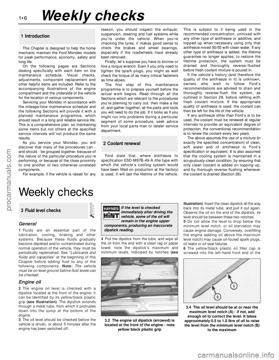
2The engine oil level is checked with a
dipstick located at the front of the engine; it
can be identified by its yellow/black plastic
grip (see illustration). The dipstick extends
through a metal tube, from which it protrudes
down into the sump at the bottom of the
engine.
3The oil level should be checked before the
vehicle is driven, or about 5 minutes after the
engine has been switched off.4Pull the dipstick from the tube, and wipe all
the oil from the end with a clean rag or paper
towel; note the dipstick’s maximum and
minimum levels, indicated by notches (seeillustration). Insert the clean dipstick all the way
back into its metal tube, and pull it out again.
Observe the oil on the end of the dipstick; its
level should be between these two notches.
5Do not allow the level to drop below the
minimum level notch, or oil starvation may
cause engine damage. Conversely, overfilling
the engine (adding oil above the maximum
level notch) may cause oil-fouled spark plugs,
oil leaks or oil seal failures.
6The yellow/black plastic oil filler cap is
screwed into the left-hand front end of the
3 Fluid level checks
3.2 The engine oil dipstick (arrowed) is
located at the front of the engine - note
yellow/black plastic grip
3.4 The oil level should be at or near the
maximum level notch (A) - if not, add
enough oil to correct the level. It takes
approximately 0.5 to 1.0 litre of oil to raise
the level from the minimum level notch (B)
to the maximum
If the level is checked
immediately after driving the
vehicle, some of the oil will
remain in the engine upper
components, producing an inaccurate
dipstick reading.
procarmanuals.com
Page 27 of 279
amperage charger, but don’t use one rated
more than 1/10th the amp/hour rating of the
battery (ie no more than 5 amps, typically).
Rapid boost charges that claim to restore the
power of the battery in one to two hours are
hardest on the battery, and can damage
batteries not in good condition. This type of
charging should only be used in emergency
situations.
14The average time necessary to charge a
battery should be listed in the instructions that
come with the charger. As a general rule, a
trickle charger will charge a battery in 12 to
16 hours.
1Check the seat belts for satisfactory
operation and condition. Inspect the webbing
for fraying and cuts. Check that they retract
smoothly and without binding into their reels.
2Check that the seat belt mounting bolts are
tight, and if necessary tighten them to the
specified torque wrench setting.
General
1The auxiliary drivebelt is of the flat, multi-
ribbed (or “polyvee”) type, and is located on
the right-hand end of the engine. It drives the
alternator, water pump, power steering pump
and (when fitted) the air conditioning
compressor from the engine’s crankshaft
pulley.
2The good condition and proper tension of
the auxiliary drivebelt is critical to the
operation of the engine. Because of their
composition and the high stresses to which
they are subjected, drivebelts stretch anddeteriorate as they get older. They must,
therefore, be regularly inspected.
Check
3With the engine switched off, open and
support the bonnet, then locate the auxiliary
drivebelt on the right-hand end of the engine,
under the engine right-hand mounting
bracket. (Be very careful, and wear protective
gloves to minimise the risk of burning your
hands on hot components, if the engine has
recently been running.) For improved access,
jack up the front right-hand side of the
vehicle, support it securely on an axle stand,
remove the roadwheel, then remove the
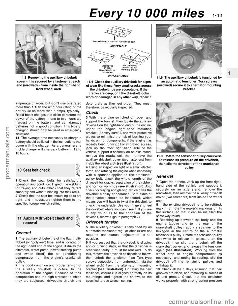
auxiliary drivebelt cover (two fasteners) from
inside the wheel arch (see illustration).
4Using an inspection light or a small electric
torch, and rotating the engine when necessary
with a spanner applied to the crankshaft
pulley bolt, check the whole length of the
drivebelt for cracks, separation of the rubber,
and torn or worn ribs (see illustration). Also
check for fraying and glazing, which gives the
drivebelt a shiny appearance. Both sides of
the drivebelt should be inspected, which
means you will have to twist the drivebelt to
check the underside. Use your fingers to feel
the drivebelt where you can’t see it. If you are
in any doubt as to the condition of the
drivebelt, renew it (go to paragraph 7).
Drivebelt tension
5The auxiliary drivebelt is tensioned by an
automatic tensioner; regular checks are not
required, and manual “adjustment” is not
possible.
6If you suspect that the drivebelt is slipping
and/or running slack, or that the tensioner is
otherwise faulty, it must be renewed. To do
this, remove the drivebelt as described below,
then unbolt the tensioner (two Torx-type
screws accessible from underneath, via the
wheel arch) from the alternator mounting
bracket (see illustration). On fitting the new
tensioner, ensure it is aligned correctly on its
mountings, and tighten the screws to the
specified torque wrench setting.
Renewal
7Open the bonnet. Jack up the front right-
hand side of the vehicle and support it
securely on an axle stand, remove the
roadwheel, then remove the auxiliary drivebelt
cover (two fasteners) from inside the wheel
arch.
8If the existing drivebelt is to be refitted,
mark it, or note the maker’s markings on its
flat surface, so that it can be installed the
same way round.
9Reaching up between the body and the
engine (above and to the rear of the
crankshaft pulley), apply a spanner to the
hexagon in the centre of the automatic
tensioner’s pulley. Rotate the tensioner pulley
clockwise to release its pressure on the
drivebelt, then slip the drivebelt off the
crankshaft pulley, and release the tensioner
again (see illustration). Working from the
wheel arch or engine compartment as
necessary, and noting its routing, slip the
drivebelt off the remaining pulleys and
withdraw it.
10Check all the pulleys, ensuring that their
grooves are clean, and removing all traces of
oil and grease. Check that the tensioner
works properly, with strong spring pressure
11 Auxiliary drivebelt check and
renewal
10 Seat belt check
1•13
1
11.9 Rotate the tensioner pulley clockwise
to release its pressure on the drivebelt,
then slip the drivebelt off the crankshaft
pulley
11.3 Removing the auxiliary drivebelt
cover - it is secured by a fastener at each
end (arrowed) - from inside the right-hand
front wheel arch
11.4 Check the auxiliary drivebelt for signs
of wear like these. Very small cracks across
the drivebelt ribs are acceptable. If the
cracks are deep, or if the drivebelt looks
worn or damaged in any other way, renew it
11.6 The auxiliary drivebelt is tensioned by
an automatic tensioner; Torx screws
(arrowed) secure it to alternator mounting
bracket
Every 10 000 miles
procarmanuals.com
Page 31 of 279
Warning: To avoid personal
injury, never get beneath the
vehicle when it is supported by
only by a jack. The jack provided
with your vehicle is designed solely for
raising the vehicle to remove and refit the
roadwheels. Always use axle stands to
support the vehicle when it becomes
necessary to place your body underneath
the vehicle.
7Being careful not to touch the hot exhaust
components, place the drain pan under the
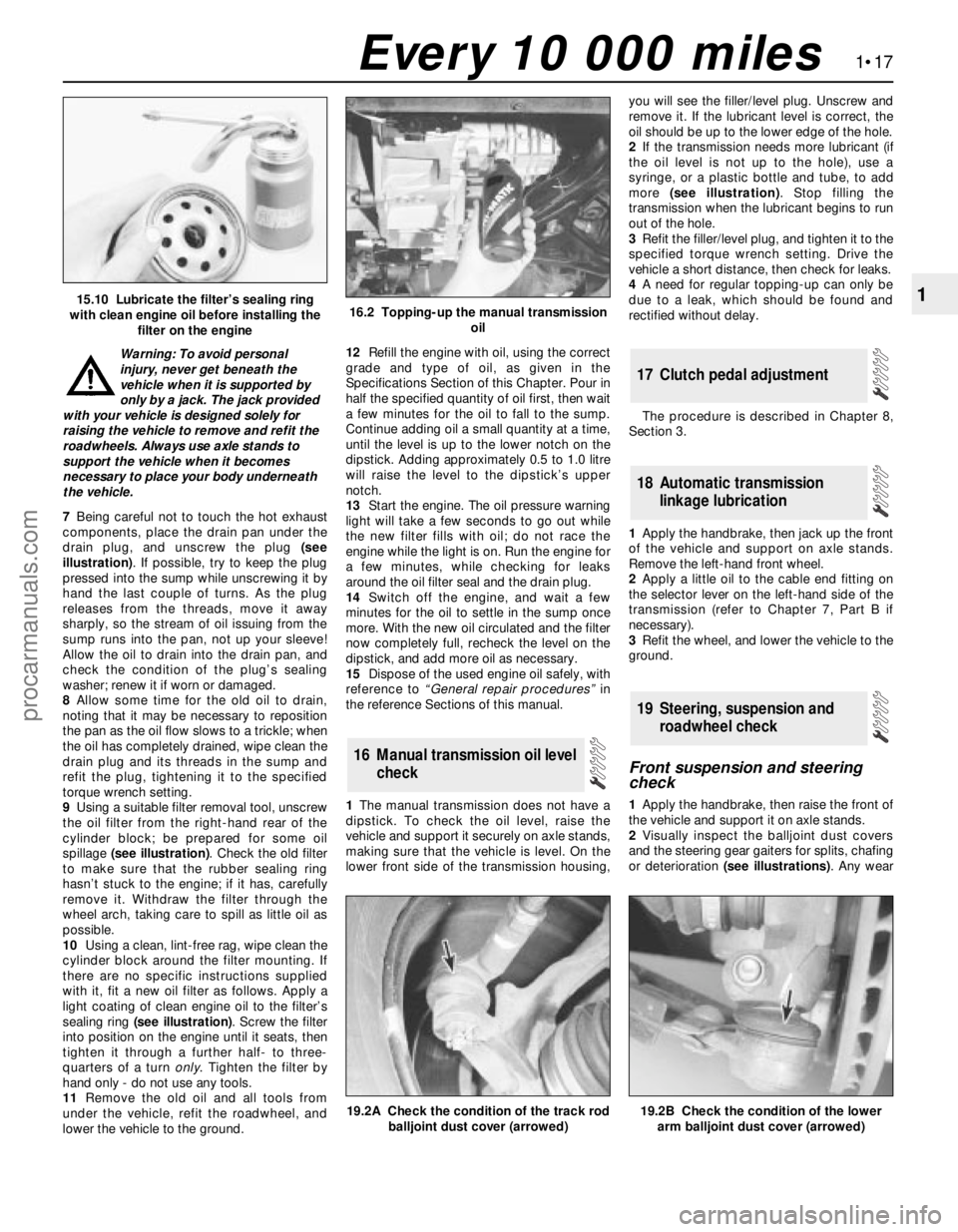
drain plug, and unscrew the plug (see
illustration). If possible, try to keep the plug
pressed into the sump while unscrewing it by
hand the last couple of turns. As the plug
releases from the threads, move it away
sharply, so the stream of oil issuing from the
sump runs into the pan, not up your sleeve!
Allow the oil to drain into the drain pan, and
check the condition of the plug’s sealing
washer; renew it if worn or damaged.
8Allow some time for the old oil to drain,
noting that it may be necessary to reposition
the pan as the oil flow slows to a trickle; when
the oil has completely drained, wipe clean the
drain plug and its threads in the sump and
refit the plug, tightening it to the specified
torque wrench setting.
9Using a suitable filter removal tool, unscrew
the oil filter from the right-hand rear of the
cylinder block; be prepared for some oil
spillage (see illustration). Check the old filter
to make sure that the rubber sealing ring
hasn’t stuck to the engine; if it has, carefully
remove it. Withdraw the filter through the
wheel arch, taking care to spill as little oil as
possible.
10Using a clean, lint-free rag, wipe clean the
cylinder block around the filter mounting. If
there are no specific instructions supplied
with it, fit a new oil filter as follows. Apply a
light coating of clean engine oil to the filter’s
sealing ring (see illustration). Screw the filter
into position on the engine until it seats, then
tighten it through a further half- to three-
quarters of a turn only. Tighten the filter by
hand only - do not use any tools.
11Remove the old oil and all tools from
under the vehicle, refit the roadwheel, and
lower the vehicle to the ground.12Refill the engine with oil, using the correct
grade and type of oil, as given in the
Specifications Section of this Chapter. Pour in
half the specified quantity of oil first, then wait
a few minutes for the oil to fall to the sump.
Continue adding oil a small quantity at a time,
until the level is up to the lower notch on the
dipstick. Adding approximately 0.5 to 1.0 litre
will raise the level to the dipstick’s upper
notch.
13Start the engine. The oil pressure warning
light will take a few seconds to go out while
the new filter fills with oil; do not race the
engine while the light is on. Run the engine for
a few minutes, while checking for leaks
around the oil filter seal and the drain plug.
14Switch off the engine, and wait a few
minutes for the oil to settle in the sump once
more. With the new oil circulated and the filter
now completely full, recheck the level on the
dipstick, and add more oil as necessary.
15Dispose of the used engine oil safely, with
reference to “General repair procedures”in
the reference Sections of this manual.
1The manual transmission does not have a
dipstick. To check the oil level, raise the
vehicle and support it securely on axle stands,
making sure that the vehicle is level. On the
lower front side of the transmission housing,you will see the filler/level plug. Unscrew and
remove it. If the lubricant level is correct, the
oil should be up to the lower edge of the hole.
2If the transmission needs more lubricant (if
the oil level is not up to the hole), use a
syringe, or a plastic bottle and tube, to add
more (see illustration). Stop filling the
transmission when the lubricant begins to run
out of the hole.
3Refit the filler/level plug, and tighten it to the
specified torque wrench setting. Drive the
vehicle a short distance, then check for leaks.
4A need for regular topping-up can only be
due to a leak, which should be found and
rectified without delay.
The procedure is described in Chapter 8,
Section 3.
1Apply the handbrake, then jack up the front
of the vehicle and support on axle stands.
Remove the left-hand front wheel.
2Apply a little oil to the cable end fitting on
the selector lever on the left-hand side of the
transmission (refer to Chapter 7, Part B if
necessary).
3Refit the wheel, and lower the vehicle to the
ground.
Front suspension and steering
check
1Apply the handbrake, then raise the front of
the vehicle and support it on axle stands.
2Visually inspect the balljoint dust covers
and the steering gear gaiters for splits, chafing
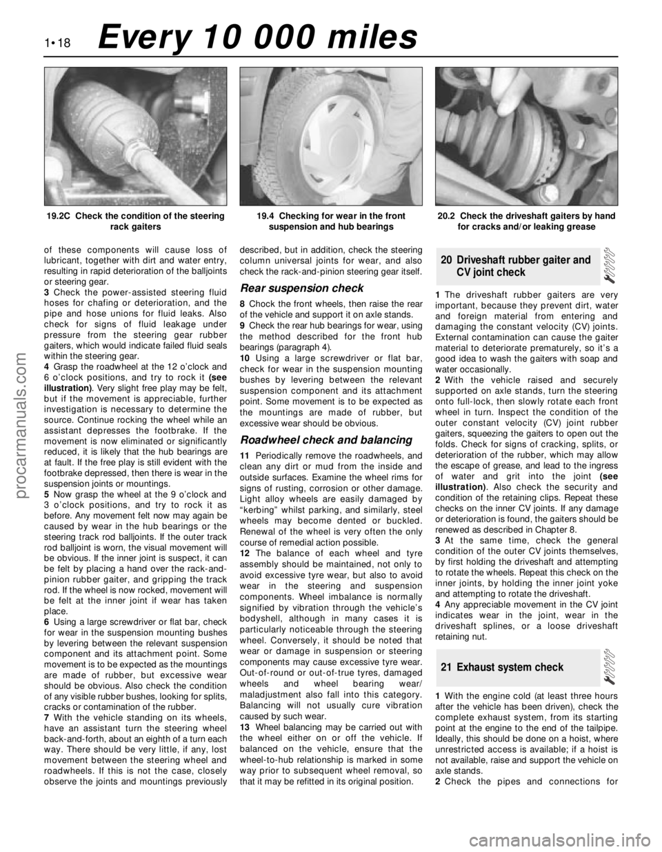
or deterioration (see illustrations). Any wear
19 Steering, suspension and
roadwheel check
18 Automatic transmission
linkage lubrication
17 Clutch pedal adjustment
16 Manual transmission oil level
check
1•17
1
19.2B Check the condition of the lower
arm balljoint dust cover (arrowed)
15.10 Lubricate the filter’s sealing ring
with clean engine oil before installing the
filter on the engine16.2 Topping-up the manual transmission
oil
19.2A Check the condition of the track rod
balljoint dust cover (arrowed)
Every 10 000 miles
procarmanuals.com
Page 32 of 279
of these components will cause loss of
lubricant, together with dirt and water entry,
resulting in rapid deterioration of the balljoints
or steering gear.
3Check the power-assisted steering fluid
hoses for chafing or deterioration, and the
pipe and hose unions for fluid leaks. Also
check for signs of fluid leakage under
pressure from the steering gear rubber
gaiters, which would indicate failed fluid seals
within the steering gear.
4Grasp the roadwheel at the 12 o’clock and
6 o’clock positions, and try to rock it (see
illustration). Very slight free play may be felt,
but if the movement is appreciable, further
investigation is necessary to determine the
source. Continue rocking the wheel while an
assistant depresses the footbrake. If the
movement is now eliminated or significantly
reduced, it is likely that the hub bearings are
at fault. If the free play is still evident with the
footbrake depressed, then there is wear in the
suspension joints or mountings.
5Now grasp the wheel at the 9 o’clock and
3 o’clock positions, and try to rock it as
before. Any movement felt now may again be
caused by wear in the hub bearings or the
steering track rod balljoints. If the outer track
rod balljoint is worn, the visual movement will
be obvious. If the inner joint is suspect, it can
be felt by placing a hand over the rack-and-
pinion rubber gaiter, and gripping the track
rod. If the wheel is now rocked, movement will
be felt at the inner joint if wear has taken
place.
6Using a large screwdriver or flat bar, check
for wear in the suspension mounting bushes
by levering between the relevant suspension
component and its attachment point. Some
movement is to be expected as the mountings
are made of rubber, but excessive wear
should be obvious. Also check the condition
of any visible rubber bushes, looking for splits,
cracks or contamination of the rubber.
7With the vehicle standing on its wheels,
have an assistant turn the steering wheel
back-and-forth, about an eighth of a turn each
way. There should be very little, if any, lost
movement between the steering wheel and
roadwheels. If this is not the case, closely
observe the joints and mountings previouslydescribed, but in addition, check the steering
column universal joints for wear, and also
check the rack-and-pinion steering gear itself.
Rear suspension check
8Chock the front wheels, then raise the rear
of the vehicle and support it on axle stands.
9Check the rear hub bearings for wear, using
the method described for the front hub
bearings (paragraph 4).
10Using a large screwdriver or flat bar,
check for wear in the suspension mounting
bushes by levering between the relevant
suspension component and its attachment
point. Some movement is to be expected as
the mountings are made of rubber, but
excessive wear should be obvious.
Roadwheel check and balancing
11Periodically remove the roadwheels, and
clean any dirt or mud from the inside and
outside surfaces. Examine the wheel rims for
signs of rusting, corrosion or other damage.
Light alloy wheels are easily damaged by
“kerbing” whilst parking, and similarly, steel
wheels may become dented or buckled.
Renewal of the wheel is very often the only
course of remedial action possible.
12The balance of each wheel and tyre
assembly should be maintained, not only to
avoid excessive tyre wear, but also to avoid
wear in the steering and suspension
components. Wheel imbalance is normally
signified by vibration through the vehicle’s
bodyshell, although in many cases it is
particularly noticeable through the steering
wheel. Conversely, it should be noted that
wear or damage in suspension or steering
components may cause excessive tyre wear.
Out-of-round or out-of-true tyres, damaged
wheels and wheel bearing wear/
maladjustment also fall into this category.
Balancing will not usually cure vibration
caused by such wear.
13Wheel balancing may be carried out with
the wheel either on or off the vehicle. If
balanced on the vehicle, ensure that the
wheel-to-hub relationship is marked in some
way prior to subsequent wheel removal, so
that it may be refitted in its original position.1The driveshaft rubber gaiters are very
important, because they prevent dirt, water
and foreign material from entering and
damaging the constant velocity (CV) joints.
External contamination can cause the gaiter
material to deteriorate prematurely, so it’s a
good idea to wash the gaiters with soap and
water occasionally.
2With the vehicle raised and securely
supported on axle stands, turn the steering
onto full-lock, then slowly rotate each front
wheel in turn. Inspect the condition of the
outer constant velocity (CV) joint rubber
gaiters, squeezing the gaiters to open out the
folds. Check for signs of cracking, splits, or
deterioration of the rubber, which may allow
the escape of grease, and lead to the ingress
of water and grit into the joint (see
illustration). Also check the security and
condition of the retaining clips. Repeat these
checks on the inner CV joints. If any damage
or deterioration is found, the gaiters should be
renewed as described in Chapter 8.
3At the same time, check the general
condition of the outer CV joints themselves,
by first holding the driveshaft and attempting
to rotate the wheels. Repeat this check on the
inner joints, by holding the inner joint yoke
and attempting to rotate the driveshaft.
4Any appreciable movement in the CV joint
indicates wear in the joint, wear in the
driveshaft splines, or a loose driveshaft
retaining nut.
1With the engine cold (at least three hours
after the vehicle has been driven), check the
complete exhaust system, from its starting
point at the engine to the end of the tailpipe.
Ideally, this should be done on a hoist, where
unrestricted access is available; if a hoist is
not available, raise and support the vehicle on
axle stands.
2Check the pipes and connections for
21 Exhaust system check
20 Driveshaft rubber gaiter and
CV joint check
1•18
19.2C Check the condition of the steering
rack gaiters19.4 Checking for wear in the front
suspension and hub bearings20.2 Check the driveshaft gaiters by hand
for cracks and/or leaking grease
Every 10 000 miles
procarmanuals.com
Page 34 of 279
brake shoes is not less than the
recommendation given in the Specifications.
14If it is difficult to determine the exact
thickness of the brake shoe linings, or if you
are at all concerned about the condition of the
shoes, then remove the rear drums for a more
comprehensive inspection (refer to Chapter 9)
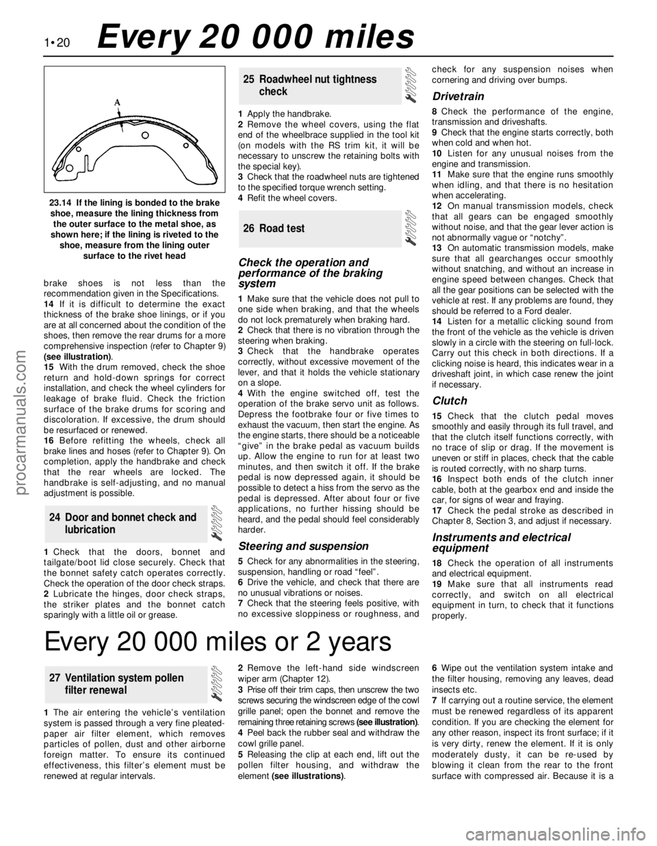
(see illustration).
15With the drum removed, check the shoe
return and hold-down springs for correct
installation, and check the wheel cylinders for
leakage of brake fluid. Check the friction
surface of the brake drums for scoring and
discoloration. If excessive, the drum should
be resurfaced or renewed.
16Before refitting the wheels, check all
brake lines and hoses (refer to Chapter 9). On
completion, apply the handbrake and check
that the rear wheels are locked. The
handbrake is self-adjusting, and no manual
adjustment is possible.
1Check that the doors, bonnet and
tailgate/boot lid close securely. Check that
the bonnet safety catch operates correctly.
Check the operation of the door check straps.
2Lubricate the hinges, door check straps,
the striker plates and the bonnet catch
sparingly with a little oil or grease.1Apply the handbrake.
2Remove the wheel covers, using the flat
end of the wheelbrace supplied in the tool kit
(on models with the RS trim kit, it will be
necessary to unscrew the retaining bolts with
the special key).
3Check that the roadwheel nuts are tightened
to the specified torque wrench setting.
4Refit the wheel covers.
Check the operation and
performance of the braking
system
1Make sure that the vehicle does not pull to
one side when braking, and that the wheels
do not lock prematurely when braking hard.
2Check that there is no vibration through the
steering when braking.
3Check that the handbrake operates
correctly, without excessive movement of the
lever, and that it holds the vehicle stationary
on a slope.
4With the engine switched off, test the
operation of the brake servo unit as follows.
Depress the footbrake four or five times to
exhaust the vacuum, then start the engine. As
the engine starts, there should be a noticeable
“give” in the brake pedal as vacuum builds
up. Allow the engine to run for at least two
minutes, and then switch it off. If the brake
pedal is now depressed again, it should be
possible to detect a hiss from the servo as the
pedal is depressed. After about four or five
applications, no further hissing should be
heard, and the pedal should feel considerably
harder.
Steering and suspension
5Check for any abnormalities in the steering,
suspension, handling or road “feel”.
6Drive the vehicle, and check that there are
no unusual vibrations or noises.
7Check that the steering feels positive, with
no excessive sloppiness or roughness, andcheck for any suspension noises when
cornering and driving over bumps.
Drivetrain
8Check the performance of the engine,
transmission and driveshafts.
9Check that the engine starts correctly, both
when cold and when hot.
10Listen for any unusual noises from the
engine and transmission.
11Make sure that the engine runs smoothly
when idling, and that there is no hesitation
when accelerating.
12On manual transmission models, check
that all gears can be engaged smoothly
without noise, and that the gear lever action is
not abnormally vague or “notchy”.
13On automatic transmission models, make
sure that all gearchanges occur smoothly
without snatching, and without an increase in
engine speed between changes. Check that
all the gear positions can be selected with the
vehicle at rest. If any problems are found, they
should be referred to a Ford dealer.
14Listen for a metallic clicking sound from
the front of the vehicle as the vehicle is driven
slowly in a circle with the steering on full-lock.
Carry out this check in both directions. If a
clicking noise is heard, this indicates wear in a
driveshaft joint, in which case renew the joint
if necessary.
Clutch
15Check that the clutch pedal moves
smoothly and easily through its full travel, and
that the clutch itself functions correctly, with
no trace of slip or drag. If the movement is
uneven or stiff in places, check that the cable
is routed correctly, with no sharp turns.
16Inspect both ends of the clutch inner
cable, both at the gearbox end and inside the
car, for signs of wear and fraying.
17Check the pedal stroke as described in
Chapter 8, Section 3, and adjust if necessary.
Instruments and electrical
equipment
18Check the operation of all instruments
and electrical equipment.
19Make sure that all instruments read
correctly, and switch on all electrical
equipment in turn, to check that it functions
properly.
26 Road test
25 Roadwheel nut tightness
check
24 Door and bonnet check and
lubrication
1•20
23.14 If the lining is bonded to the brake
shoe, measure the lining thickness from
the outer surface to the metal shoe, as
shown here; if the lining is riveted to the
shoe, measure from the lining outer
surface to the rivet head
Every 20 000 miles
Every 20 000 miles or 2 years
1The air entering the vehicle’s ventilation
system is passed through a very fine pleated-
paper air filter element, which removes
particles of pollen, dust and other airborne
foreign matter. To ensure its continued
effectiveness, this filter’s element must be
renewed at regular intervals.2Remove the left-hand side windscreen
wiper arm (Chapter 12).
3Prise off their trim caps, then unscrew the two
screws securing the windscreen edge of the cowl
grille panel; open the bonnet and remove the
remaining three retaining screws (see illustration).
4Peel back the rubber seal and withdraw the
cowl grille panel.
5Releasing the clip at each end, lift out the
pollen filter housing, and withdraw the
element (see illustrations).6Wipe out the ventilation system intake and
the filter housing, removing any leaves, dead
insects etc.
7If carrying out a routine service, the element
must be renewed regardless of its apparent
condition. If you are checking the element for
any other reason, inspect its front surface; if it
is very dirty, renew the element. If it is only
moderately dusty, it can be re-used by
blowing it clean from the rear to the front
surface with compressed air. Because it is a
27 Ventilation system pollen
filter renewal
procarmanuals.com