1993 FORD MONDEO traction control
[x] Cancel search: traction controlPage 4 of 279
0•4Introduction
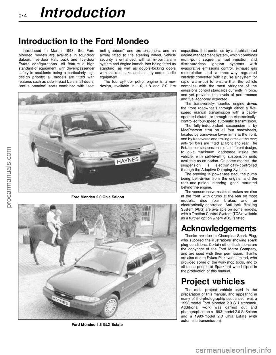
Introduced in March 1993, the Ford
Mondeo models are available in four-door
Saloon, five-door Hatchback and five-door
Estate configurations. All feature a high
standard of equipment, with driver/passenger
safety in accidents being a particularly high
design priority; all models are fitted with
features such as side impact bars in all doors,
“anti-submarine” seats combined with “seatbelt grabbers” and pre-tensioners, and an
airbag fitted to the steering wheel. Vehicle
security is enhanced, with an in-built alarm
system and engine immobiliser being fitted as
standard, as well as double-locking doors
with shielded locks, and security-coded audio
equipment.
The four-cylinder petrol engine is a new
design, available in 1.6, 1.8 and 2.0 litrecapacities. It is controlled by a sophisticated
engine management system, which combines
multi-point sequential fuel injection and
distributorless ignition systems with
evaporative emissions control, exhaust gas
recirculation and a three-way regulated
catalytic converter (with a pulse-air system for
rapid warm-up) to ensure that the vehicle
complies with the most stringent of the
emissions control standards currently in force,
and yet provides the levels of performance
and fuel economy expected.
The transversely-mounted engine drives
the front roadwheels through either a five-
speed manual transmission with a cable-
operated clutch, or through an electronically-
controlled four-speed automatic transmission.
The fully-independent suspension is by
MacPherson strut on all four roadwheels,
located by transverse lower arms at the front,
and by transverse and trailing arms at the rear;
anti-roll bars are fitted at front and rear. The
Estate rear suspension is of a different design,
to give maximum loadspace inside the
vehicle, with self-levelling suspension units
available as an option. On some models, the
suspension is electronically-controlled
through the Adaptive Damping System.
The steering is power-assisted, the pump
being belt-driven from the engine, and the
rack-and-pinion steering gear mounted
behind the engine.
The vacuum servo-assisted brakes are disc
at the front, with drums at the rear on most
models; disc rear brakes and an
electronically-controlled Anti-lock Braking
System (ABS) are available on some models,
with a Traction Control System (TCS) available
as a further option where ABS is fitted.
Acknowledgements
Thanks are due to Champion Spark Plug,
who supplied the illustrations showing spark
plug conditions. Certain other illustrations are
the copyright of the Ford Motor Company,
and are used with their permission. Thanks
are also due to Sykes-Pickavant Limited, who
provided some of the workshop tools, and to
all those people at Sparkford who helped in
the production of this manual.
Project vehicles
The main project vehicle used in the
preparation of this manual, and appearing in
many of the photographic sequences, was a
1993-model Ford Mondeo 2.0 Si Hatchback.
Additional work was carried out and
photographed on a 1993-model 2.0 Si Saloon
and a 1993-model 2.0 Ghia Estate (with
automatic transmission).
Introduction to the Ford Mondeo
Ford Mondeo 2.0 Ghia Saloon
Ford Mondeo 1.8 GLX Estate
procarmanuals.com
Page 99 of 279
Chapter 4 Fuel and exhaust systems
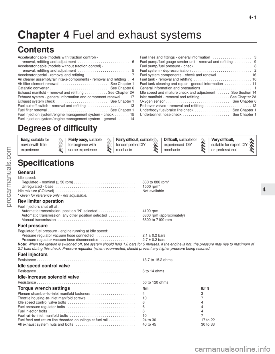
Accelerator cable (models with traction control) -
removal, refitting and adjustment . . . . . . . . . . . . . . . . . . . . . . . . . 6
Accelerator cable (models without traction control) -
removal, refitting and adjustment . . . . . . . . . . . . . . . . . . . . . . . . . 5
Accelerator pedal - removal and refitting . . . . . . . . . . . . . . . . . . . . . 7
Air cleaner assembly/air intake components - removal and refitting . 4
Air filter element renewal . . . . . . . . . . . . . . . . . . . . . . . See Chapter 1
Catalytic converter . . . . . . . . . . . . . . . . . . . . . . . . . . . . See Chapter 6
Exhaust manifold - removal and refitting . . . . . . . . . . . See Chapter 2A
Exhaust system - general information and component renewal . . . . 17
Exhaust system check . . . . . . . . . . . . . . . . . . . . . . . . . See Chapter 1
Fuel cut-off switch - removal and refitting . . . . . . . . . . . . . . . . . . . . 13
Fuel filter renewal . . . . . . . . . . . . . . . . . . . . . . . . . . . . . See Chapter 1
Fuel injection system/engine management system - check . . . . . . . 15
Fuel injection system/engine management system - general . . . . . 14Fuel lines and fittings - general information . . . . . . . . . . . . . . . . . . . 3
Fuel pump/fuel gauge sender unit - removal and refitting . . . . . . . . 9
Fuel pump/fuel pressure - check . . . . . . . . . . . . . . . . . . . . . . . . . . . 8
Fuel system - depressurisation . . . . . . . . . . . . . . . . . . . . . . . . . . . . . 2
Fuel system components - check and renewal . . . . . . . . . . . . . . . . 16
Fuel tank - removal and refitting . . . . . . . . . . . . . . . . . . . . . . . . . . . . 10
Fuel tank cleaning and repair - general information . . . . . . . . . . . . . 11
General information and precautions . . . . . . . . . . . . . . . . . . . . . . . . 1
Idle speed and mixture check and adjustment . . . . . . See Section 14
Inlet manifold - removal and refitting . . . . . . . . . . . . . . See Chapter 2A
Oxygen sensor . . . . . . . . . . . . . . . . . . . . . . . . . . . . . . . See Chapter 6
Roll-over valves - removal and refitting . . . . . . . . . . . . . . . . . . . . . . . 12
Underbody fuel/brake line check . . . . . . . . . . . . . . . . . See Chapter 1
Underbonnet hose check . . . . . . . . . . . . . . . . . . . . . . . See Chapter 1
General
Idle speed:
Regulated - nominal (± 50 rpm) . . . . . . . . . . . . . . . . . . . . . . . . . . . . . . 830 to 880 rpm*
Unregulated - base . . . . . . . . . . . . . . . . . . . . . . . . . . . . . . . . . . . . . . . 1500 rpm*
Idle mixture (CO level) . . . . . . . . . . . . . . . . . . . . . . . . . . . . . . . . . . . . . . . Not available
* Given for reference only - not adjustable.
Rev limiter operation
Fuel injectors shut off at:
Automatic transmission, position “N” selected . . . . . . . . . . . . . . . . . . 4100 rpm
Automatic transmission, any other position selected . . . . . . . . . . . . . 6800 rpm (approximately)
Manual transmission . . . . . . . . . . . . . . . . . . . . . . . . . . . . . . . . . . . . . . 6800 to 7100 rpm
Fuel pressure
Regulated fuel pressure - engine running at idle speed:
Pressure regulator vacuum hose connected . . . . . . . . . . . . . . . . . . . 2.1 ± 0.2 bars
Pressure regulator vacuum hose disconnected . . . . . . . . . . . . . . . . . 2.7 ± 0.2 bars
Note:When the ignition is switched off, the system should hold 1.8 bars for 5 minutes. If the engine is hot, the pressure may rise to maximum of
2.7 bars during this check. Pressure regulator (when reconnected) should prevent any higher pressure being reached.
Fuel injectors
Resistance . . . . . . . . . . . . . . . . . . . . . . . . . . . . . . . . . . . . . . . . . . . . . . . . 13.7 to 15.2 ohms
Idle speed control valve
Resistance . . . . . . . . . . . . . . . . . . . . . . . . . . . . . . . . . . . . . . . . . . . . . . . . 6 to 14 ohms
Idle-increase solenoid valve
Resistance . . . . . . . . . . . . . . . . . . . . . . . . . . . . . . . . . . . . . . . . . . . . . . . . 50 to 120 ohms
Torque wrench settingsNm lbf ft
Plenum chamber-to-inlet manifold fasteners . . . . . . . . . . . . . . . . . . . . . 4 3
Throttle housing-to-inlet manifold screws . . . . . . . . . . . . . . . . . . . . . . . 10 7
Idle speed control valve bolts . . . . . . . . . . . . . . . . . . . . . . . . . . . . . . . . . 6 4
Fuel pressure regulator bolts . . . . . . . . . . . . . . . . . . . . . . . . . . . . . . . . . 6 4
Fuel injector bolts . . . . . . . . . . . . . . . . . . . . . . . . . . . . . . . . . . . . . . . . . . 6 4
Fuel rail-to-inlet manifold bolts . . . . . . . . . . . . . . . . . . . . . . . . . . . . . . . . 10 7
Fuel feed and return line threaded couplings at fuel rail . . . . . . . . . . . . . 24 to 30 17 to 22
All exhaust system nuts and bolts . . . . . . . . . . . . . . . . . . . . . . . . . . . . . 40 to 45 30 to 33
4•1
Easy,suitable for
novice with little
experienceFairly easy,suitable
for beginner with
some experienceFairly difficult,suitable
for competent DIY
mechanicDifficult,suitable for
experienced DIY
mechanicVery difficult,
suitable for expert DIY
or professional
Degrees of difficulty
Specifications Contents
4
procarmanuals.com
Page 102 of 279
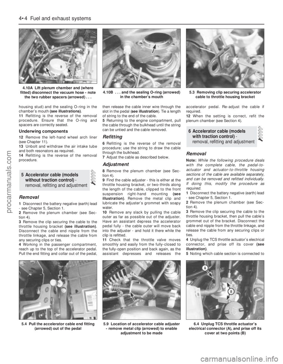
housing stud) and the sealing O-ring in the
chamber’s mouth (see illustrations).
11Refitting is the reverse of the removal
procedure. Ensure that the O-ring and
spacers are correctly seated.
Underwing components
12Remove the left-hand wheel arch liner
(see Chapter 11).
13Unbolt and withdraw the air intake tube
and both resonators as required.
14Refitting is the reverse of the removal
procedure.
Removal
1Disconnect the battery negative (earth) lead
- see Chapter 5, Section 1.
2Remove the plenum chamber (see Sec-
tion 4).
3Remove the clip securing the cable to the
throttle housing bracket (see illustration).
Disconnect the cable end nipple from the
throttle linkage, and release the cable from
any securing clips or ties.
4Working in the passenger compartment,
reach up to the top of the accelerator pedal.
Pull the end fitting and collar out of the pedal,then release the cable inner wire through the
slot in the pedal (see illustration). Tie a length
of string to the end of the cable.
5Returning to the engine compartment, pull
the cable through the bulkhead until the string
can be untied and the cable removed.
Refitting
6Refitting is the reverse of the removal
procedure; use the string to draw the cable
through the bulkhead.
7Adjust the cable as described below.
Adjustment
8Remove the plenum chamber (see Sec-
tion 4).
9Find the cable adjuster - this is either at the
throttle housing bracket, or two-thirds along
the length of the cable, clipped to the front
suspension right-hand mounting (see
illustration). Remove the metal clip and
lubricate the adjuster’s grommet with soapy
water.
10Remove any slack by pulling the cable
outer as far as possible out of the adjuster.
Have an assistant depress the accelerator
pedal fully - the cable outer will move back
into the adjuster - and hold it there while the
clip is refitted.
11Check that the throttle valve moves
smoothly and easily from the fully-closed to
the fully-open position and back again, as the
assistant depresses and releases theaccelerator pedal. Re-adjust the cable if
required.
12When the setting is correct, refit the
plenum chamber (see Section 4).
Removal
Note:While the following procedure deals
with the complete cable, the pedal-to-
actuator and actuator-to-throttle housing
sections of the cable are available separately,
and can be removed and refitted individually.
If doing this, modify the procedure as
required.
1Disconnect the battery negative (earth) lead
- see Chapter 5, Section 1.
2Remove the plenum chamber (see Sec-
tion 4).
3Remove the clip securing the cable to the
throttle housing bracket, then pull the cable’s
grommet out of the bracket. Disconnect the
cable end nipple from the throttle linkage, and
release the cable from any securing clips or
ties.
4Unplug the TCS throttle actuator’s electrical
connector, and prise off its cover (see
illustration).
5Noting which cable section is connected to
6 Accelerator cable (models
with traction control)-
removal, refitting and adjustment
5 Accelerator cable (models
without traction control) -
removal, refitting and adjustment
4•4 Fuel and exhaust systems
4.10A Lift plenum chamber and (where
fitted) disconnect the vacuum hose - note
the two rubber spacers (arrowed) . . .4.10B . . . and the sealing O-ring (arrowed)
in the chamber’s mouth5.3 Removing clip securing accelerator
cable to throttle housing bracket
5.4 Pull the accelerator cable end fitting
(arrowed) out of the pedal5.9 Location of accelerator cable adjuster
- remove metal clip (arrowed) to enable
adjustment to be made6.4 Unplug TCS throttle actuator’s
electrical connector (A), and prise off its
cover at two points (B)
procarmanuals.com
Page 120 of 279
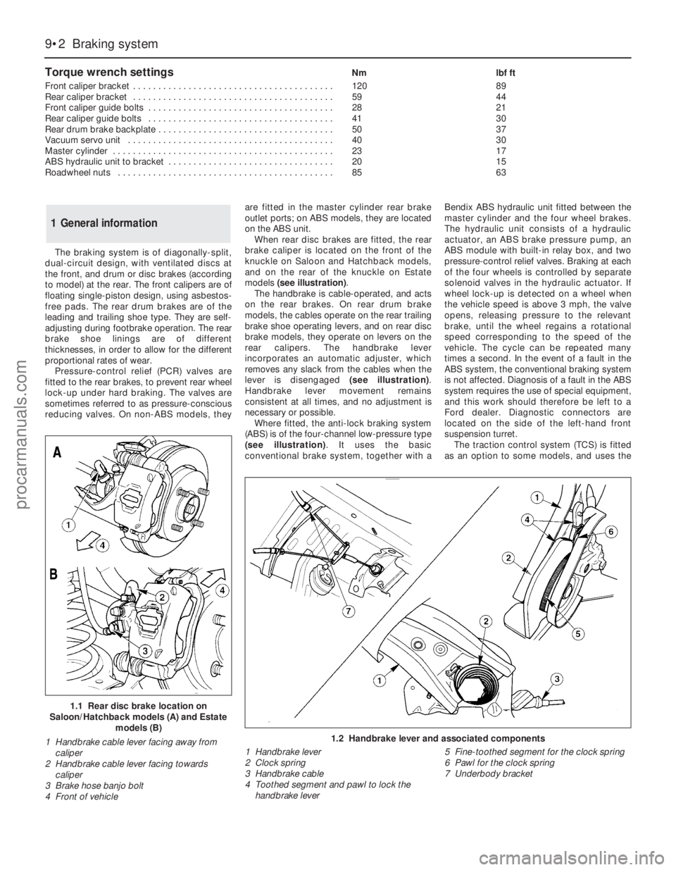
Torque wrench settingsNm lbf ft
Front caliper bracket . . . . . . . . . . . . . . . . . . . . . . . . . . . . . . . . . . . . . . . . 120 89
Rear caliper bracket . . . . . . . . . . . . . . . . . . . . . . . . . . . . . . . . . . . . . . . . 59 44
Front caliper guide bolts . . . . . . . . . . . . . . . . . . . . . . . . . . . . . . . . . . . . . 28 21
Rear caliper guide bolts . . . . . . . . . . . . . . . . . . . . . . . . . . . . . . . . . . . . . 41 30
Rear drum brake backplate . . . . . . . . . . . . . . . . . . . . . . . . . . . . . . . . . . . 50 37
Vacuum servo unit . . . . . . . . . . . . . . . . . . . . . . . . . . . . . . . . . . . . . . . . . 40 30
Master cylinder . . . . . . . . . . . . . . . . . . . . . . . . . . . . . . . . . . . . . . . . . . . . 23 17
ABS hydraulic unit to bracket . . . . . . . . . . . . . . . . . . . . . . . . . . . . . . . . . 20 15
Roadwheel nuts . . . . . . . . . . . . . . . . . . . . . . . . . . . . . . . . . . . . . . . . . . . 85 63
9•2 Braking system
1.2 Handbrake lever and associated components
1 Handbrake lever
2 Clock spring
3 Handbrake cable
4 Toothed segment and pawl to lock the
handbrake lever5 Fine-toothed segment for the clock spring
6 Pawl for the clock spring
7 Underbody bracket
The braking system is of diagonally-split,
dual-circuit design, with ventilated discs at
the front, and drum or disc brakes (according
to model) at the rear. The front calipers are of
floating single-piston design, using asbestos-
free pads. The rear drum brakes are of the
leading and trailing shoe type. They are self-
adjusting during footbrake operation. The rear
brake shoe linings are of different
thicknesses, in order to allow for the different
proportional rates of wear.
Pressure-control relief (PCR) valves are
fitted to the rear brakes, to prevent rear wheel
lock-up under hard braking. The valves are
sometimes referred to as pressure-conscious
reducing valves. On non-ABS models, theyare fitted in the master cylinder rear brake
outlet ports; on ABS models, they are located
on the ABS unit.
When rear disc brakes are fitted, the rear
brake caliper is located on the front of the
knuckle on Saloon and Hatchback models,
and on the rear of the knuckle on Estate
models (see illustration).
The handbrake is cable-operated, and acts
on the rear brakes. On rear drum brake
models, the cables operate on the rear trailing
brake shoe operating levers, and on rear disc
brake models, they operate on levers on the
rear calipers. The handbrake lever
incorporates an automatic adjuster, which
removes any slack from the cables when the
lever is disengaged (see illustration).
Handbrake lever movement remains
consistent at all times, and no adjustment is
necessary or possible.
Where fitted, the anti-lock braking system
(ABS) is of the four-channel low-pressure type
(see illustration). It uses the basic
conventional brake system, together with aBendix ABS hydraulic unit fitted between the
master cylinder and the four wheel brakes.
The hydraulic unit consists of a hydraulic
actuator, an ABS brake pressure pump, an
ABS module with built-in relay box, and two
pressure-control relief valves. Braking at each
of the four wheels is controlled by separate
solenoid valves in the hydraulic actuator. If
wheel lock-up is detected on a wheel when
the vehicle speed is above 3 mph, the valve
opens, releasing pressure to the relevant
brake, until the wheel regains a rotational
speed corresponding to the speed of the
vehicle. The cycle can be repeated many
times a second. In the event of a fault in the
ABS system, the conventional braking system
is not affected. Diagnosis of a fault in the ABS
system requires the use of special equipment,
and this work should therefore be left to a
Ford dealer. Diagnostic connectors are
located on the side of the left-hand front
suspension turret.
The traction control system (TCS) is fitted
as an option to some models, and uses the
1 General information
1.1 Rear disc brake location on
Saloon/Hatchback models (A) and Estate
models (B)
1 Handbrake cable lever facing away from
caliper
2 Handbrake cable lever facing towards
caliper
3 Brake hose banjo bolt
4 Front of vehicle
procarmanuals.com
Page 121 of 279
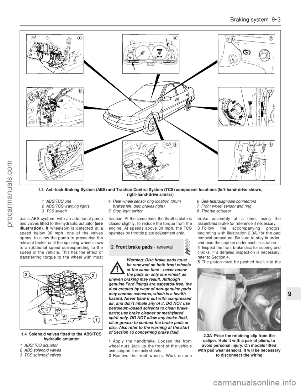
basic ABS system, with an additional pump
and valves fitted to the hydraulic actuator (see
illustration). If wheelspin is detected at a
speed below 30 mph, one of the valves
opens, to allow the pump to pressurise the
relevant brake, until the spinning wheel slows
to a rotational speed corresponding to the
speed of the vehicle. This has the effect of
transferring torque to the wheel with mosttraction. At the same time, the throttle plate is
closed slightly, to reduce the torque from the
engine. At speeds above 30 mph, the TCS
operates by throttle plate adjustment only.
Warning: Disc brake pads must
be renewed on both front wheels
at the same time - never renew
the pads on only one wheel, as
uneven braking may result. Although
genuine Ford linings are asbestos-free, the
dust created by wear of non-genuine pads
may contain asbestos, which is a health
hazard. Never blow it out with compressed
air, and don’t inhale any of it. DO NOT use
petroleum-based solvents to clean brake
parts; use brake cleaner or methylated
spirit only. DO NOT allow any brake fluid,
oil or grease to contact the brake pads or
disc. Also refer to the warning at the start
of Section 15 concerning brake fluid.
1Apply the handbrake. Loosen the front
wheel nuts, jack up the front of the vehicle
and support it on axle stands.
2Remove the front wheels. Work on onebrake assembly at a time, using the
assembled brake for reference if necessary.
3Follow the accompanying photos,
beginning with illustration 2.3A, for the pad
removal procedure. Be sure to stay in order,
and read the caption under each illustration.
4Inspect the front brake disc for scoring and
cracks. If a detailed inspection is necessary,
refer to Section 4.
5The piston must be pushed back into the
2 Front brake pads - renewal
Braking system 9•3
9
1.4 Solenoid valves fitted to the ABS/TCS
hydraulic actuator
1 ABS/TCS actuator
2 ABS solenoid valves
3 TCS solenoid valves
1.3 Anti-lock Braking System (ABS) and Traction Control System (TCS) component locations (left-hand-drive shown,
right-hand-drive similar)
1 ABS/TCS unit
2 ABS/TCS warning lights
3 TCS switch4 Rear wheel sensor ring location (drum
brakes left, disc brakes right)
5 Stop-light switch6 Self-test/diagnosis connectors
7 Front wheel sensor and ring
8 Throttle actuator
2.3A Prise the retaining clip from the
caliper. Hold it with a pair of pliers, to
avoid personal injury. On models fitted
with pad wear sensors, it will be necessary
to disconnect the wiring
procarmanuals.com
Page 208 of 279
Main light, auxiliary foglight and rear
foglight combination switch
Note:From July 1994 a rvised main light
switch was introduced; this was fitted as
standard in production. If the revised switch is
to be fitted to a pre-July 1994 model, an
adapter lead will also be required to prevent
electrical damage ocurring. Refer to your Ford
dealer for further information
9Disconnect the battery negative (earth) lead
(refer to Chapter 5, Section 1).
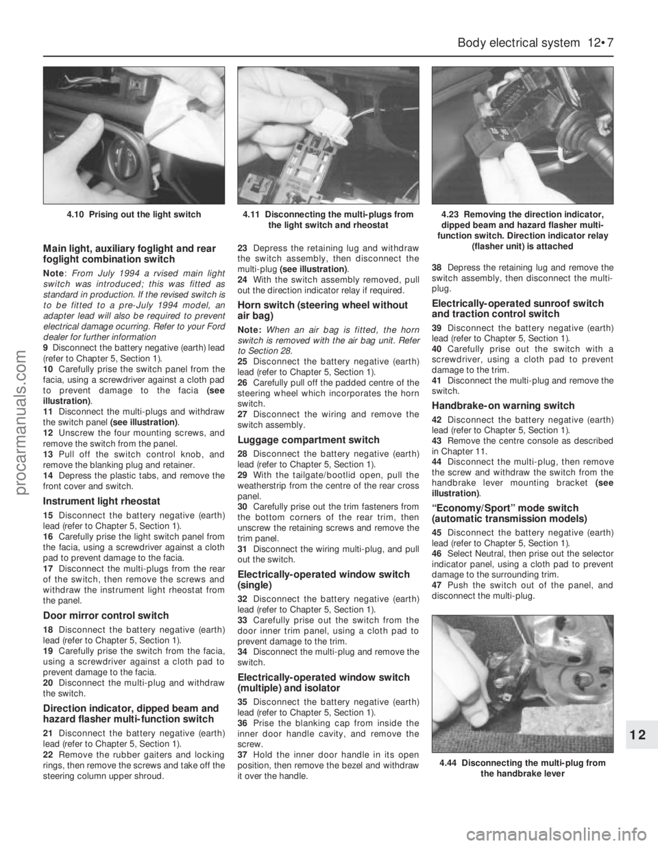
10Carefully prise the switch panel from the
facia, using a screwdriver against a cloth pad
to prevent damage to the facia (see
illustration).
11Disconnect the multi-plugs and withdraw
the switch panel (see illustration).
12Unscrew the four mounting screws, and
remove the switch from the panel.
13Pull off the switch control knob, and
remove the blanking plug and retainer.
14Depress the plastic tabs, and remove the
front cover and switch.
Instrument light rheostat
15Disconnect the battery negative (earth)
lead (refer to Chapter 5, Section 1).
16Carefully prise the light switch panel from
the facia, using a screwdriver against a cloth
pad to prevent damage to the facia.
17Disconnect the multi-plugs from the rear
of the switch, then remove the screws and
withdraw the instrument light rheostat from
the panel.
Door mirror control switch
18Disconnect the battery negative (earth)
lead (refer to Chapter 5, Section 1).
19Carefully prise the switch from the facia,
using a screwdriver against a cloth pad to
prevent damage to the facia.
20Disconnect the multi-plug and withdraw
the switch.
Direction indicator, dipped beam and
hazard flasher multi-function switch
21Disconnect the battery negative (earth)
lead (refer to Chapter 5, Section 1).
22Remove the rubber gaiters and locking
rings, then remove the screws and take off the
steering column upper shroud.23Depress the retaining lug and withdraw
the switch assembly, then disconnect the
multi-plug (see illustration).
24With the switch assembly removed, pull
out the direction indicator relay if required.
Horn switch (steering wheel without
air bag)
Note:When an air bag is fitted, the horn
switch is removed with the air bag unit. Refer
to Section 28.
25Disconnect the battery negative (earth)
lead (refer to Chapter 5, Section 1).
26Carefully pull off the padded centre of the
steering wheel which incorporates the horn
switch.
27Disconnect the wiring and remove the
switch assembly.
Luggage compartment switch
28Disconnect the battery negative (earth)
lead (refer to Chapter 5, Section 1).
29With the tailgate/bootlid open, pull the
weatherstrip from the centre of the rear cross
panel.
30Carefully prise out the trim fasteners from
the bottom corners of the rear trim, then
unscrew the retaining screws and remove the
trim panel.
31Disconnect the wiring multi-plug, and pull
out the switch.
Electrically-operated window switch
(single)
32Disconnect the battery negative (earth)
lead (refer to Chapter 5, Section 1).
33Carefully prise out the switch from the
door inner trim panel, using a cloth pad to
prevent damage to the trim.
34Disconnect the multi-plug and remove the
switch.
Electrically-operated window switch
(multiple) and isolator
35Disconnect the battery negative (earth)
lead (refer to Chapter 5, Section 1).
36Prise the blanking cap from inside the
inner door handle cavity, and remove the
screw.
37Hold the inner door handle in its open
position, then remove the bezel and withdraw
it over the handle.38Depress the retaining lug and remove the
switch assembly, then disconnect the multi-
plug.
Electrically-operated sunroof switch
and traction control switch
39Disconnect the battery negative (earth)
lead (refer to Chapter 5, Section 1).
40Carefully prise out the switch with a
screwdriver, using a cloth pad to prevent
damage to the trim.
41Disconnect the multi-plug and remove the
switch.
Handbrake-on warning switch
42Disconnect the battery negative (earth)
lead (refer to Chapter 5, Section 1).
43Remove the centre console as described
in Chapter 11.
44Disconnect the multi-plug, then remove
the screw and withdraw the switch from the
handbrake lever mounting bracket (see
illustration).
“Economy/Sport” mode switch
(automatic transmission models)
45Disconnect the battery negative (earth)
lead (refer to Chapter 5, Section 1).
46Select Neutral, then prise out the selector
indicator panel, using a cloth pad to prevent
damage to the surrounding trim.
47Push the switch out of the panel, and
disconnect the multi-plug.
Body electrical system 12•7
12
4.44 Disconnecting the multi-plug from
the handbrake lever
4.10 Prising out the light switch4.11 Disconnecting the multi-plugs from
the light switch and rheostat4.23 Removing the direction indicator,
dipped beam and hazard flasher multi-
function switch. Direction indicator relay
(flasher unit) is attached
procarmanuals.com
Page 220 of 279
4The system module is located on a bracket
beneath the right-hand side of the facia. The
set and reset switches are located in a
housing by the lock barrel holder in the doors,
tailgate or bootlid.
5To allow temporary opening of the tailgate
or bootlid, an inhibit switch is fitted to the lock
barrel. This suppresses the alarm system until
the tailgate or bootlid is closed again.
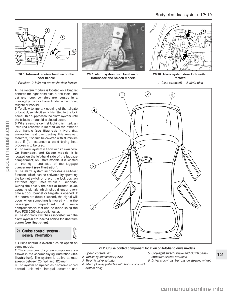
6Where remote central locking is fitted, an
infra-red receiver is located on the exterior
door handle (see illustration). Note that
excessive heat can destroy this receiver;
therefore, it should be covered with aluminium
tape if (for instance) a paint-drying heat
process is to be used.
7The alarm system is fitted with its own horn.
On Hatchback and Saloon models, it is
located on the left-hand side of the luggage
compartment; on Estate models, it is located
on the right-hand side of the luggage
compartment (see illustration).
8The alarm system incorporates a self-test
function, which can be activated by operating
the bonnet switch or one of the lock position
switches eight times within 10 seconds.
During the check, the horn or buzzer issues
acoustic signals which should occur every
time a door, bonnet or tailgate is opened. If
the doors are double-locked, the signal will
occur when something is moved within the
passenger compartment. A more
comprehensive test can be made using the
Ford FDS 2000 diagnostic tester.
9The door lock switches associated with the
alarm system are located behind the door trim
panels (see illustration).
1Cruise control is available as an option on
some models.
2The cruise control system components are
shown in the accompanying illustration (see
illustration). The system is active at road
speeds between 25 mph and 125 mph.
3The system comprises an electronic speed
control unit with integral actuator and
21 Cruise control system -
general information
Body electrical system 12•19
12
21.2 Cruise control component location on left-hand drive models
1 Speed control unit
2 Vehicle speed sensor (VSS)
3 Throttle valve actuator
4 Interrupt relay (vehicles with traction control
system only)5 Stop-light switch, brake and clutch pedal-
operated disable switches
6 Driver’s controls (buttons on steering wheel)
20.6 Infra-red receiver location on the
door handle
1 Receiver 2 Infra-red eye on the door handle20.7 Alarm system horn location on
Hatchback and Saloon models20.10 Alarm system door lock switch
removal
1 Clips (arrowed) 2 Multi-plug
procarmanuals.com
Page 254 of 279
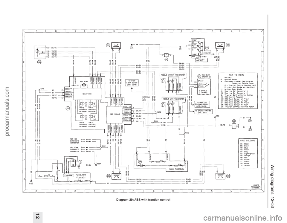
Wiring diagrams 12•53
12
Diagram 29: ABS with traction control
procarmanuals.com