1993 FORD MONDEO four wheel drive
[x] Cancel search: four wheel drivePage 1 of 279
Ford Mondeo
Service and Repair Manual
Jeremy Churchill and A K Legg LAE MIMI
Models covered
All Ford Mondeo models with four-cylinder petrol engines,
including special/limited editions
1597 cc, 1796 cc and 1988 cc
Does not cover Diesel or V6 engines, or four-wheel-drive models
© Haynes Publishing 1996
A book in the Haynes Service and Repair Manual Series
All rights reserved. No part of this book may be reproduced or transmitted
in any form or by any means, electronic or mechanical, including
photocopying, recording or by any information storage or retrieval system,
without permission in writing from the copyright holder.
ISBN1 85960 167 7
British Library Cataloguing in Publication Data
A catalogue record for this book is available from the British Library.Printed by J H Haynes & Co. Ltd, Sparkford, Nr Yeovil,
Somerset BA22 7JJ
Haynes Publishing
Sparkford, Nr Yeovil, Somerset BA22 7JJ, England
Haynes North America, Inc
861 Lawrence Drive, Newbury Park, California 91320, USA
Editions Haynes S.A.
147/149, rue Saint Honoré, 75001 PARIS, France
(1923-304-10X3)
procarmanuals.com
Page 4 of 279
0•4Introduction
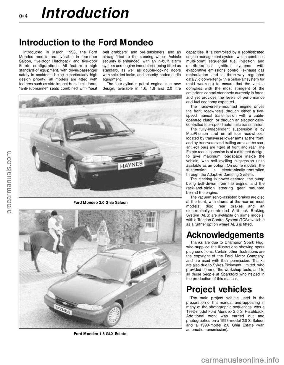
Introduced in March 1993, the Ford
Mondeo models are available in four-door
Saloon, five-door Hatchback and five-door
Estate configurations. All feature a high
standard of equipment, with driver/passenger
safety in accidents being a particularly high
design priority; all models are fitted with
features such as side impact bars in all doors,
“anti-submarine” seats combined with “seatbelt grabbers” and pre-tensioners, and an
airbag fitted to the steering wheel. Vehicle
security is enhanced, with an in-built alarm
system and engine immobiliser being fitted as
standard, as well as double-locking doors
with shielded locks, and security-coded audio
equipment.
The four-cylinder petrol engine is a new
design, available in 1.6, 1.8 and 2.0 litrecapacities. It is controlled by a sophisticated
engine management system, which combines
multi-point sequential fuel injection and
distributorless ignition systems with
evaporative emissions control, exhaust gas
recirculation and a three-way regulated
catalytic converter (with a pulse-air system for
rapid warm-up) to ensure that the vehicle
complies with the most stringent of the
emissions control standards currently in force,
and yet provides the levels of performance
and fuel economy expected.
The transversely-mounted engine drives
the front roadwheels through either a five-
speed manual transmission with a cable-
operated clutch, or through an electronically-
controlled four-speed automatic transmission.
The fully-independent suspension is by
MacPherson strut on all four roadwheels,
located by transverse lower arms at the front,
and by transverse and trailing arms at the rear;
anti-roll bars are fitted at front and rear. The
Estate rear suspension is of a different design,
to give maximum loadspace inside the
vehicle, with self-levelling suspension units
available as an option. On some models, the
suspension is electronically-controlled
through the Adaptive Damping System.
The steering is power-assisted, the pump
being belt-driven from the engine, and the
rack-and-pinion steering gear mounted
behind the engine.
The vacuum servo-assisted brakes are disc
at the front, with drums at the rear on most
models; disc rear brakes and an
electronically-controlled Anti-lock Braking
System (ABS) are available on some models,
with a Traction Control System (TCS) available
as a further option where ABS is fitted.
Acknowledgements
Thanks are due to Champion Spark Plug,
who supplied the illustrations showing spark
plug conditions. Certain other illustrations are
the copyright of the Ford Motor Company,
and are used with their permission. Thanks
are also due to Sykes-Pickavant Limited, who
provided some of the workshop tools, and to
all those people at Sparkford who helped in
the production of this manual.
Project vehicles
The main project vehicle used in the
preparation of this manual, and appearing in
many of the photographic sequences, was a
1993-model Ford Mondeo 2.0 Si Hatchback.
Additional work was carried out and
photographed on a 1993-model 2.0 Si Saloon
and a 1993-model 2.0 Ghia Estate (with
automatic transmission).
Introduction to the Ford Mondeo
Ford Mondeo 2.0 Ghia Saloon
Ford Mondeo 1.8 GLX Estate
procarmanuals.com
Page 7 of 279
0•7
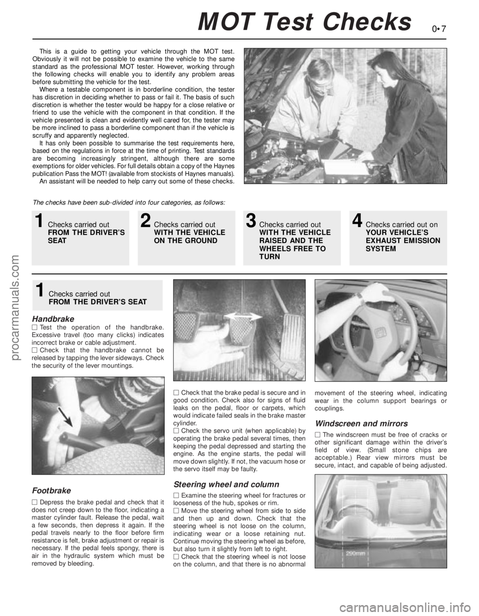
This is a guide to getting your vehicle through the MOT test.
Obviously it will not be possible to examine the vehicle to the same
standard as the professional MOT tester. However, working through
the following checks will enable you to identify any problem areas
before submitting the vehicle for the test.
Where a testable component is in borderline condition, the tester
has discretion in deciding whether to pass or fail it. The basis of such
discretion is whether the tester would be happy for a close relative or
friend to use the vehicle with the component in that condition. If the
vehicle presented is clean and evidently well cared for, the tester may
be more inclined to pass a borderline component than if the vehicle is
scruffy and apparently neglected.
It has only been possible to summarise the test requirements here,
based on the regulations in force at the time of printing. Test standards
are becoming increasingly stringent, although there are some
exemptions for older vehicles. For full details obtain a copy of the Haynes
publication Pass the MOT! (available from stockists of Haynes manuals).
An assistant will be needed to help carry out some of these checks.
The checks have been sub-divided into four categories, as follows:
HandbrakeMTest the operation of the handbrake.
Excessive travel (too many clicks) indicates
incorrect brake or cable adjustment.
MCheck that the handbrake cannot be
released by tapping the lever sideways. Check
the security of the lever mountings.
Footbrake
MDepress the brake pedal and check that it
does not creep down to the floor, indicating a
master cylinder fault. Release the pedal, wait
a few seconds, then depress it again. If the
pedal travels nearly to the floor before firm
resistance is felt, brake adjustment or repair is
necessary. If the pedal feels spongy, there is
air in the hydraulic system which must be
removed by bleeding.MCheck that the brake pedal is secure and in
good condition. Check also for signs of fluid
leaks on the pedal, floor or carpets, which
would indicate failed seals in the brake master
cylinder.
MCheck the servo unit (when applicable) by
operating the brake pedal several times, then
keeping the pedal depressed and starting the
engine. As the engine starts, the pedal will
move down slightly. If not, the vacuum hose or
the servo itself may be faulty.
Steering wheel and column
MExamine the steering wheel for fractures or
looseness of the hub, spokes or rim.
MMove the steering wheel from side to side
and then up and down. Check that the
steering wheel is not loose on the column,
indicating wear or a loose retaining nut.
Continue moving the steering wheel as before,
but also turn it slightly from left to right.
MCheck that the steering wheel is not loose
on the column, and that there is no abnormalmovement of the steering wheel, indicating
wear in the column support bearings or
couplings.
Windscreen and mirrors
MThe windscreen must be free of cracks or
other significant damage within the driver’s
field of view. (Small stone chips are
acceptable.) Rear view mirrors must be
secure, intact, and capable of being adjusted.
1Checks carried out
FROM THE DRIVER’S SEAT
MOT Test Checks
1Checks carried out
FROM THE DRIVER’S
SEAT2Checks carried out
WITH THE VEHICLE
ON THE GROUND3Checks carried out
WITH THE VEHICLE
RAISED AND THE
WHEELS FREE TO
TURN4Checks carried out on
YOUR VEHICLE’S
EXHAUST EMISSION
SYSTEM
procarmanuals.com
Page 17 of 279
Ford Mondeo maintenance schedule
1•3
1
Maintenance schedule
The manufacturer’s recommended maintenance schedule for these
vehicles is as described below - note that the schedule starts from the
vehicle’s date of registration. These are the minimum maintenance
intervals recommended by the factory for Mondeos driven daily, but
subjected only to “normal” use. If you wish to keep your vehicle in
peak condition at all times, you may wish to perform some of these
procedures even more often. Because frequent maintenance
enhances the efficiency, performance and resale value of your vehicle,
we encourage you to do so. If your usage is not “normal”, shorter
intervals are also recommended - the most important examples of
these are noted in the schedule. These shorter intervals apply
particularly if you drive in dusty areas, tow a caravan or trailer, sit with
the engine idling or drive at low speeds for extended periods (ie, in
heavy traffic), or drive for short distances (less than four miles) in
below-freezing temperatures.
When your vehicle is new, it should be serviced by a Ford dealer
service department to protect the factory warranty. In many cases, the
initial maintenance check is done at no cost to the owner. Note that
this first free service (carried out by the selling dealer 1500 miles or 3
months after delivery), although an important check for a new vehicle,
is not part of the regular maintenance schedule, and is therefore not
mentioned here.
Weekly checks
m mCheck the engine oil level, and top-up if necessary
(Section 3)
m mCheck the brake fluid level, and top-up if necessary
(Section 3). If repeated topping-up is required, check the
system for leaks or damage at the earliest possible
opportunity (Sections 12 and 22)
m mCheck the windscreen/tailgate washer fluid level, and top-
up if necessary (Section 3)
m mCheck the tyre pressures, including the spare (Section 4)
m mVisually check the tyres for excessive tread wear, or
damage (Section 4)
m mCheck the operation of all (exterior and interior) lights and
the horn, wipers and windscreen/tailgate washer system
(Sections 6 and 8). Renew any blown bulbs (Chapter 12),
and clean the lenses of all exterior lights
Monthly checks
m mCheck the coolant level, and top-up if necessary (Sec-
tion 3)
m mCheck the battery electrolyte level, where applicable
(Section 3)
m mCheck the power steering fluid level, and top-up if
necessary (Section 5)
m mVisually check all reservoirs, hoses and pipes for leakage
(Section 12)
m mCheck the operation of the air conditioning system
(Section 14)
m mCheck the operation of the handbrake (Section 23)
m mCheck the aim of the windscreen/tailgate/headlight
washer jets, correcting them if required (Section 6)
m mCheck the condition of the wiper blades, renewing them if
worn or no longer effective - note that the manufacturer
recommends renewing the blades as a safety precaution,
irrespective of their apparent condition, at least once a
year (Section 6)
Every 10 000 miles or 12 months,
whichever occurs first
Note:If the vehicle is used regularly for very short (less than
10 miles), stop/go journeys, the oil and filter should be renewed
between services (ie, every 5000 miles/6 months).
m mCheck the electrical system (Section 8)
m mCheck the battery (Section 9)
m mCheck the seat belts (Section 10)
m mCheck the auxiliary drivebelt (Section 11)
m mCheck for fluid leaks and hose condition (Section 12)
m mCheck the condition of all wiring (Section 13)
m mCheck all air conditioning components (Section 14)
m mChange the engine oil and filter (Section 15)
m mCheck the manual transmission oil level (Section 16)
m mCheck the adjustment of the clutch pedal (Section 17)
m mLubricate the automatic transmission linkage (Section 18)
m mCheck the steering, suspension and wheels (Section 19)
m mCheck the driveshaft gaiters and CV joints (Section 20)
m mCheck the exhaust system (Section 21)
m mCheck the underbody, and all fuel/brake lines (Section 22)
m mCheck the brake system (Section 23)
m mCheck and lubricate the doors and bonnet (Section 24)
m mCheck the security of all roadwheel nuts (Section 25)
m mRoad test (Section 26). Check the level of the automatic
transmission fluid with the engine still hot, after the road
test (Section 7)
Every 20 000 miles or 2 years,
whichever occurs first
Carry out all operations listed above, plus the following:
m mRenew the ventilation system pollen filter (Section 27)
m mRenew the coolant (Sections 2 and 28)
Every 30 000 miles or 3 years,
whichever occurs first
Carry out all operations listed above, plus the following:
m mRenew the air filter element (Section 29). Note that this
task must be carried out at more frequent intervals if the
vehicle is used in dusty or polluted conditions
m mCheck the Positive Crankcase Ventilation (PCV) system,
and clean the filter (Section 30)
m mRenew the spark plugs (Section 31)
Every 60 000 miles
Carry out all operations listed above, plus the following:
m
mRenew the timing belt (Section 32)
m mRenew the fuel filter (Section 33)
Every 3 years
(regardless of mileage)
m mRenew the brake fluid (Section 34)
procarmanuals.com
Page 33 of 279
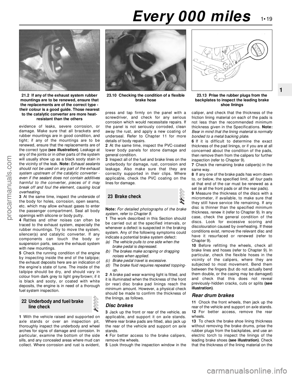
evidence of leaks, severe corrosion, or
damage. Make sure that all brackets and
rubber mountings are in good condition, and
tight; if any of the mountings are to be
renewed, ensure that the replacements are of
the correct type (see illustration). Leakage at
any of the joints or in other parts of the system
will usually show up as a black sooty stain in
the vicinity of the leak. Note:Exhaust sealants
should not be used on any part of the exhaust
system upstream of the catalytic converter -
even if the sealant does not contain additives
harmful to the converter, pieces of it may
break off and foul the element, causing local
overheating.
3At the same time, inspect the underside of
the body for holes, corrosion, open seams,
etc. which may allow exhaust gases to enter
the passenger compartment. Seal all body
openings with silicone or body putty.
4Rattles and other noises can often be
traced to the exhaust system, especially the
rubber mountings. Try to move the system,
silencer(s) and catalytic converter. If any
components can touch the body or
suspension parts, secure the exhaust system
with new mountings.
5Check the running condition of the engine
by inspecting inside the end of the tailpipe;
the exhaust deposits here are an indication of
the engine’s state of tune. The inside of the
tailpipe should be dry, and should vary in
colour from dark grey to light grey/brown; if it
is black and sooty, or coated with white
deposits, the engine is in need of a thorough
fuel system inspection.
1With the vehicle raised and supported on
axle stands or over an inspection pit,
thoroughly inspect the underbody and wheel
arches for signs of damage and corrosion. In
particular, examine the bottom of the side
sills, and any concealed areas where mud can
collect. Where corrosion and rust is evident,press and tap firmly on the panel with a
screwdriver, and check for any serious
corrosion which would necessitate repairs. If
the panel is not seriously corroded, clean
away the rust, and apply a new coating of
underseal. Refer to Chapter 11 for more
details of body repairs.
2At the same time, inspect the PVC-coated
lower body panels for stone damage and
general condition.
3Inspect all of the fuel and brake lines on the
underbody for damage, rust, corrosion and
leakage. Also make sure that they are
correctly supported in their clips. Where
applicable, check the PVC coating on the
lines for damage.
Note:For detailed photographs of the brake
system, refer to Chapter 9.
1The work described in this Section should
be carried out at the specified intervals, or
whenever a defect is suspected in the braking
system. Any of the following symptoms could
indicate a potential brake system defect:
(a) The vehicle pulls to one side when the
brake pedal is depressed.
(b) The brakes make scraping or dragging
noises when applied.
(c) Brake pedal travel is excessive.
(d) The brake fluid requires repeated topping-
up.
2A brake pad wear warning light is fitted, and
it is illuminated when the thickness of the front
(or rear) disc brake pad linings reach the
minimum amount. However, a physical check
should be made to confirm the thickness of
the linings, as follows.
Disc brakes
3Jack up the front or rear of the vehicle, as
applicable, and support it on axle stands.
Where rear brake pads are fitted, also jack up
the rear of the vehicle and support on axle
stands.
4For better access to the brake calipers,
remove the wheels.
5Look through the inspection window in thecaliper, and check that the thickness of the
friction lining material on each of the pads is
not less than the recommended minimum
thickness given in the Specifications. Note:
Bear in mind that the lining material is normally
bonded to a metal backing plate.
6If it is difficult to determine the exact
thickness of the pad linings, or if you are at all
concerned about the condition of the pads,
then remove them from the calipers for further
inspection (refer to Chapter 9).
7Check the remaining brake caliper(s) in the
same way.
8If any one of the brake pads has worn down
to, or below, the specified limit, all fourpads
at that end of the car must be renewed as a
set (ie all the front pads or all the rear pads).
9Measure the thickness of the discs with a
micrometer, if available, to make sure that
they still have service life remaining. If any
disc is thinner than the specified minimum
thickness, renew it (refer to Chapter 9). In any
case, check the general condition of the
discs. Look for excessive scoring and
discolouration caused by overheating. If these
conditions exist, remove the relevant disc and
have it resurfaced or renewed (refer to
Chapter 9).
10Before refitting the wheels, check all
brake lines and hoses (refer to Chapter 9). In
particular, check the flexible hoses in the
vicinity of the calipers, where they are
subjected to most movement. Bend them
between the fingers (but do not actually bend
them double, or the casing may be damaged)
and check that this does not reveal
previously-hidden cracks, cuts or splits (see
illustration).
Rear drum brakes
11Chock the front wheels, then jack up the
rear of the vehicle and support on axle stands.
12For better access, remove the rear
wheels.
13To check the brake shoe lining thickness
without removing the brake drums, prise the
rubber plugs from the backplates, and use an
electric torch to inspect the linings of the
leading brake shoes (see illustration). Check
that the thickness of the lining material on the
23 Brake check
22 Underbody and fuel/brake
line check
1•19
121.2 If any of the exhaust system rubber
mountings are to be renewed, ensure that
the replacements are of the correct type -
their colour is a good guide. Those nearest
to the catalytic converter are more heat-
resistant than the others23.10 Checking the condition of a flexible
brake hose23.13 Prise the rubber plugs from the
backplates to inspect the leading brake
shoe linings
Every 000 miles
procarmanuals.com
Page 34 of 279
brake shoes is not less than the
recommendation given in the Specifications.
14If it is difficult to determine the exact
thickness of the brake shoe linings, or if you
are at all concerned about the condition of the
shoes, then remove the rear drums for a more
comprehensive inspection (refer to Chapter 9)
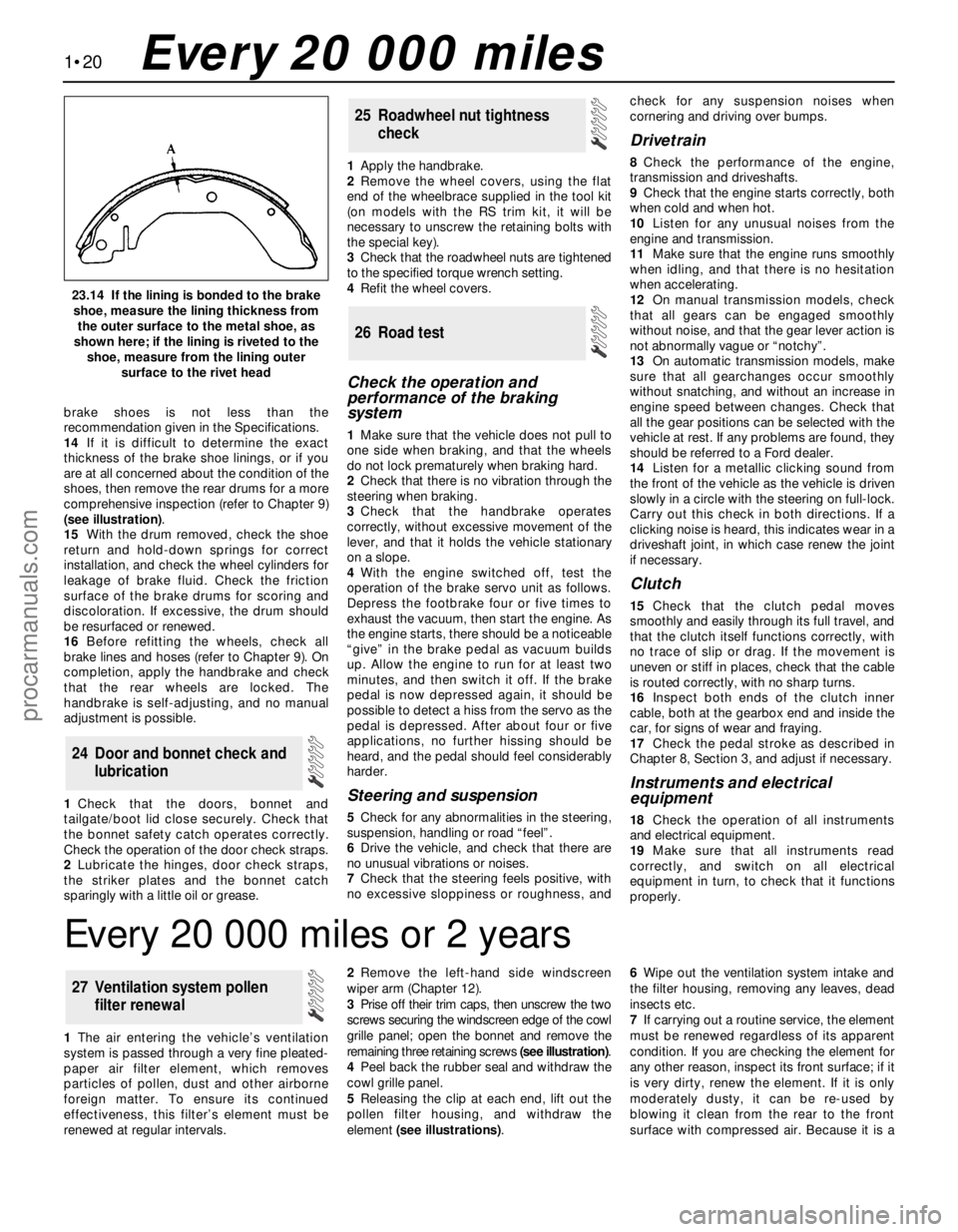
(see illustration).
15With the drum removed, check the shoe
return and hold-down springs for correct
installation, and check the wheel cylinders for
leakage of brake fluid. Check the friction
surface of the brake drums for scoring and
discoloration. If excessive, the drum should
be resurfaced or renewed.
16Before refitting the wheels, check all
brake lines and hoses (refer to Chapter 9). On
completion, apply the handbrake and check
that the rear wheels are locked. The
handbrake is self-adjusting, and no manual
adjustment is possible.
1Check that the doors, bonnet and
tailgate/boot lid close securely. Check that
the bonnet safety catch operates correctly.
Check the operation of the door check straps.
2Lubricate the hinges, door check straps,
the striker plates and the bonnet catch
sparingly with a little oil or grease.1Apply the handbrake.
2Remove the wheel covers, using the flat
end of the wheelbrace supplied in the tool kit
(on models with the RS trim kit, it will be
necessary to unscrew the retaining bolts with
the special key).
3Check that the roadwheel nuts are tightened
to the specified torque wrench setting.
4Refit the wheel covers.
Check the operation and
performance of the braking
system
1Make sure that the vehicle does not pull to
one side when braking, and that the wheels
do not lock prematurely when braking hard.
2Check that there is no vibration through the
steering when braking.
3Check that the handbrake operates
correctly, without excessive movement of the
lever, and that it holds the vehicle stationary
on a slope.
4With the engine switched off, test the
operation of the brake servo unit as follows.
Depress the footbrake four or five times to
exhaust the vacuum, then start the engine. As
the engine starts, there should be a noticeable
“give” in the brake pedal as vacuum builds
up. Allow the engine to run for at least two
minutes, and then switch it off. If the brake
pedal is now depressed again, it should be
possible to detect a hiss from the servo as the
pedal is depressed. After about four or five
applications, no further hissing should be
heard, and the pedal should feel considerably
harder.
Steering and suspension
5Check for any abnormalities in the steering,
suspension, handling or road “feel”.
6Drive the vehicle, and check that there are
no unusual vibrations or noises.
7Check that the steering feels positive, with
no excessive sloppiness or roughness, andcheck for any suspension noises when
cornering and driving over bumps.
Drivetrain
8Check the performance of the engine,
transmission and driveshafts.
9Check that the engine starts correctly, both
when cold and when hot.
10Listen for any unusual noises from the
engine and transmission.
11Make sure that the engine runs smoothly
when idling, and that there is no hesitation
when accelerating.
12On manual transmission models, check
that all gears can be engaged smoothly
without noise, and that the gear lever action is
not abnormally vague or “notchy”.
13On automatic transmission models, make
sure that all gearchanges occur smoothly
without snatching, and without an increase in
engine speed between changes. Check that
all the gear positions can be selected with the
vehicle at rest. If any problems are found, they
should be referred to a Ford dealer.
14Listen for a metallic clicking sound from
the front of the vehicle as the vehicle is driven
slowly in a circle with the steering on full-lock.
Carry out this check in both directions. If a
clicking noise is heard, this indicates wear in a
driveshaft joint, in which case renew the joint
if necessary.
Clutch
15Check that the clutch pedal moves
smoothly and easily through its full travel, and
that the clutch itself functions correctly, with
no trace of slip or drag. If the movement is
uneven or stiff in places, check that the cable
is routed correctly, with no sharp turns.
16Inspect both ends of the clutch inner
cable, both at the gearbox end and inside the
car, for signs of wear and fraying.
17Check the pedal stroke as described in
Chapter 8, Section 3, and adjust if necessary.
Instruments and electrical
equipment
18Check the operation of all instruments
and electrical equipment.
19Make sure that all instruments read
correctly, and switch on all electrical
equipment in turn, to check that it functions
properly.
26 Road test
25 Roadwheel nut tightness
check
24 Door and bonnet check and
lubrication
1•20
23.14 If the lining is bonded to the brake
shoe, measure the lining thickness from
the outer surface to the metal shoe, as
shown here; if the lining is riveted to the
shoe, measure from the lining outer
surface to the rivet head
Every 20 000 miles
Every 20 000 miles or 2 years
1The air entering the vehicle’s ventilation
system is passed through a very fine pleated-
paper air filter element, which removes
particles of pollen, dust and other airborne
foreign matter. To ensure its continued
effectiveness, this filter’s element must be
renewed at regular intervals.2Remove the left-hand side windscreen
wiper arm (Chapter 12).
3Prise off their trim caps, then unscrew the two
screws securing the windscreen edge of the cowl
grille panel; open the bonnet and remove the
remaining three retaining screws (see illustration).
4Peel back the rubber seal and withdraw the
cowl grille panel.
5Releasing the clip at each end, lift out the
pollen filter housing, and withdraw the
element (see illustrations).6Wipe out the ventilation system intake and
the filter housing, removing any leaves, dead
insects etc.
7If carrying out a routine service, the element
must be renewed regardless of its apparent
condition. If you are checking the element for
any other reason, inspect its front surface; if it
is very dirty, renew the element. If it is only
moderately dusty, it can be re-used by
blowing it clean from the rear to the front
surface with compressed air. Because it is a
27 Ventilation system pollen
filter renewal
procarmanuals.com
Page 41 of 279
Chapter 2 Part A:
In-car engine repair procedures
Auxiliary drivebelt check and renewal . . . . . . . . . . . . . See Chapter 1
Camshaft oil seals - renewal . . . . . . . . . . . . . . . . . . . . . . . . . . . . . . . 12
Camshafts and hydraulic tappets - removal, inspection
and refitting . . . . . . . . . . . . . . . . . . . . . . . . . . . . . . . . . . . . . . . . . . 13
Compression test - description and interpretation . . . . . . . . . . . . . . 3
Crankshaft oil seals - renewal . . . . . . . . . . . . . . . . . . . . . . . . . . . . . . 20
Crankshaft pulley - removal and refitting . . . . . . . . . . . . . . . . . . . . . 8
Cylinder head - removal and refitting . . . . . . . . . . . . . . . . . . . . . . . . 14
Cylinder head and valve components - cleaning and
inspection . . . . . . . . . . . . . . . . . . . . . . . . . . . . . . . . . . . See Chapter 2B
Cylinder head cover - removal and refitting . . . . . . . . . . . . . . . . . . . 5
Engine oil and filter change . . . . . . . . . . . . . . . . . . . . . See Chapter 1
Engine oil level check . . . . . . . . . . . . . . . . . . . . . . . . . . See Chapter 1
Engine overhaul - general information . . . . . . . . . . . . . See Chapter 2B
Engine/transmission - removal and refitting . . . . . . . . See Chapter 2B
Engine/transmission mountings - inspection and renewal . . . . . . . . 22
Exhaust manifold - removal, inspection and refitting . . . . . . . . . . . . 7Flywheel/driveplate - removal, inspection and refitting . . . . . . . . . . 21
General information . . . . . . . . . . . . . . . . . . . . . . . . . . . . . . . . . . . . . . 1
Inlet manifold - removal and refitting . . . . . . . . . . . . . . . . . . . . . . . . 6
Oil cooler - removal and refitting . . . . . . . . . . . . . . . . . . . . . . . . . . . . 17
Oil level sensor - removal and refitting . . . . . . . . . . . . . . . . . . . . . . . 18
Oil pressure warning light switch - removal and refitting . . . . . . . . . 19
Oil pump - removal, inspection and refitting . . . . . . . . . . . . . . . . . . . 16
Repair operations possible with the engine in the vehicle . . . . . . . . 2
Spark plug renewal . . . . . . . . . . . . . . . . . . . . . . . . . . . See Chapter 1
Sump - removal and refitting . . . . . . . . . . . . . . . . . . . . . . . . . . . . . . . 15
Timing belt - removal, refitting and adjustment . . . . . . . . . . . . . . . . 10
Timing belt covers - removal and refitting . . . . . . . . . . . . . . . . . . . . . 9
Timing belt tensioner and toothed pulleys - removal,
inspection and refitting . . . . . . . . . . . . . . . . . . . . . . . . . . . . . . . . . 11
Top Dead Centre (TDC) for No 1 piston - locating . . . . . . . . . . . . . . 4
Water pump - removal and refitting . . . . . . . . . . . . . . . See Chapter 3
General
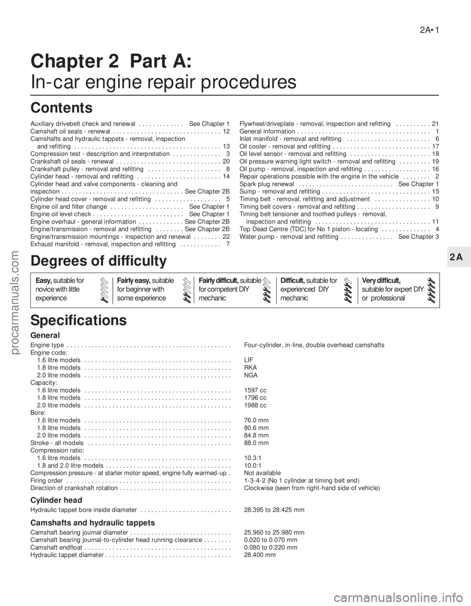
Engine type . . . . . . . . . . . . . . . . . . . . . . . . . . . . . . . . . . . . . . . . . . . . . . . Four-cylinder, in-line, double overhead camshafts
Engine code:
1.6 litre models . . . . . . . . . . . . . . . . . . . . . . . . . . . . . . . . . . . . . . . . . . LIF
1.8 litre models . . . . . . . . . . . . . . . . . . . . . . . . . . . . . . . . . . . . . . . . . . RKA
2.0 litre models . . . . . . . . . . . . . . . . . . . . . . . . . . . . . . . . . . . . . . . . . . NGA
Capacity:
1.6 litre models . . . . . . . . . . . . . . . . . . . . . . . . . . . . . . . . . . . . . . . . . . 1597 cc
1.8 litre models . . . . . . . . . . . . . . . . . . . . . . . . . . . . . . . . . . . . . . . . . . 1796 cc
2.0 litre models . . . . . . . . . . . . . . . . . . . . . . . . . . . . . . . . . . . . . . . . . . 1988 cc
Bore:
1.6 litre models . . . . . . . . . . . . . . . . . . . . . . . . . . . . . . . . . . . . . . . . . . 76.0 mm
1.8 litre models . . . . . . . . . . . . . . . . . . . . . . . . . . . . . . . . . . . . . . . . . . 80.6 mm
2.0 litre models . . . . . . . . . . . . . . . . . . . . . . . . . . . . . . . . . . . . . . . . . . 84.8 mm
Stroke - all models . . . . . . . . . . . . . . . . . . . . . . . . . . . . . . . . . . . . . . . . . 88.0 mm
Compression ratio:
1.6 litre models . . . . . . . . . . . . . . . . . . . . . . . . . . . . . . . . . . . . . . . . . . 10.3:1
1.8 and 2.0 litre models . . . . . . . . . . . . . . . . . . . . . . . . . . . . . . . . . . . . 10.0:1
Compression pressure - at starter motor speed, engine fully warmed-up .Not available
Firing order . . . . . . . . . . . . . . . . . . . . . . . . . . . . . . . . . . . . . . . . . . . . . . . 1-3-4-2 (No 1 cylinder at timing belt end)
Direction of crankshaft rotation . . . . . . . . . . . . . . . . . . . . . . . . . . . . . . . . Clockwise (seen from right-hand side of vehicle)
Cylinder head
Hydraulic tappet bore inside diameter . . . . . . . . . . . . . . . . . . . . . . . . . . 28.395 to 28.425 mm
Camshafts and hydraulic tappets
Camshaft bearing journal diameter . . . . . . . . . . . . . . . . . . . . . . . . . . . . . 25.960 to 25.980 mm
Camshaft bearing journal-to-cylinder head running clearance . . . . . . . . 0.020 to 0.070 mm
Camshaft endfloat . . . . . . . . . . . . . . . . . . . . . . . . . . . . . . . . . . . . . . . . . . 0.080 to 0.220 mm
Hydraulic tappet diameter . . . . . . . . . . . . . . . . . . . . . . . . . . . . . . . . . . . . 28.400 mm
2A•1
Easy,suitable for
novice with little
experienceFairly easy,suitable
for beginner with
some experienceFairly difficult,suitable
for competent DIY
mechanicDifficult,suitable for
experienced DIY
mechanicVery difficult,
suitable for expert DIY
or professional
Degrees of difficulty
Specifications Contents2A
procarmanuals.com
Page 49 of 279
9Remove the nuts and detach the manifold
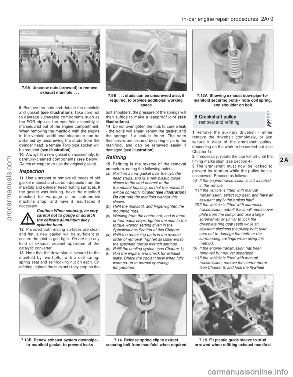
and gasket (see illustration). Take care not
to damage vulnerable components such as
the EGR pipe as the manifold assembly is
manoeuvred out of the engine compartment.
When removing the manifold with the engine
in the vehicle, additional clearance can be
obtained by unscrewing the studs from the
cylinder head; a female Torx-type socket will
be required (see illustration).
10Always fit a new gasket on reassembly, to
carefully-cleaned components (see below).
Do notattempt to re-use the original gasket.
Inspection
11Use a scraper to remove all traces of old
gasket material and carbon deposits from the
manifold and cylinder head mating surfaces. If
the gasket was leaking, have the manifold
checked for warpage at an automotive
machine shop, and have it resurfaced if
necessary.
Caution: When scraping, be very
careful not to gouge or scratch
the delicate aluminium alloy
cylinder head.
12Provided both mating surfaces are clean
and flat, a new gasket will be sufficient to
ensure the joint is gas-tight. Do notuse any
kind of exhaust sealant upstream of the
catalytic converter.
13Note that the downpipe is secured to the
manifold by two bolts, with a coil spring,
spring seat and self-locking nut on each. On
refitting, tighten the nuts until they stop on thebolt shoulders; the pressure of the springs will
then suffice to make a leakproof joint (see
illustrations).
14Do not overtighten the nuts to cure a leak
- the bolts will shear; renew the gasket and
the springs if a leak is found. The bolts
themselves are secured by spring clips to the
manifold, and can be renewed easily if
damaged (see illustration).
Refitting
15Refitting is the reverse of the removal
procedure, noting the following points:
(a) Position a new gasket over the cylinder
head studs, and fit a new plastic guide
sleeve to the stud nearest to the
thermostat housing, so that the manifold
will be correctly located (see illustration).
Do notrefit the manifold without this
sleeve.
(b) Refit the manifold, and finger-tighten the
mounting nuts.
(c) Working from the centre out, and in three
or four equal steps, tighten the nuts to the
torque wrench setting given in the
Specifications Section of this Chapter.
(d) Refit the remaining parts in the reverse
order of removal. Tighten all fasteners to
the specified torque wrench settings.
(e) Refill the cooling system (see Chapter 1).
(f) Run the engine, and check for exhaust
leaks. Check the coolant level when fully
warmed-up to normal operating
temperature.1Remove the auxiliary drivebelt - either
remove the drivebelt completely, or just
secure it clear of the crankshaft pulley,
depending on the work to be carried out (see
Chapter 1).
2If necessary, rotate the crankshaft until the
timing marks align (see Section 4).
3The crankshaft must now be locked to
prevent its rotation while the pulley bolt is
unscrewed. Proceed as follows:
(a) If the engine/transmission is still installed
in the vehicle:
(1) If the vehicle is fitted with manual
transmission, select top gear, and have an
assistant apply the brakes hard.
(2) If the vehicle is fitted with automatic
transmission, unbolt the small metal cover
plate from the sump, and use a large
screwdriver or similar to lock the
driveplate ring gear teeth while an
assistant slackens the pulley bolt; take
care not to damage the teeth or the
surrounding castings when using this
method.
(b) If the engine/transmission has been
removed but not yet separated:
(1) If the vehicle is fitted with manual
transmission, remove the starter motor
(see Chapter 5) and lock the flywheel
8 Crankshaft pulley -
removal and refitting
In-car engine repair procedures 2A•9
2A
7.13B Renew exhaust system downpipe-
to-manifold gasket to prevent leaks7.14 Release spring clip to extract
securing bolt from manifold, when required7.15 Fit plastic guide sleeve to stud
arrowed when refitting exhaust manifold
7.9A Unscrew nuts (arrowed) to remove
exhaust manifold . . .
7.9B . . . studs can be unscrewed also, if
required, to provide additional working
space7.13A Showing exhaust downpipe-to-
manifold securing bolts - note coil spring,
and shoulder on bolt
procarmanuals.com