1993 FORD MONDEO tow bar
[x] Cancel search: tow barPage 40 of 279
1•26Every 60 000 miles
Every 60 000 miles
Refer to Chapter 2, Part A.
Warning: Petrol is extremely
flammable, so extra precautions
must be taken when working on
any part of the fuel system. Do not smoke,
or allow open flames or bare light bulbs,
near the work area. Also, do not work in a
garage if a gas appliance with a pilot light is
present. While performing any work on the
fuel system, wear safety glasses, and have
a suitable (Class B) fire extinguisher on
hand. If you spill any fuel on your skin, rinse
it off immediately with soap and water.
1The fuel filter is located at the front right-
hand corner of the fuel tank, just forward of
the vehicle’s right-hand rear jacking point. The
filter performs a vital role in keeping dirt and
other foreign matter out of the fuel system,
and so must be renewed at regular intervals,or whenever you have reason to suspect that
it may be clogged. It is always unpleasant
working under a vehicle - pressure-washing or
hosing clean the underbody in the filter’s
vicinity will make working conditions more
tolerable, and will reduce the risk of getting
dirt into the fuel system.
2Relieve any residual pressure in the system
by removing the fuel pump fuse (No 14) and
starting the engine; allow the engine to idle until
it dies. Turn the engine over once or twice on
the starter, to ensure that all pressure is
released, then switch off the ignition.
Warning: This procedure will
merely relieve the pressure
necessary for the engine to run -
remember that fuel will still be present in
the system components, and take
precautions before disconnecting them.
3Noting the comments made in Section 1 of
Chapter 5, disconnect the battery earth terminal.
4Jack up the rear right-hand side of the
vehicle, and support it securely on an axle stand.
5Using rag to soak up any spilt fuel, release
the fuel feed and outlet pipe unions from the
filter, by squeezing together the protruding
locking lugs on each union, and carefully
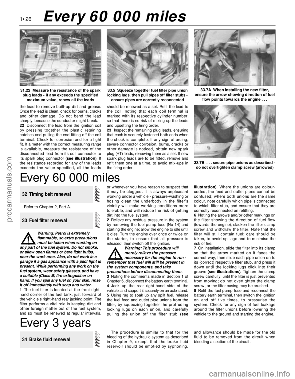
pulling the union off the filter stub (seeillustration). Where the unions are colour-
coded, the feed and outlet pipes cannot be
confused; where both unions are the same
colour, note carefully which pipe is connected
to which filter stub, and ensure that they are
correctly reconnected on refitting.
6Noting the arrows and/or other markings on
the filter showing the direction of fuel flow
(towards the engine), slacken the filter clamp
screw and withdraw the filter. Note that the
filter will still contain fuel; care should be
taken, to avoid spillage and to minimise the
risk of fire.
7On installation, slide the filter into its clamp
so that the arrow marked on it faces the
correct way, then slide each pipe union on to
its (correct) respective filter stub, and press it
down until the locking lugs click into their
groove (see illustrations). Tighten the clamp
screw carefully, until the filter is just prevented
from moving; do not overtighten the clamp
screw, or the filter casing may be crushed.
8Refit the fuel pump fuse and reconnect the
battery earth terminal, then switch the ignition
on and off five times, to pressurise the
system. Check for any sign of fuel leakage
around the filter unions before lowering the
vehicle to the ground and starting the engine.
33 Fuel filter renewal
32 Timing belt renewal
33.5 Squeeze together fuel filter pipe union
locking lugs, then pull pipes off filter stubs -
ensure pipes are correctly reconnected33.7A When installing the new filter,
ensure the arrow showing direction of fuel
flow points towards the engine . . .
Every 3 years
The procedure is similar to that for the
bleeding of the hydraulic system as described
in Chapter 9, except that the brake fluid
reservoir should be emptied by syphoning,and allowance should be made for the old
fluid to be removed from the circuit when
bleeding a section of the circuit.
34 Brake fluid renewal
31.22 Measure the resistance of the spark
plug leads - if any exceeds the specified
maximum value, renew all the leads
the lead to remove built-up dirt and grease.
Once the lead is clean, check for burns, cracks
and other damage. Do not bend the lead
sharply, because the conductor might break.
22Disconnect the lead from the ignition coil
by pressing together the plastic retaining
catches and pulling the end fitting off the coil
terminal. Check for corrosion and for a tight
fit. If a meter with the correct measuring range
is available, measure the resistance of the
disconnected lead from its coil connector to
its spark plug connector (see illustration). If
the resistance recorded for any of the leads
exceeds the value specified, all the leadsshould be renewed as a set. Refit the lead to
the coil, noting that each coil terminal is
marked with its respective cylinder number,
so that there is no risk of mixing up the leads
and upsetting the firing order.
23Inspect the remaining plug leads, ensuring
that each is securely fastened both ends when
the check is complete. If any sign of arcing,
severe connector corrosion, burns, cracks or
other damage is noticed, obtain new spark
plug (HT) leads, renewing them as a set. If new
spark plug leads are to be fitted, remove and
refit them one at a time, to avoid mix-ups in
the firing order.
33.7B . . . secure pipe unions as described -
do not overtighten clamp screw (arrowed)
procarmanuals.com
Page 78 of 279
grinding or head resurfacing. Use
compressed air, if available, to blow out all the
oil holes and passages.
2Beginning at one end of the head, lubricate
and install the first valve. Apply molybdenum
disulphide-based grease or clean engine oil to
the valve stem, and refit the valve. Where the
original valves are being re-used, ensure that
each is refitted in its original guide. If new
valves are being fitted, insert them into the
locations to which they have been ground.
3Fit the plastic protector supplied with new
valve spring lower seat/stem oil seals to the
end of the valve stem, then put the new seal
squarely on top of the guide, and leave it
there; the action of refitting the valve spring
presses the lower seat/stem oil seal into place
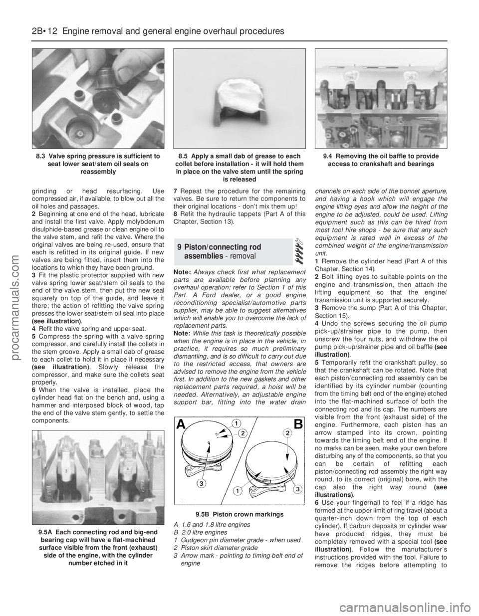
(see illustration).
4Refit the valve spring and upper seat.
5Compress the spring with a valve spring
compressor, and carefully install the collets in
the stem groove. Apply a small dab of grease
to each collet to hold it in place if necessary
(see illustration). Slowly release the
compressor, and make sure the collets seat
properly.
6When the valve is installed, place the
cylinder head flat on the bench and, using a
hammer and interposed block of wood, tap
the end of the valve stem gently, to settle the
components.7Repeat the procedure for the remaining
valves. Be sure to return the components to
their original locations - don’t mix them up!
8Refit the hydraulic tappets (Part A of this
Chapter, Section 13).
Note:Always check first what replacement
parts are available before planning any
overhaul operation; refer to Section 1 of this
Part. A Ford dealer, or a good engine
reconditioning specialist/automotive parts
supplier, may be able to suggest alternatives
which will enable you to overcome the lack of
replacement parts.
Note:While this task is theoretically possible
when the engine is in place in the vehicle, in
practice, it requires so much preliminary
dismantling, and is so difficult to carry out due
to the restricted access, that owners are
advised to remove the engine from the vehicle
first. In addition to the new gaskets and other
replacement parts required, a hoist will be
needed. Alternatively, an adjustable engine
support bar, fitting into the water drainchannels on each side of the bonnet aperture,
and having a hook which will engage the
engine lifting eyes and allow the height of the
engine to be adjusted, could be used. Lifting
equipment such as this can be hired from
most tool hire shops - be sure that any such
equipment is rated well in excess of the
combined weight of the engine/transmission
unit.
1Remove the cylinder head (Part A of this
Chapter, Section 14).
2Bolt lifting eyes to suitable points on the
engine and transmission, then attach the
lifting equipment so that the engine/
transmission unit is supported securely.
3Remove the sump (Part A of this Chapter,
Section 15).
4Undo the screws securing the oil pump
pick-up/strainer pipe to the pump, then
unscrew the four nuts, and withdraw the oil
pump pick-up/strainer pipe and oil baffle (see
illustration).
5Temporarily refit the crankshaft pulley, so
that the crankshaft can be rotated. Note that
each piston/connecting rod assembly can be
identified by its cylinder number (counting
from the timing belt end of the engine) etched
into the flat-machined surface of both the
connecting rod and its cap. The numbers are
visible from the front (exhaust side) of the
engine. Furthermore, each piston has an
arrow stamped into its crown, pointing
towards the timing belt end of the engine. If
no marks can be seen, make your own before
disturbing any of the components, so that you
can be certain of refitting each
piston/connecting rod assembly the right way
round, to its correct (original) bore, with the
cap also the right way round (see
illustrations).
6Use your fingernail to feel if a ridge has
formed at the upper limit of ring travel (about a
quarter-inch down from the top of each
cylinder). If carbon deposits or cylinder wear
have produced ridges, they must be
completely removed with a special tool (see
illustration). Follow the manufacturer’s
instructions provided with the tool. Failure to
remove the ridges before attempting to
9 Piston/connecting rod
assemblies- removal
2B•12 Engine removal and general engine overhaul procedures
8.3 Valve spring pressure is sufficient to
seat lower seat/stem oil seals on
reassembly8.5 Apply a small dab of grease to each
collet before installation - it will hold them
in place on the valve stem until the spring
is released9.4 Removing the oil baffle to provide
access to crankshaft and bearings
9.5A Each connecting rod and big-end
bearing cap will have a flat-machined
surface visible from the front (exhaust)
side of the engine, with the cylinder
number etched in it
9.5B Piston crown markings
A 1.6 and 1.8 litre engines
B 2.0 litre engines
1 Gudgeon pin diameter grade - when used
2 Piston skirt diameter grade
3 Arrow mark - pointing to timing belt end of
engine
procarmanuals.com
Page 166 of 279
Refitting
15Locate the strut assembly (together with
the coil spring compressor tool) under the
wheel arch, and locate the bracket on the
bump stop on the rear suspension
crossmember. Insert the two bolts securing
the upper mounting to the underbody tower,
and tighten them to the specified torque.
16Carefully release the coil spring
compressor tool, making sure that the spring
locates correctly in the upper and lower seats,
and that the strut bracket locates on the
crossmember bump stop. The bump stop is
tapered inwards, and the strut bracket should
be fully engaged with it before releasing the
coil spring.
17Raise the knuckle and engage it with the
strut, then insert the clamp bolt and tighten to
the specified torque.
18Reconnect the front and rear lower armsto the knuckle, and finger-tighten the bolts at
this stage.
19Reconnect the tie-bar to the bottom of the
knuckle, and finger-tighten the bolt at this
stage.
20Refit the anti-roll bar link to the lower arm,
and tighten the nut to the specified torque.
21On disc brake models, refit the caliper
bracket to the knuckle, and tighten the
mounting bolts to the specified torque (see
Chapter 9). Make sure that the flexible brake
hose is not twisted.
22On drum brake models, connect the
flexible hose to the strut, insert the clip, then
insert the rigid brake line and tighten the union
nut. Remove the brake hose clamp, then
bleed the hydraulic brake circuit as described
in Chapter 9.
23Where applicable, reconnect the wiring
multi-plug for the adaptive damping, and clip
the wiring to the strut.24Where applicable, refit the ABS sensor as
described in Chapter 9, and clip the wiring to
the strut.
25Refit the wheel, and lower the vehicle to
the ground.
26With the weight of the vehicle on the rear
suspension, fully tighten the lower arm and
tie-bar mounting bolts.
1The procedure is similar to that for the front
suspension strut, and reference should be made
to Section 5. Note that the spring compressor
tools will already be in position on the coil spring
following the removal operation. Refer also to
the accompanying illustrations for details of the
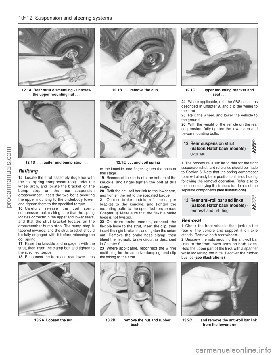
separate components (see illustrations).
Removal
1Chock the front wheels, then jack up the
rear of the vehicle and support it on axle
stands. Remove both rear wheels.
2Unscrew the nuts securing the anti-roll bar
links to the front lower arms on both sides.
Hold the upper part of the links with a spanner
while loosening the nuts. Recover the rubber
bushes (see illustrations).
13 Rear anti-roll bar and links
(Saloon/Hatchback models) -
removal and refitting
12 Rear suspension strut
(Saloon/Hatchback models)-
overhaul
10•12 Suspension and steering systems
12.1A Rear strut dismantling - unscrew
the upper mounting nut . . .12.1B . . . remove the cup . . .12.1C . . . upper mounting bracket and
seat . . .
13.2A Loosen the nut . . .13.2B . . . remove the nut and rubber
bush . . .
12.1D . . . gaiter and bump stop . . .12.1E . . . and coil spring
13.2C . . . and remove the anti-roll bar link
from the lower arm
procarmanuals.com
Page 194 of 279
14Release the door-ajar sensor from the clip
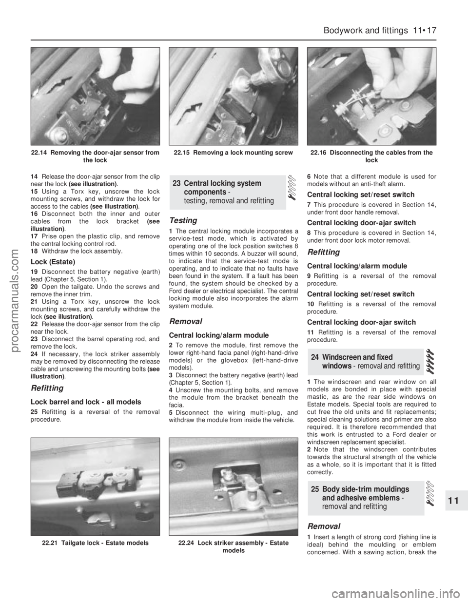
near the lock (see illustration).
15Using a Torx key, unscrew the lock
mounting screws, and withdraw the lock for
access to the cables (see illustration).
16Disconnect both the inner and outer
cables from the lock bracket (see
illustration).
17Prise open the plastic clip, and remove
the central locking control rod.
18Withdraw the lock assembly.
Lock (Estate)
19Disconnect the battery negative (earth)
lead (Chapter 5, Section 1).
20Open the tailgate. Undo the screws and
remove the inner trim.
21Using a Torx key, unscrew the lock
mounting screws, and carefully withdraw the
lock (see illustration).
22Release the door-ajar sensor from the clip
near the lock.
23Disconnect the barrel operating rod, and
remove the lock.
24If necessary, the lock striker assembly
may be removed by disconnecting the release
cable and unscrewing the mounting bolts (see
illustration).
Refitting
Lock barrel and lock - all models
25Refitting is a reversal of the removal
procedure.
Testing
1The central locking module incorporates a
service-test mode, which is activated by
operating one of the lock position switches 8
times within 10 seconds. A buzzer will sound,
to indicate that the service-test mode is
operating, and to indicate that no faults have
been found in the system. If a fault has been
found, the system should be checked by a
Ford dealer or electrical specialist. The central
locking module also incorporates the alarm
system module.
Removal
Central locking/alarm module
2To remove the module, first remove the
lower right-hand facia panel (right-hand-drive
models) or the glovebox (left-hand-drive
models).
3Disconnect the battery negative (earth) lead
(Chapter 5, Section 1).
4Unscrew the mounting bolts, and remove
the module from the bracket beneath the
facia.
5Disconnect the wiring multi-plug, and
withdraw the module from inside the vehicle.6Note that a different module is used for
models without an anti-theft alarm.
Central locking set/reset switch
7This procedure is covered in Section 14,
under front door handle removal.
Central locking door-ajar switch
8This procedure is covered in Section 14,
under front door lock motor removal.
Refitting
Central locking/alarm module
9Refitting is a reversal of the removal
procedure.
Central locking set/reset switch
10Refitting is a reversal of the removal
procedure.
Central locking door-ajar switch
11Refitting is a reversal of the removal
procedure.
1The windscreen and rear window on all
models are bonded in place with special
mastic, as are the rear side windows on
Estate models. Special tools are required to
cut free the old units and fit replacements;
special cleaning solutions and primer are also
required. It is therefore recommended that
this work is entrusted to a Ford dealer or
windscreen replacement specialist.
2Note that the windscreen contributes
towards the structural strength of the vehicle
as a whole, so it is important that it is fitted
correctly.
Removal
1Insert a length of strong cord (fishing line is
ideal) behind the moulding or emblem
concerned. With a sawing action, break the
25 Body side-trim mouldings
and adhesive emblems -
removal and refitting
24 Windscreen and fixed
windows - removal and refitting
23 Central locking system
components-
testing, removal and refitting
Bodywork and fittings 11•17
11
22.21 Tailgate lock - Estate models22.24 Lock striker assembly - Estate
models
22.14 Removing the door-ajar sensor from
the lock22.15 Removing a lock mounting screw22.16 Disconnecting the cables from the
lock
procarmanuals.com
Page 199 of 279
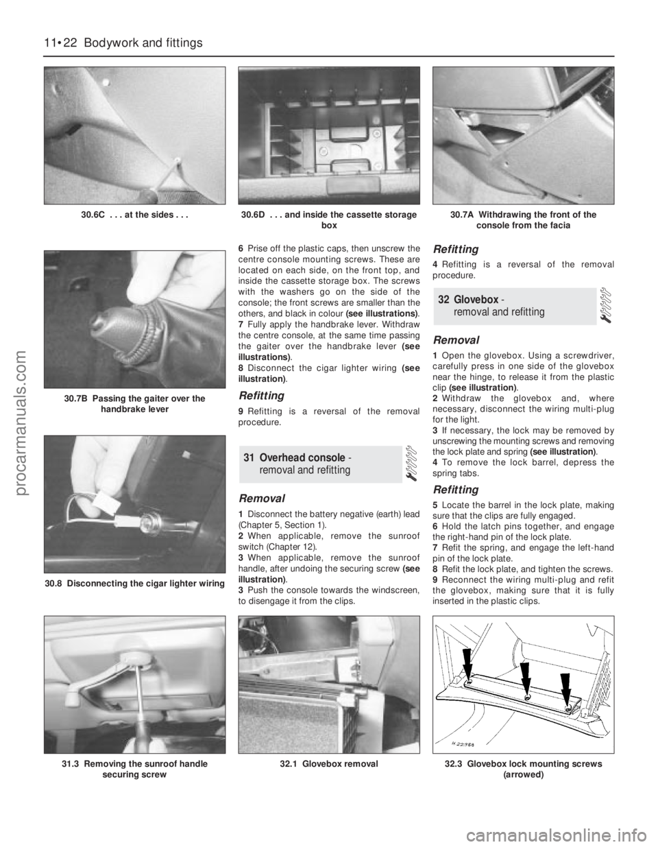
6Prise off the plastic caps, then unscrew the
centre console mounting screws. These are
located on each side, on the front top, and
inside the cassette storage box. The screws
with the washers go on the side of the
console; the front screws are smaller than the
others, and black in colour (see illustrations).
7Fully apply the handbrake lever. Withdraw
the centre console, at the same time passing
the gaiter over the handbrake lever (see
illustrations).
8Disconnect the cigar lighter wiring (see
illustration).
Refitting
9Refitting is a reversal of the removal
procedure.
Removal
1Disconnect the battery negative (earth) lead
(Chapter 5, Section 1).
2When applicable, remove the sunroof
switch (Chapter 12).
3When applicable, remove the sunroof
handle, after undoing the securing screw (see
illustration).
3Push the console towards the windscreen,
to disengage it from the clips.
Refitting
4Refitting is a reversal of the removal
procedure.
Removal
1Open the glovebox. Using a screwdriver,
carefully press in one side of the glovebox
near the hinge, to release it from the plastic
clip (see illustration).
2Withdraw the glovebox and, where
necessary, disconnect the wiring multi-plug
for the light.
3If necessary, the lock may be removed by
unscrewing the mounting screws and removing
the lock plate and spring (see illustration).
4To remove the lock barrel, depress the
spring tabs.
Refitting
5Locate the barrel in the lock plate, making
sure that the clips are fully engaged.
6Hold the latch pins together, and engage
the right-hand pin of the lock plate.
7Refit the spring, and engage the left-hand
pin of the lock plate.
8Refit the lock plate, and tighten the screws.
9Reconnect the wiring multi-plug and refit
the glovebox, making sure that it is fully
inserted in the plastic clips.
32 Glovebox -
removal and refitting
31 Overhead console -
removal and refitting
11•22 Bodywork and fittings
30.6C . . . at the sides . . .30.6D . . . and inside the cassette storage
box30.7A Withdrawing the front of the
console from the facia
31.3 Removing the sunroof handle
securing screw32.1 Glovebox removal
30.8 Disconnecting the cigar lighter wiring
30.7B Passing the gaiter over the
handbrake lever
32.3 Glovebox lock mounting screws
(arrowed)
procarmanuals.com
Page 278 of 279
REF•19Index
Oil pressure warning light switch - 2A•22
Oil pump - 2A•21
Oil seals - 2A•13, 2A•22, 7A•2, 7B•3, REF•4
Oil separator - 6•19
Open-circuit - 12•4
Overcooling - REF•8
Overhead console - 11•22
Overheating - REF•8
Oxygen sensor - 6•11, 6•12, 6•13
P
Pads - 9•3, 9•8
Pedals - 1•17, 4•5, 8•3, 9•10, 9•11
Piston rings - 2B•19
Pistons - 2B•12, 2B•17, 2B•21, 2B•22
Pitching and/or rolling around corners -
REF•11
Plastic components - 11•4
Plenum chamber - 4•3
Poisonous or irritant substances - 0•5
Pollen filter - 1•20, 3•8
Position sensor - 5•4, 6•10, 6•11, 6•12
Positive Crankcase Ventilation (PCV)
system - 1•23, 6•18, 6•19
Power steering - 1•8, 1•10, 6•11, 6•12,
6•13, 10•20, 10•21, 10•22
Power steering fluid - 1•2
Pressure-control relief valve - 9•13
Pressure-cycling and pressure-regulating
switches - 3•10
Project vehicles - 0•4
Pulse-air - 6•17, 6•18
Purge solenoid valve - 6•14
R
Radiator - 3•4, 3•5
Radiator grille - 11•5
Radio - 12•21, 12•22
Radio aerial - 12•22
Reading light - 12•11
Rear light cluster - 12•9, 12•13
Rear window - 12•8, 12•21
Relays - 12•5
Repair procedures - REF•4
Resonator (engine compartment) - 4•3
Respraying - 11•3
Reversing light switch - 7A•3
Road test - 1•20
Roadwheels - 1•17, 1•18, 1•20
Roll-over valves - 4•8
Routine maintenance and servicing- 1•1et
seq
Rubber gaiters- 1•18, 8•7, 8•9, 10•21
Rust holes in bodywork - 11•3
S
Safety first! - 0•5
Scalding - 0•5
Scratches in bodywork - 11•3
Screw threads and fastenings - REF•4
Seat belts - 0•8, 1•13, 11•19, 11•20Seats - 0•8, 11•18, 12•8
Selector assembly - 7B•2
Selector cable - 7B•2
Selector lever position sensor - 7B•2
Selector panel illumination - 12•11
Service indicator - 12•17, 12•18
Servo unit - 9•12, 9•13
Shock absorbers - 0•8, 0•9, 10•14
Shoes - 9•6
Short-circuit - 12•4
Sidelight - 12•9
Solenoid renewal - 5•8
Spare parts - REF•5
Spark plugs - 1•23
Speakers - 12•22
Speed control - 12•20
Speed sensor - 6•11, 6•12, 6•13
Speedometer - 7A•2, 7A•3, 7B•2, 7B•3,
12•15
Springs - 0•9
Starter motor - 5•7
Starter motor fault - REF•7
Starting system - 5•6
Steering - 0•7, 0•8, 0•9, 1•17, 1•20
Steering angles - 10•22
Steering column - 10•18, 10•20
Steering fault - REF•11
Steering knuckle - 10•5
Steering wheel - 10•17
Stop-light switch - 9•15
Striker - 11•13
Struts - 10•6, 10•7, 10•10, 10•12
Sump - 2A•19
Sun visor - 11•20
Sunroof - 11•18, 12•7
Suspension and steering systems- 0•8,
0•9, 1•17, 1•18, 1•20, 10•1et seq
Suspension and steering systems fault
finding - REF•11
Switches - 2A•22, 3•4, 3•5, 3•10, 4•8-
6•11, 6•12, 6•13, 7A•3, 9•15, 11•17,
12•6, 12•7, 12•8, 12•11, 12•18, 12•20
T
Tailgate - 1•8, 1•10, 11•15, 11•16, 12•17,
12•20, REF•12
Tappets - 2A•14
TCS inhibitor switch - 9•15
TCS throttle actuator - 9•15
Temperature gauge fault - REF•12
Thermostat - 3•3, 3•4
Throttle actuator - 9•15
Throttle housing - 4•9
Throttle potentiometer - 6•11, 6•13
Tie-bar - 10•13, 10•16
Timer module - 12•5
Timing - 5•4, 6•10
Timing belt - 1•26, 2A•10, 2A•13
Tools - REF•1, REF•3, REF•4
Top Dead Centre (TDC) for No 1 piston -
2A•6
Towing - 0•11
Track rod end - 10•22Traction Control System - 9•15, 12•7
Transmission- 1•11, 1•17, 2A•24, 2B•3,
2B•4, 7A•1 et seq, 7B•1 et seq, 12•11
Trim mouldings - 11•17
Trim panels - 11•6, 11•20
Trip computer - 12•17
Tyre wear - REF•11
Tyres - 0•10, 1•8
U
Underbody check - 1•19
Upper suspension arm - 10•16
V
Vacuum hoses - 1•15
Vacuum servo unit - 9•12, 9•13
Valve clearances - 2A•5
Valves - 2B•10, 2B•11
Vehicle identification - 0•8, REF•5
Vehicle pulls to one side - REF•10, REF•11
Vehicle speed sensor - 6•11, 6•12, 6•13
Ventilation system - 1•20, 3•7
Voltage regulator - 5•6
W
Warning lights - 12•11
Warning system - 12•17
Washer jets fault - REF•12
Washer nozzle - 12•21
Washer pump fault - REF•12
Washer reservoir and pump - 12•20
Washer system - 1•8, 1•10, 12•18, 12•20
Water pump - 3•6
Weights - 0•6
Wheel alignment - 10•22
Wheel arch liner - 11•24
Wheel bearings - 0•9
Wheel changing - 0•11
Wheel cylinders - 9•8
Wheel sensors - 9•14
Wheel wobble - REF•11
Wheels - 0•10, 1•17, 1•18, 1•20
Wheels locking - REF•11
Window glass - 11•8
Window regulator - 11•9
Windows - 11•17, 12•7, 12•8, 12•21,
REF•12
Windscreen - 0•7, 1•8, 1•10, 11•17, 12•6,
12•8, 12•16, 12•20, 12•21, REF•12
Wiper arms - 12•16
Wiper blade - 1•10
Wiper blade fault - REF•12
Wiper motor - 12•16, 12•17
Wipers - 12•6
Wiper fault - REF•12
Wiring - 1•15
Wiring diagrams- 12•23et seq
Working facilities - REF•3
procarmanuals.com