1993 FORD MONDEO spare wheel
[x] Cancel search: spare wheelPage 11 of 279
0•11Roadside Repairs
To change a wheel, remove the spare
wheel and jack, apply the handbrake, and
chock the wheel diagonally opposite the
one to be changed. On manual transmission
models, select first or reverse gear; on
automatic transmission models, place the
selector lever in “P”. Make sure that the
vehicle is located on firm level ground. Use
the flat end of the wheelbrace carefully to
remove the trim covering the wheel nuts,
then slightly loosen the wheel nuts with the
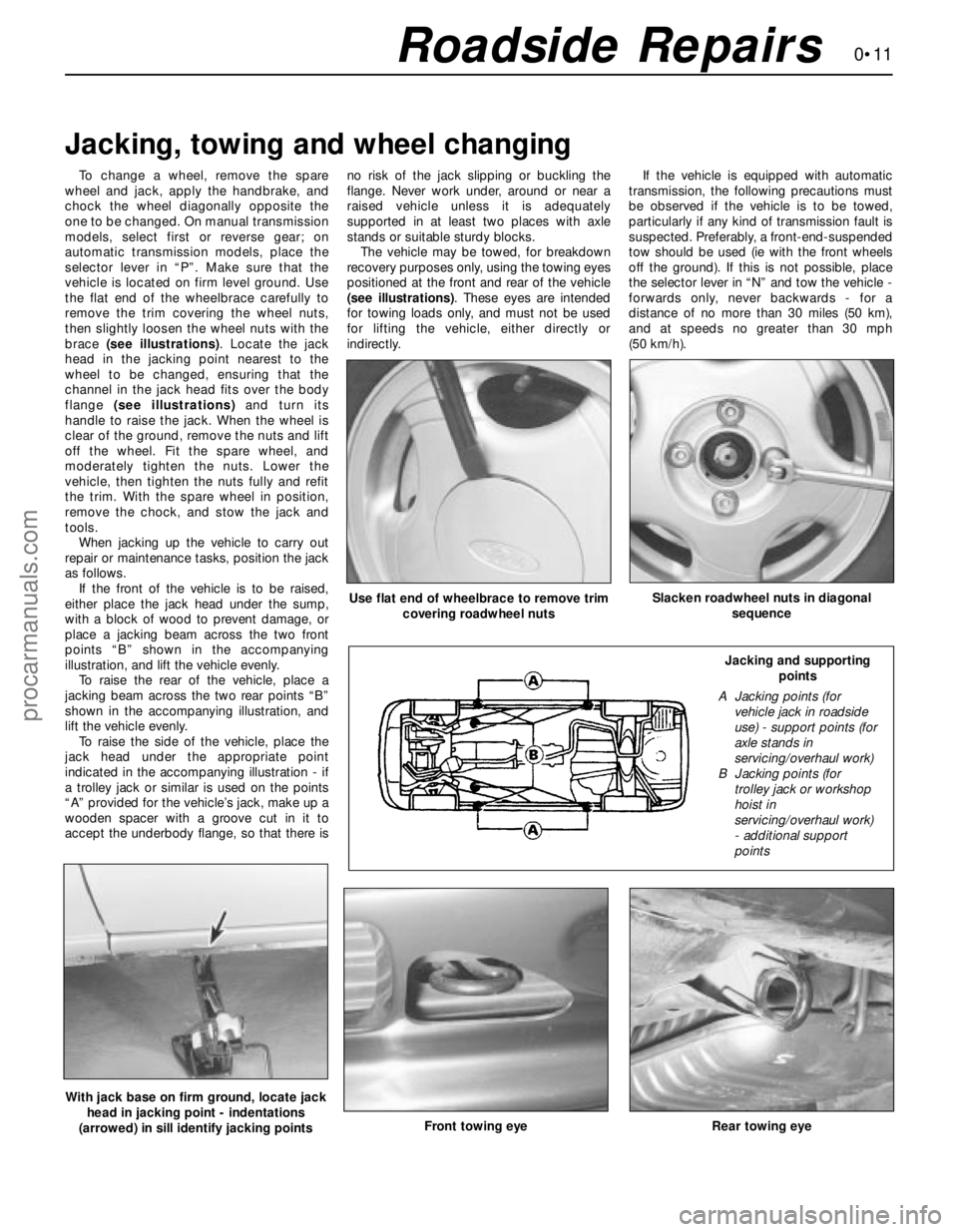
brace (see illustrations). Locate the jack
head in the jacking point nearest to the
wheel to be changed, ensuring that the
channel in the jack head fits over the body
flange (see illustrations)and turn its
handle to raise the jack. When the wheel is
clear of the ground, remove the nuts and lift
off the wheel. Fit the spare wheel, and
moderately tighten the nuts. Lower the
vehicle, then tighten the nuts fully and refit
the trim. With the spare wheel in position,
remove the chock, and stow the jack and
tools.
When jacking up the vehicle to carry out
repair or maintenance tasks, position the jack
as follows.
If the front of the vehicle is to be raised,
either place the jack head under the sump,
with a block of wood to prevent damage, or
place a jacking beam across the two front
points “B” shown in the accompanying
illustration, and lift the vehicle evenly.
To raise the rear of the vehicle, place a
jacking beam across the two rear points “B”
shown in the accompanying illustration, and
lift the vehicle evenly.
To raise the side of the vehicle, place the
jack head under the appropriate point
indicated in the accompanying illustration - if
a trolley jack or similar is used on the points
“A” provided for the vehicle’s jack, make up a
wooden spacer with a groove cut in it to
accept the underbody flange, so that there isno risk of the jack slipping or buckling the
flange. Never work under, around or near a
raised vehicle unless it is adequately
supported in at least two places with axle
stands or suitable sturdy blocks.
The vehicle may be towed, for breakdown
recovery purposes only, using the towing eyes
positioned at the front and rear of the vehicle
(see illustrations). These eyes are intended
for towing loads only, and must not be used
for lifting the vehicle, either directly or
indirectly.If the vehicle is equipped with automatic
transmission, the following precautions must
be observed if the vehicle is to be towed,
particularly if any kind of transmission fault is
suspected. Preferably, a front-end-suspended
tow should be used (ie with the front wheels
off the ground). If this is not possible, place
the selector lever in “N” and tow the vehicle -
forwards only, never backwards - for a
distance of no more than 30 miles (50 km),
and at speeds no greater than 30 mph
(50 km/h).
Jacking, towing and wheel changing
Front towing eyeRear towing eye
Use flat end of wheelbrace to remove trim
covering roadwheel nutsSlacken roadwheel nuts in diagonal
sequence
With jack base on firm ground, locate jack
head in jacking point - indentations
(arrowed) in sill identify jacking points
Jacking and supporting
points
A Jacking points (for
vehicle jack in roadside
use) - support points (for
axle stands in
servicing/overhaul work)
B Jacking points (for
trolley jack or workshop
hoist in
servicing/overhaul work)
- additional support
points
procarmanuals.com
Page 17 of 279
Ford Mondeo maintenance schedule
1•3
1
Maintenance schedule
The manufacturer’s recommended maintenance schedule for these
vehicles is as described below - note that the schedule starts from the
vehicle’s date of registration. These are the minimum maintenance
intervals recommended by the factory for Mondeos driven daily, but
subjected only to “normal” use. If you wish to keep your vehicle in
peak condition at all times, you may wish to perform some of these
procedures even more often. Because frequent maintenance
enhances the efficiency, performance and resale value of your vehicle,
we encourage you to do so. If your usage is not “normal”, shorter
intervals are also recommended - the most important examples of
these are noted in the schedule. These shorter intervals apply
particularly if you drive in dusty areas, tow a caravan or trailer, sit with
the engine idling or drive at low speeds for extended periods (ie, in
heavy traffic), or drive for short distances (less than four miles) in
below-freezing temperatures.
When your vehicle is new, it should be serviced by a Ford dealer
service department to protect the factory warranty. In many cases, the
initial maintenance check is done at no cost to the owner. Note that
this first free service (carried out by the selling dealer 1500 miles or 3
months after delivery), although an important check for a new vehicle,
is not part of the regular maintenance schedule, and is therefore not
mentioned here.
Weekly checks
m mCheck the engine oil level, and top-up if necessary
(Section 3)
m mCheck the brake fluid level, and top-up if necessary
(Section 3). If repeated topping-up is required, check the
system for leaks or damage at the earliest possible
opportunity (Sections 12 and 22)
m mCheck the windscreen/tailgate washer fluid level, and top-
up if necessary (Section 3)
m mCheck the tyre pressures, including the spare (Section 4)
m mVisually check the tyres for excessive tread wear, or
damage (Section 4)
m mCheck the operation of all (exterior and interior) lights and
the horn, wipers and windscreen/tailgate washer system
(Sections 6 and 8). Renew any blown bulbs (Chapter 12),
and clean the lenses of all exterior lights
Monthly checks
m mCheck the coolant level, and top-up if necessary (Sec-
tion 3)
m mCheck the battery electrolyte level, where applicable
(Section 3)
m mCheck the power steering fluid level, and top-up if
necessary (Section 5)
m mVisually check all reservoirs, hoses and pipes for leakage
(Section 12)
m mCheck the operation of the air conditioning system
(Section 14)
m mCheck the operation of the handbrake (Section 23)
m mCheck the aim of the windscreen/tailgate/headlight
washer jets, correcting them if required (Section 6)
m mCheck the condition of the wiper blades, renewing them if
worn or no longer effective - note that the manufacturer
recommends renewing the blades as a safety precaution,
irrespective of their apparent condition, at least once a
year (Section 6)
Every 10 000 miles or 12 months,
whichever occurs first
Note:If the vehicle is used regularly for very short (less than
10 miles), stop/go journeys, the oil and filter should be renewed
between services (ie, every 5000 miles/6 months).
m mCheck the electrical system (Section 8)
m mCheck the battery (Section 9)
m mCheck the seat belts (Section 10)
m mCheck the auxiliary drivebelt (Section 11)
m mCheck for fluid leaks and hose condition (Section 12)
m mCheck the condition of all wiring (Section 13)
m mCheck all air conditioning components (Section 14)
m mChange the engine oil and filter (Section 15)
m mCheck the manual transmission oil level (Section 16)
m mCheck the adjustment of the clutch pedal (Section 17)
m mLubricate the automatic transmission linkage (Section 18)
m mCheck the steering, suspension and wheels (Section 19)
m mCheck the driveshaft gaiters and CV joints (Section 20)
m mCheck the exhaust system (Section 21)
m mCheck the underbody, and all fuel/brake lines (Section 22)
m mCheck the brake system (Section 23)
m mCheck and lubricate the doors and bonnet (Section 24)
m mCheck the security of all roadwheel nuts (Section 25)
m mRoad test (Section 26). Check the level of the automatic
transmission fluid with the engine still hot, after the road
test (Section 7)
Every 20 000 miles or 2 years,
whichever occurs first
Carry out all operations listed above, plus the following:
m mRenew the ventilation system pollen filter (Section 27)
m mRenew the coolant (Sections 2 and 28)
Every 30 000 miles or 3 years,
whichever occurs first
Carry out all operations listed above, plus the following:
m mRenew the air filter element (Section 29). Note that this
task must be carried out at more frequent intervals if the
vehicle is used in dusty or polluted conditions
m mCheck the Positive Crankcase Ventilation (PCV) system,
and clean the filter (Section 30)
m mRenew the spark plugs (Section 31)
Every 60 000 miles
Carry out all operations listed above, plus the following:
m
mRenew the timing belt (Section 32)
m mRenew the fuel filter (Section 33)
Every 3 years
(regardless of mileage)
m mRenew the brake fluid (Section 34)
procarmanuals.com
Page 24 of 279
the tyre to cause deflation. If removal of a nail
reveals that the tyre has been punctured, refit
the nail, so that its point of penetration is
marked. Then immediately change the wheel,
and have the tyre repaired by a tyre dealer. Do
not drive on a tyre in such a condition. If in any
doubt as to the possible consequences of any
damage found, consult your local tyre dealer
for advice.
8General tyre wear is influenced to a large
degree by driving style - harsh braking and
acceleration, or fast cornering, will all produce
more rapid tyre wear. Interchanging of tyres
may result in more even wear; however, it is
worth bearing in mind that if this is completely
effective, the added expense is incurred of
replacing simultaneously a complete set of
tyres, which may prove financially restrictive
for many owners.
9Front tyres may wear unevenly as a result of
wheel misalignment. The front wheels should
always be correctly aligned according to the
settings specified by the vehicle
manufacturer.10Don’t forget to check the spare tyre for
condition and pressure.
11Legal restrictions apply to many aspects
of tyre fitting and usage, and in the UK this
information is contained in the Motor Vehicle
Construction and Use Regulations. It is
suggested that a copy of these regulations is
obtained from your local police, if in doubt as
to current legal requirements with regard to
tyre type and condition, minimum tread depth,
etc.
1The power steering fluid reservoir is located
on the right-hand rear corner of the engine
compartment.
2For the fluid level check, the power steering
system should be at its normal operating
temperature, so it is best to carry out the
check after a run.
3Position the vehicle on level ground, withthe front wheels pointing straight ahead, and
switch off the engine.
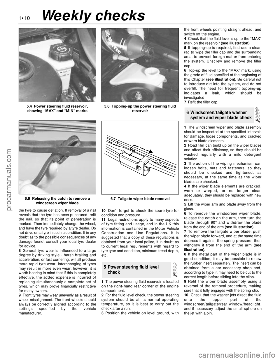
4Check that the fluid level is up to the “MAX”
mark on the reservoir (see illustration).
5If topping-up is required, first use a clean
rag to wipe the filler cap and the surrounding
area, to prevent foreign matter from entering
the system. Unscrew and remove the filler
cap.
6Top-up the level to the “MAX” mark, using
the grade of fluid specified at the beginning of
this Chapter (see illustration). Be careful not
to introduce dirt into the system, and do not
overfill. The need for frequent topping-up
indicates a leak, which should be
investigated.
7Refit the filler cap.
1The windscreen wiper and blade assembly
should be inspected at the specified intervals
for damage, loose components, and cracked
or worn blade elements.
2Road film can build up on the wiper blades
and affect their efficiency, so they should be
washed regularly with a mild detergent
solution.
3The action of the wiping mechanism can
loosen bolts, nuts and fasteners, so they
should be checked and tightened, as
necessary, at the same time as the wiper
blades are checked.
4If the wiper blade elements are cracked,
worn or warped, or no longer clean
adequately, they should be replaced with new
ones.
5Lift the wiper arm and blade away from the
glass.
6To remove the windscreen wiper blade,
release the catch on the arm, then turn the
blade through 90° and withdraw the blade
from the end of the arm (see illustration).
7To remove the tailgate wiper blade, push
the wiper blade forward, and at the same time
depress it against the spring pressure, then
withdraw it from the end of the arm (see
illustration).
8If the metal part of the wiper blade is in
good condition, it may be possible to renew
the rubber insert separately. The insert can be
obtained from a car accessory shop and,
according to type, it may need to be cut to the
correct length before sliding into the clips.
9Refit the wiper blade assembly using a
reversal of the removal procedure, making
sure that it fully engages with the spring clip.
10Check that the washer jets direct the fluid
onto the upper part of the
windscreen/tailgate/rear window/headlight,
and if necessary adjust the small sphere on
the jet with a pin.
6 Windscreen/tailgate washer
system and wiper blade check
5 Power steering fluid level
check
1•10
5.4 Power steering fluid reservoir,
showing “MAX” and “MIN” marks5.6 Topping-up the power steering fluid
reservoir
6.7 Tailgate wiper blade removal6.6 Releasing the catch to remove a
windscreen wiper blade
Weekly checks
procarmanuals.com
Page 127 of 279
bracket. Note that on Saloon and Hatchback
models, the pin is at the bottom of the caliper,
whereas on Estate models, it is at the top.
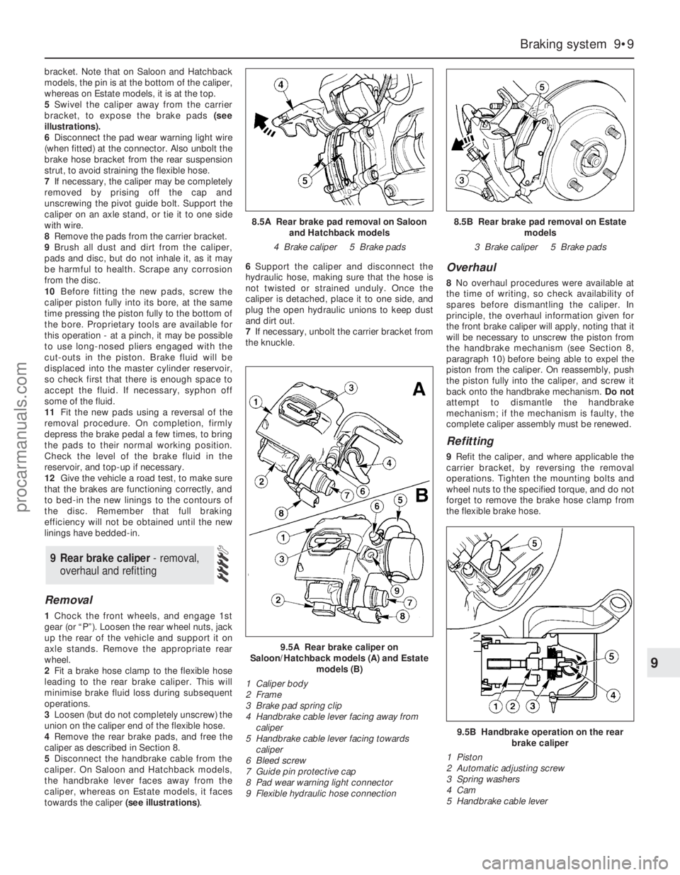
5Swivel the caliper away from the carrier
bracket, to expose the brake pads (see
illustrations).
6Disconnect the pad wear warning light wire
(when fitted) at the connector. Also unbolt the
brake hose bracket from the rear suspension
strut, to avoid straining the flexible hose.
7If necessary, the caliper may be completely
removed by prising off the cap and
unscrewing the pivot guide bolt. Support the
caliper on an axle stand, or tie it to one side
with wire.
8Remove the pads from the carrier bracket.
9Brush all dust and dirt from the caliper,
pads and disc, but do not inhale it, as it may
be harmful to health. Scrape any corrosion
from the disc.
10Before fitting the new pads, screw the
caliper piston fully into its bore, at the same
time pressing the piston fully to the bottom of
the bore. Proprietary tools are available for
this operation - at a pinch, it may be possible
to use long-nosed pliers engaged with the
cut-outs in the piston. Brake fluid will be
displaced into the master cylinder reservoir,
so check first that there is enough space to
accept the fluid. If necessary, syphon off
some of the fluid.
11Fit the new pads using a reversal of the
removal procedure. On completion, firmly
depress the brake pedal a few times, to bring
the pads to their normal working position.
Check the level of the brake fluid in the
reservoir, and top-up if necessary.
12Give the vehicle a road test, to make sure
that the brakes are functioning correctly, and
to bed-in the new linings to the contours of
the disc. Remember that full braking
efficiency will not be obtained until the new
linings have bedded-in.
Removal
1Chock the front wheels, and engage 1st
gear (or “P”). Loosen the rear wheel nuts, jack
up the rear of the vehicle and support it on
axle stands. Remove the appropriate rear
wheel.
2Fit a brake hose clamp to the flexible hose
leading to the rear brake caliper. This will
minimise brake fluid loss during subsequent
operations.
3Loosen (but do not completely unscrew) the
union on the caliper end of the flexible hose.
4Remove the rear brake pads, and free the
caliper as described in Section 8.
5Disconnect the handbrake cable from the
caliper. On Saloon and Hatchback models,
the handbrake lever faces away from the
caliper, whereas on Estate models, it faces
towards the caliper (see illustrations).6Support the caliper and disconnect the
hydraulic hose, making sure that the hose is
not twisted or strained unduly. Once the
caliper is detached, place it to one side, and
plug the open hydraulic unions to keep dust
and dirt out.
7If necessary, unbolt the carrier bracket from
the knuckle.
Overhaul
8No overhaul procedures were available at
the time of writing, so check availability of
spares before dismantling the caliper. In
principle, the overhaul information given for
the front brake caliper will apply, noting that it
will be necessary to unscrew the piston from
the handbrake mechanism (see Section 8,
paragraph 10) before being able to expel the
piston from the caliper. On reassembly, push
the piston fully into the caliper, and screw it
back onto the handbrake mechanism. Do not
attempt to dismantle the handbrake
mechanism; if the mechanism is faulty, the
complete caliper assembly must be renewed.
Refitting
9Refit the caliper, and where applicable the
carrier bracket, by reversing the removal
operations. Tighten the mounting bolts and
wheel nuts to the specified torque, and do not
forget to remove the brake hose clamp from
the flexible brake hose.
9 Rear brake caliper - removal,
overhaul and refitting
Braking system 9•9
9
9.5A Rear brake caliper on
Saloon/Hatchback models (A) and Estate
models (B)
1 Caliper body
2 Frame
3 Brake pad spring clip
4 Handbrake cable lever facing away from
caliper
5 Handbrake cable lever facing towards
caliper
6 Bleed screw
7 Guide pin protective cap
8 Pad wear warning light connector
9 Flexible hydraulic hose connection
9.5B Handbrake operation on the rear
brake caliper
1 Piston
2 Automatic adjusting screw
3 Spring washers
4 Cam
5 Handbrake cable lever
8.5A Rear brake pad removal on Saloon
and Hatchback models
4 Brake caliper 5 Brake pads8.5B Rear brake pad removal on Estate
models
3 Brake caliper 5 Brake pads
procarmanuals.com
Page 132 of 279
Note:If any part of the ABS hydraulic unit is
defective, it must be renewed as an assembly.
Apart from the relay box (Section 22),
individual spare parts are not available.
Removal
1Remove both pressure-control relief valves
as described in Section 19.
2Identify the location of the remaining brake
hydraulic pipes on the ABS hydraulic unit,
then unscrew the union nuts and pull out the
pipes. Carefully bend the pipes away from the
hydraulic unit, to allow the unit to be removed.
3Disconnect the multi-plugs from the
hydraulic unit. To disconnect the main 22-pin
multi-plug, push the locktab, then swivel the
multi-plug outwards and unhook it.
Right-hand drive models
4Have an assistant hold the brake pedal
depressed, then extract the spring clip and
remove the clevis pin securing the servo unit
pushrod to the pedal cross-link arm.
5Remove the vacuum servo unit from the
engine compartment.
Left-hand drive models
6Unscrew the nut securing the pedal
trunnion to the servo unit pushrod inside the
passenger compartment. The nut is located
near the top of the pedal, and is accessible
through an access hole. For improved access,
remove the lower facia panel first.
7Remove the vacuum servo unit, together
with the pushrod, from the engine
compartment. Take care not to damage the
rubber grommet in the bulkhead.
All models
8Unscrew the pump mounting nut.
9Raise the left-hand side of the ABS
hydraulic unit, then swivel the unit out of the
right-hand mounting. Take care not to lose the
bracket studs and insulator ring.
Refitting
10Locate the insulator ring on the pump
end, and fit the stud cap to the insulator ring.
11Lower the ABS hydraulic unit into
position, right-hand end first.
12Fit the right-hand bracket studs onto the
insulators.
13Lower the left-hand end of the ABS
hydraulic unit onto the bracket, then fit and
tighten the pump mounting nut.
Left-hand drive models
14Locate the vacuum servo unit and
pushrod on the bulkhead bracket, taking care
not to damage the rubber grommet.
15Insert the pushrod in the pedal trunnion,
and tighten the nut.
16Refit the lower facia panel if it was
removed.
Right-hand drive models
17Locate the vacuum servo unit and
pushrod on the bulkhead bracket.
18Refit the clevis pin and spring clip
securing the servo unit pushrod to the pedal
cross-link arm.
All models
19Reconnect the multi-plugs to the
hydraulic unit.
20Reconnect the brake pipes to the
hydraulic unit, and tighten the union nuts.
21Refit both pressure-control relief valves,
with reference to Section 20.
Testing
1Checking of the sensors is done before
removal, connecting a voltmeter to the
disconnected sensor multi-plug. Using an
analogue (moving coil) meter is not practical,
since the meter does not respond quickly
enough. A digital meter having an AC facility
may be used to check that the sensor is
operating correctly. To do this, raise the
relevant wheel then disconnect the wiring to
the ABS sensor and connect the meter to it.
Spin the wheel and check that the output
voltage is between 1.5 and 2.0 volts,
depending on how fast the wheel is spun.
Alternatively, an oscilloscope may be used to
check the output of the sensor - an alternating
current will be traced on the screen, of
magnitude depending on the speed of the
rotating wheel.
2If the sensor output is low or zero, renew
the sensor.
Removal
Front wheel sensor
3Apply the handbrake, jack up the front of
the vehicle and support it on axle stands.
Remove the relevant wheel.
4Unscrew the sensor mounting bolt located
on the steering knuckle, and withdraw the
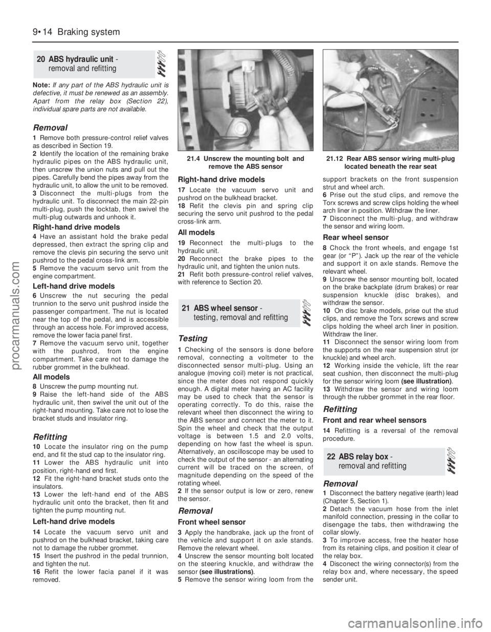
sensor (see illustrations).
5Remove the sensor wiring loom from thesupport brackets on the front suspension
strut and wheel arch.
6Prise out the stud clips, and remove the
Torx screws and screw clips holding the wheel
arch liner in position. Withdraw the liner.
7Disconnect the multi-plug, and withdraw
the sensor and wiring loom.
Rear wheel sensor
8Chock the front wheels, and engage 1st
gear (or “P”). Jack up the rear of the vehicle
and support it on axle stands. Remove the
relevant wheel.
9Unscrew the sensor mounting bolt, located
on the brake backplate (drum brakes) or rear
suspension knuckle (disc brakes), and
withdraw the sensor.
10On disc brake models, prise out the stud
clips, and remove the Torx screws and screw
clips holding the wheel arch liner in position.
Withdraw the liner.
11Disconnect the sensor wiring loom from
the supports on the rear suspension strut (or
knuckle) and wheel arch.
12Working inside the vehicle, lift the rear
seat cushion, then disconnect the multi-plug
for the sensor wiring loom (see illustration).
13Withdraw the sensor and wiring loom
through the rubber grommet in the rear floor.
Refitting
Front and rear wheel sensors
14Refitting is a reversal of the removal
procedure.
Removal
1Disconnect the battery negative (earth) lead
(Chapter 5, Section 1).
2Detach the vacuum hose from the inlet
manifold connection, pressing in the collar to
disengage the tabs, then withdrawing the
collar slowly.
3To improve access, free the heater hose
from its retaining clips, and position it clear of
the relay box.
4Disconect the wiring connector(s) from the
relay box and, where necessary, the speed
sender unit.
22 ABS relay box -
removal and refitting
21 ABS wheel sensor -
testing, removal and refitting
20 ABS hydraulic unit -
removal and refitting
9•14 Braking system
21.4 Unscrew the mounting bolt and
remove the ABS sensor21.12 Rear ABS sensor wiring multi-plug
located beneath the rear seat
procarmanuals.com
Page 278 of 279
REF•19Index
Oil pressure warning light switch - 2A•22
Oil pump - 2A•21
Oil seals - 2A•13, 2A•22, 7A•2, 7B•3, REF•4
Oil separator - 6•19
Open-circuit - 12•4
Overcooling - REF•8
Overhead console - 11•22
Overheating - REF•8
Oxygen sensor - 6•11, 6•12, 6•13
P
Pads - 9•3, 9•8
Pedals - 1•17, 4•5, 8•3, 9•10, 9•11
Piston rings - 2B•19
Pistons - 2B•12, 2B•17, 2B•21, 2B•22
Pitching and/or rolling around corners -
REF•11
Plastic components - 11•4
Plenum chamber - 4•3
Poisonous or irritant substances - 0•5
Pollen filter - 1•20, 3•8
Position sensor - 5•4, 6•10, 6•11, 6•12
Positive Crankcase Ventilation (PCV)
system - 1•23, 6•18, 6•19
Power steering - 1•8, 1•10, 6•11, 6•12,
6•13, 10•20, 10•21, 10•22
Power steering fluid - 1•2
Pressure-control relief valve - 9•13
Pressure-cycling and pressure-regulating
switches - 3•10
Project vehicles - 0•4
Pulse-air - 6•17, 6•18
Purge solenoid valve - 6•14
R
Radiator - 3•4, 3•5
Radiator grille - 11•5
Radio - 12•21, 12•22
Radio aerial - 12•22
Reading light - 12•11
Rear light cluster - 12•9, 12•13
Rear window - 12•8, 12•21
Relays - 12•5
Repair procedures - REF•4
Resonator (engine compartment) - 4•3
Respraying - 11•3
Reversing light switch - 7A•3
Road test - 1•20
Roadwheels - 1•17, 1•18, 1•20
Roll-over valves - 4•8
Routine maintenance and servicing- 1•1et
seq
Rubber gaiters- 1•18, 8•7, 8•9, 10•21
Rust holes in bodywork - 11•3
S
Safety first! - 0•5
Scalding - 0•5
Scratches in bodywork - 11•3
Screw threads and fastenings - REF•4
Seat belts - 0•8, 1•13, 11•19, 11•20Seats - 0•8, 11•18, 12•8
Selector assembly - 7B•2
Selector cable - 7B•2
Selector lever position sensor - 7B•2
Selector panel illumination - 12•11
Service indicator - 12•17, 12•18
Servo unit - 9•12, 9•13
Shock absorbers - 0•8, 0•9, 10•14
Shoes - 9•6
Short-circuit - 12•4
Sidelight - 12•9
Solenoid renewal - 5•8
Spare parts - REF•5
Spark plugs - 1•23
Speakers - 12•22
Speed control - 12•20
Speed sensor - 6•11, 6•12, 6•13
Speedometer - 7A•2, 7A•3, 7B•2, 7B•3,
12•15
Springs - 0•9
Starter motor - 5•7
Starter motor fault - REF•7
Starting system - 5•6
Steering - 0•7, 0•8, 0•9, 1•17, 1•20
Steering angles - 10•22
Steering column - 10•18, 10•20
Steering fault - REF•11
Steering knuckle - 10•5
Steering wheel - 10•17
Stop-light switch - 9•15
Striker - 11•13
Struts - 10•6, 10•7, 10•10, 10•12
Sump - 2A•19
Sun visor - 11•20
Sunroof - 11•18, 12•7
Suspension and steering systems- 0•8,
0•9, 1•17, 1•18, 1•20, 10•1et seq
Suspension and steering systems fault
finding - REF•11
Switches - 2A•22, 3•4, 3•5, 3•10, 4•8-
6•11, 6•12, 6•13, 7A•3, 9•15, 11•17,
12•6, 12•7, 12•8, 12•11, 12•18, 12•20
T
Tailgate - 1•8, 1•10, 11•15, 11•16, 12•17,
12•20, REF•12
Tappets - 2A•14
TCS inhibitor switch - 9•15
TCS throttle actuator - 9•15
Temperature gauge fault - REF•12
Thermostat - 3•3, 3•4
Throttle actuator - 9•15
Throttle housing - 4•9
Throttle potentiometer - 6•11, 6•13
Tie-bar - 10•13, 10•16
Timer module - 12•5
Timing - 5•4, 6•10
Timing belt - 1•26, 2A•10, 2A•13
Tools - REF•1, REF•3, REF•4
Top Dead Centre (TDC) for No 1 piston -
2A•6
Towing - 0•11
Track rod end - 10•22Traction Control System - 9•15, 12•7
Transmission- 1•11, 1•17, 2A•24, 2B•3,
2B•4, 7A•1 et seq, 7B•1 et seq, 12•11
Trim mouldings - 11•17
Trim panels - 11•6, 11•20
Trip computer - 12•17
Tyre wear - REF•11
Tyres - 0•10, 1•8
U
Underbody check - 1•19
Upper suspension arm - 10•16
V
Vacuum hoses - 1•15
Vacuum servo unit - 9•12, 9•13
Valve clearances - 2A•5
Valves - 2B•10, 2B•11
Vehicle identification - 0•8, REF•5
Vehicle pulls to one side - REF•10, REF•11
Vehicle speed sensor - 6•11, 6•12, 6•13
Ventilation system - 1•20, 3•7
Voltage regulator - 5•6
W
Warning lights - 12•11
Warning system - 12•17
Washer jets fault - REF•12
Washer nozzle - 12•21
Washer pump fault - REF•12
Washer reservoir and pump - 12•20
Washer system - 1•8, 1•10, 12•18, 12•20
Water pump - 3•6
Weights - 0•6
Wheel alignment - 10•22
Wheel arch liner - 11•24
Wheel bearings - 0•9
Wheel changing - 0•11
Wheel cylinders - 9•8
Wheel sensors - 9•14
Wheel wobble - REF•11
Wheels - 0•10, 1•17, 1•18, 1•20
Wheels locking - REF•11
Window glass - 11•8
Window regulator - 11•9
Windows - 11•17, 12•7, 12•8, 12•21,
REF•12
Windscreen - 0•7, 1•8, 1•10, 11•17, 12•6,
12•8, 12•16, 12•20, 12•21, REF•12
Wiper arms - 12•16
Wiper blade - 1•10
Wiper blade fault - REF•12
Wiper motor - 12•16, 12•17
Wipers - 12•6
Wiper fault - REF•12
Wiring - 1•15
Wiring diagrams- 12•23et seq
Working facilities - REF•3
procarmanuals.com