1993 FORD MONDEO driver seat adjustment
[x] Cancel search: driver seat adjustmentPage 7 of 279

0•7
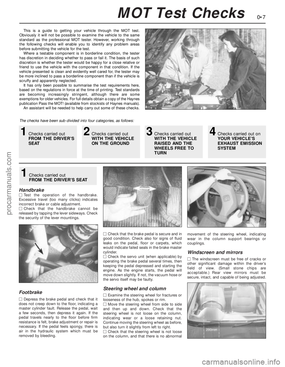
This is a guide to getting your vehicle through the MOT test.
Obviously it will not be possible to examine the vehicle to the same
standard as the professional MOT tester. However, working through
the following checks will enable you to identify any problem areas
before submitting the vehicle for the test.
Where a testable component is in borderline condition, the tester
has discretion in deciding whether to pass or fail it. The basis of such
discretion is whether the tester would be happy for a close relative or
friend to use the vehicle with the component in that condition. If the
vehicle presented is clean and evidently well cared for, the tester may
be more inclined to pass a borderline component than if the vehicle is
scruffy and apparently neglected.
It has only been possible to summarise the test requirements here,
based on the regulations in force at the time of printing. Test standards
are becoming increasingly stringent, although there are some
exemptions for older vehicles. For full details obtain a copy of the Haynes
publication Pass the MOT! (available from stockists of Haynes manuals).
An assistant will be needed to help carry out some of these checks.
The checks have been sub-divided into four categories, as follows:
HandbrakeMTest the operation of the handbrake.
Excessive travel (too many clicks) indicates
incorrect brake or cable adjustment.
MCheck that the handbrake cannot be
released by tapping the lever sideways. Check
the security of the lever mountings.
Footbrake
MDepress the brake pedal and check that it
does not creep down to the floor, indicating a
master cylinder fault. Release the pedal, wait
a few seconds, then depress it again. If the
pedal travels nearly to the floor before firm
resistance is felt, brake adjustment or repair is
necessary. If the pedal feels spongy, there is
air in the hydraulic system which must be
removed by bleeding.MCheck that the brake pedal is secure and in
good condition. Check also for signs of fluid
leaks on the pedal, floor or carpets, which
would indicate failed seals in the brake master
cylinder.
MCheck the servo unit (when applicable) by
operating the brake pedal several times, then
keeping the pedal depressed and starting the
engine. As the engine starts, the pedal will
move down slightly. If not, the vacuum hose or
the servo itself may be faulty.
Steering wheel and column
MExamine the steering wheel for fractures or
looseness of the hub, spokes or rim.
MMove the steering wheel from side to side
and then up and down. Check that the
steering wheel is not loose on the column,
indicating wear or a loose retaining nut.
Continue moving the steering wheel as before,
but also turn it slightly from left to right.
MCheck that the steering wheel is not loose
on the column, and that there is no abnormalmovement of the steering wheel, indicating
wear in the column support bearings or
couplings.
Windscreen and mirrors
MThe windscreen must be free of cracks or
other significant damage within the driver’s
field of view. (Small stone chips are
acceptable.) Rear view mirrors must be
secure, intact, and capable of being adjusted.
1Checks carried out
FROM THE DRIVER’S SEAT
MOT Test Checks
1Checks carried out
FROM THE DRIVER’S
SEAT2Checks carried out
WITH THE VEHICLE
ON THE GROUND3Checks carried out
WITH THE VEHICLE
RAISED AND THE
WHEELS FREE TO
TURN4Checks carried out on
YOUR VEHICLE’S
EXHAUST EMISSION
SYSTEM
procarmanuals.com
Page 202 of 279

Chapter 12 Body electrical system
Air bag clock spring - removal and refitting . . . . . . . . . . . . . . . . . . . 30
Air bag control module - removal and refitting . . . . . . . . . . . . . . . . . 29
Air bag unit (driver’s side) - removal and refitting . . . . . . . . . . . . . . . 28
Anti-theft alarm system - general information . . . . . . . . . . . . . . . . . . 20
Auxiliary warning system - general information and
component renewal . . . . . . . . . . . . . . . . . . . . . . . . . . . . . . . . . . . . 19
Battery - check, maintenance and charging . . . . . . . . See Chapter 1
Battery - removal and refitting . . . . . . . . . . . . . . . . . . . See Chapter 5
Bulbs (exterior lights) - renewal . . . . . . . . . . . . . . . . . . . . . . . . . . . . . 5
Bulbs (interior lights) - renewal . . . . . . . . . . . . . . . . . . . . . . . . . . . . . 6
Clock - removal and refitting . . . . . . . . . . . . . . . . . . . . . . . . . . . . . . . 13
Compact disc player - removal and refitting . . . . . . . . . . . . . . . . . . . 25
Cruise control system - general information . . . . . . . . . . . . . . . . . . . 21
Electrical fault finding - general information . . . . . . . . . . . . . . . . . . . 2
Electrical system check . . . . . . . . . . . . . . . . . . . . . . . . See Chapter 1
Exterior light units - removal and refitting . . . . . . . . . . . . . . . . . . . . . 7
Fuses, relays and timer module - testing and renewal . . . . . . . . . . . 3
General information . . . . . . . . . . . . . . . . . . . . . . . . . . . . . . . . . . . . . . 1
Headlight beam alignment - checking and adjustment . . . . . . . . . . 8
Headlight levelling motor - removal and refitting . . . . . . . . . . . . . . . 9Horn - removal and refitting . . . . . . . . . . . . . . . . . . . . . . . . . . . . . . . 14
Instrument panel - removal and refitting . . . . . . . . . . . . . . . . . . . . . . 10
Instrument panel components - removal and refitting . . . . . . . . . . . 11
Radio aerial - removal and refitting . . . . . . . . . . . . . . . . . . . . . . . . . . 27
Radio/cassette player - coding, removal and refitting . . . . . . . . . . . 23
Radio/cassette player power amplifier - removal and refitting . . . . . 24
Speakers - removal and refitting . . . . . . . . . . . . . . . . . . . . . . . . . . . . 26
Speedometer drive cable - removal and refitting . . . . . . . . . . . . . . . 12
Stop-light switch - removal and refitting . . . . . . . . . . . See Chapter 9
Switches - removal and refitting . . . . . . . . . . . . . . . . . . . . . . . . . . . . 4
Tailgate wiper motor assembly - removal and refitting . . . . . . . . . . . 17
TCS inhibition switch - removal and refitting . . . . . . . . See Chapter 9
Trip computer module - removal and refitting . . . . . . . . . . . . . . . . . 18
Windscreen/tailgate washer system and wiper blade
check . . . . . . . . . . . . . . . . . . . . . . . . . . . . . . . . . . . . See Chapter 1
Windscreen/tailgate washer system components - removal
and refitting . . . . . . . . . . . . . . . . . . . . . . . . . . . . . . . . . . . . . . . . . . 22
Windscreen wiper motor and linkage - removal and refitting . . . . . . 16
Wiper arms - removal and refitting . . . . . . . . . . . . . . . . . . . . . . . . . . 15
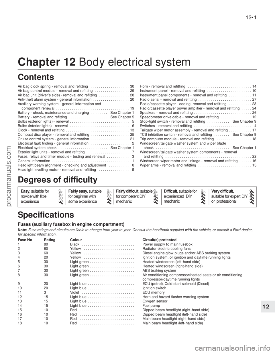
Fuses (auxiliary fusebox in engine compartment)
Note:Fuse ratings and circuits are liable to change from year to year. Consult the handbook supplied with the vehicle, or consult a Ford dealer,
for specific information.
Fuse No Rating Colour Circuit(s) protected
1 80 Black . . . . . . . . . . . . . . . . . . . . . . . . . . Power supply to main fusebox
2 60 Yellow . . . . . . . . . . . . . . . . . . . . . . . . . Radiator electric cooling fans
3 60 Yellow . . . . . . . . . . . . . . . . . . . . . . . . . Diesel engine glow plugs and/or ABS braking system
4 20 Yellow . . . . . . . . . . . . . . . . . . . . . . . . . Ignition system, or ignition and daytime running lights
5 30 Light green . . . . . . . . . . . . . . . . . . . . . . Heated windscreen (left-hand side)
6 30 Light green . . . . . . . . . . . . . . . . . . . . . . Heated windscreen (right-hand side)
7 30 Light green . . . . . . . . . . . . . . . . . . . . . . ABS braking system
8 30 Light green . . . . . . . . . . . . . . . . . . . . . . Air conditioning compressor/heated seats or air conditioning
compressor/daytime running lights
9 20 Light blue . . . . . . . . . . . . . . . . . . . . . . . ECU (petrol), Cold start solenoid (Diesel)
10 20 Light blue . . . . . . . . . . . . . . . . . . . . . . . Ignition switch
11 3 Violet . . . . . . . . . . . . . . . . . . . . . . . . . . ECU memory
12 15 Light blue . . . . . . . . . . . . . . . . . . . . . . . Horn and hazard flasher warning system
13 15 Light blue . . . . . . . . . . . . . . . . . . . . . . . Oxygen sensor
14 15 Light blue . . . . . . . . . . . . . . . . . . . . . . . Fuel pump
15 10 Red . . . . . . . . . . . . . . . . . . . . . . . . . . . Dipped beam headlight (right-hand side)
16 10 Red . . . . . . . . . . . . . . . . . . . . . . . . . . . Dipped beam headlight (left-hand side)
17 10 Red . . . . . . . . . . . . . . . . . . . . . . . . . . . Main beam headlight (right-hand side)
18 10 Red . . . . . . . . . . . . . . . . . . . . . . . . . . . Main beam headlight (left-hand side)
12•1
Easy,suitable for
novice with little
experienceFairly easy,suitable
for beginner with
some experienceFairly difficult,suitable
for competent DIY
mechanicDifficult,suitable for
experienced DIY
mechanicVery difficult,
suitable for expert DIY
or professional
Degrees of difficulty
Specifications Contents
12
procarmanuals.com
Page 214 of 279

located above the front direction indicator
(see illustration).
11Withdraw the front direction indicator light
unit.
12Rotate the bulbholder anti-clockwise, and
withdraw it from the light unit. Alternatively,
the wiring plug can be disconnected from the
bulbholder, leaving the bulb in position (see
illustration). Remove the light unit.
Foglight (front)
13Unscrew the cross-head screws securing
the front foglight unit to the valance, and
withdraw the light unit from the valance.
14Prise open the plastic clips, and remove
the rear cover from the light unit.
15Release the spring clips and withdraw the
bulb, then pull off the wiring connector.
Remove the foglight unit.
Rear light cluster
16With the tailgate or bootlid open, unhook
the parcel net (where fitted) from the rear of
the luggage compartment.
17On Saloon and Hatchback models,
remove the screws, release the clips, and
remove the trim panel from the rear cross
panel. On Estate models, it is sufficient to
open the flap.
18Remove the screws, and press the rear
light trim cover from the guides (where
applicable).
19Disconnect the wiring multi-plug.
20Unscrew the four mounting nuts, and
withdraw the light unit from the outside of the
vehicle (see illustrations).
Rear number plate light assembly
21Remove both number plate lights as
described in Section 5.
22With the tailgate or bootlid open, remove
the screws and withdraw the inner trim panel.
23Unscrew the nuts, and remove the outer
cover and number plate base from the
tailgate.
24Disconnect the multi-plug and remove the
light assembly.
Refitting
25Refitting of all the external light units is a
reversal of the removal procedure, noting the
following points:(a) When refitting the rubber seal on the
headlight unit, note that it has a tapered
seat.
(b) If one or both headlights have been
disturbed, have the beam alignment
checked as described in the next Section.
(c) When refitting the rear light cluster, check
the condition of the sealer on the body
panel, and if necessary renew it.
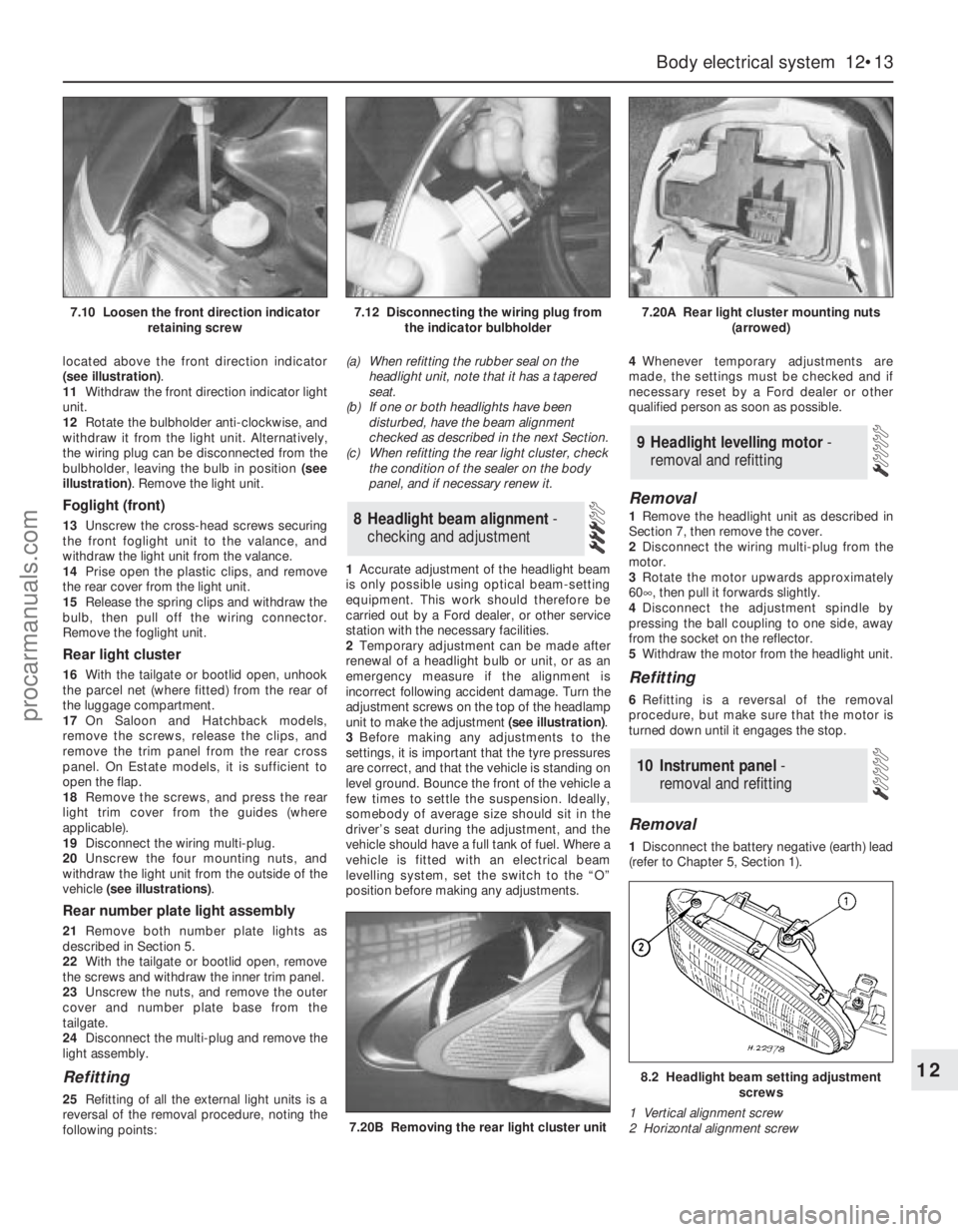
1Accurate adjustment of the headlight beam
is only possible using optical beam-setting
equipment. This work should therefore be
carried out by a Ford dealer, or other service
station with the necessary facilities.
2Temporary adjustment can be made after
renewal of a headlight bulb or unit, or as an
emergency measure if the alignment is
incorrect following accident damage. Turn the
adjustment screws on the top of the headlamp
unit to make the adjustment (see illustration).
3Before making any adjustments to the
settings, it is important that the tyre pressures
are correct, and that the vehicle is standing on
level ground. Bounce the front of the vehicle a
few times to settle the suspension. Ideally,
somebody of average size should sit in the
driver’s seat during the adjustment, and the
vehicle should have a full tank of fuel. Where a
vehicle is fitted with an electrical beam
levelling system, set the switch to the “O”
position before making any adjustments.4Whenever temporary adjustments are
made, the settings must be checked and if
necessary reset by a Ford dealer or other
qualified person as soon as possible.
Removal
1Remove the headlight unit as described in
Section 7, then remove the cover.
2Disconnect the wiring multi-plug from the
motor.
3Rotate the motor upwards approximately
60°, then pull it forwards slightly.
4Disconnect the adjustment spindle by
pressing the ball coupling to one side, away
from the socket on the reflector.
5Withdraw the motor from the headlight unit.
Refitting
6Refitting is a reversal of the removal
procedure, but make sure that the motor is
turned down until it engages the stop.
Removal
1Disconnect the battery negative (earth) lead
(refer to Chapter 5, Section 1).
10 Instrument panel -
removal and refitting
9 Headlight levelling motor -
removal and refitting
8 Headlight beam alignment-
checking and adjustment
Body electrical system 12•13
12
7.20B Removing the rear light cluster unit
8.2 Headlight beam setting adjustment
screws
1 Vertical alignment screw
2 Horizontal alignment screw
7.10 Loosen the front direction indicator
retaining screw7.12 Disconnecting the wiring plug from
the indicator bulbholder7.20A Rear light cluster mounting nuts
(arrowed)
procarmanuals.com
Page 256 of 279

Wiring diagrams 12•55
12
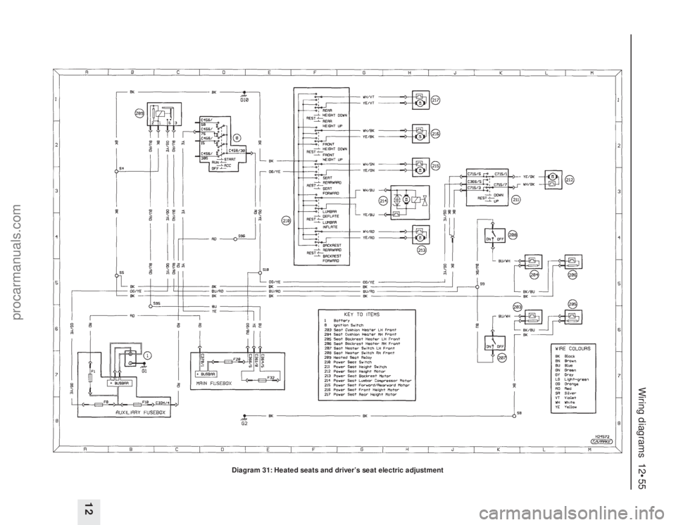
Diagram 31: Heated seats and driver’s seat electric adjustment
procarmanuals.com