1993 FORD MONDEO wheel alignment
[x] Cancel search: wheel alignmentPage 8 of 279
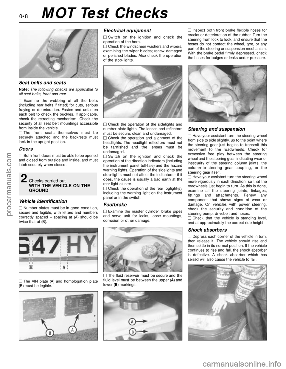
Seat belts and seats
Note: The following checks are applicable to
all seat belts, front and rear.
MExamine the webbing of all the belts
(including rear belts if fitted) for cuts, serious
fraying or deterioration. Fasten and unfasten
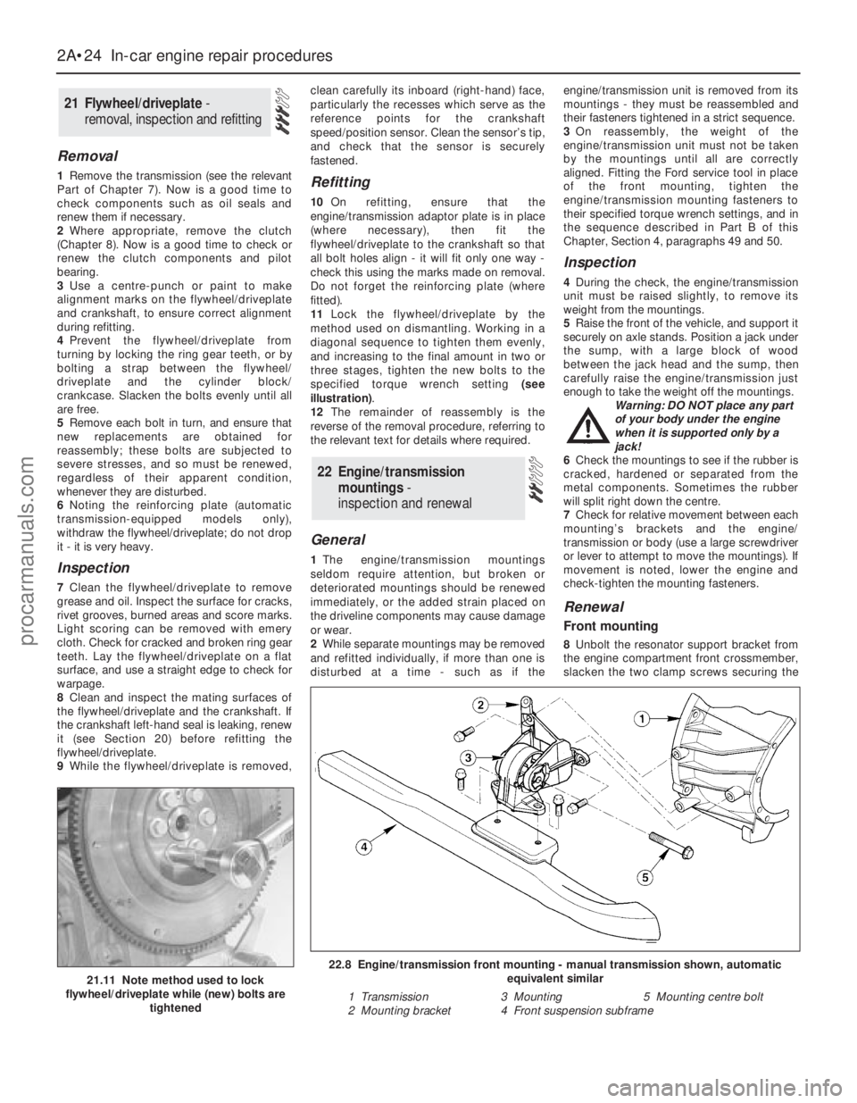
each belt to check the buckles. If applicable,
check the retracting mechanism. Check the
security of all seat belt mountings accessible
from inside the vehicle.
MThe front seats themselves must be
securely attached and the backrests must
lock in the upright position.
Doors
MBoth front doors must be able to be opened
and closed from outside and inside, and must
latch securely when closed.
Vehicle identification
MNumber plates must be in good condition,
secure and legible, with letters and numbers
correctly spaced – spacing at (A) should be
twice that at (B).
MThe VIN plate (A) and homologation plate
(B) must be legible.
Electrical equipment
MSwitch on the ignition and check the
operation of the horn.
MCheck the windscreen washers and wipers,
examining the wiper blades; renew damaged
or perished blades. Also check the operation
of the stop-lights.
MCheck the operation of the sidelights and
number plate lights. The lenses and reflectors
must be secure, clean and undamaged.
MCheck the operation and alignment of the
headlights. The headlight reflectors must not
be tarnished and the lenses must be
undamaged.
MSwitch on the ignition and check the
operation of the direction indicators (including
the instrument panel tell-tale) and the hazard
warning lights. Operation of the sidelights and
stop-lights must not affect the indicators - if it
does, the cause is usually a bad earth at the
rear light cluster.
MCheck the operation of the rear foglight(s),
including the warning light on the instrument
panel or in the switch.
Footbrake
MExamine the master cylinder, brake pipes
and servo unit for leaks, loose mountings,
corrosion or other damage.
MThe fluid reservoir must be secure and the
fluid level must be between the upper (A) and
lower (B) markings.MInspect both front brake flexible hoses for
cracks or deterioration of the rubber. Turn the
steering from lock to lock, and ensure that the
hoses do not contact the wheel, tyre, or any
part of the steering or suspension mechanism.
With the brake pedal firmly depressed, check
the hoses for bulges or leaks under pressure.
Steering and suspension
MHave your assistant turn the steering wheel
from side to side slightly, up to the point where
the steering gear just begins to transmit this
movement to the roadwheels. Check for
excessive free play between the steering
wheel and the steering gear, indicating wear or
insecurity of the steering column joints, the
column-to-steering gear coupling, or the
steering gear itself.
MHave your assistant turn the steering wheel
more vigorously in each direction, so that the
roadwheels just begin to turn. As this is done,
examine all the steering joints, linkages,
fittings and attachments. Renew any
component that shows signs of wear or
damage. On vehicles with power steering,
check the security and condition of the
steering pump, drivebelt and hoses.
MCheck that the vehicle is standing level,
and at approximately the correct ride height.
Shock absorbers
MDepress each corner of the vehicle in turn,
then release it. The vehicle should rise and
then settle in its normal position. If the vehicle
continues to rise and fall, the shock absorber
is defective. A shock absorber which has
seized will also cause the vehicle to fail.
2Checks carried out
WITH THE VEHICLE ON THE
GROUND
0•8MOT Test Checks
procarmanuals.com
Page 10 of 279
0•10
MExamine the handbrake mechanism,
checking for frayed or broken cables,
excessive corrosion, or wear or insecurity of
the linkage. Check that the mechanism works
on each relevant wheel, and releases fully,
without binding.
MIt is not possible to test brake efficiency
without special equipment, but a road test
can be carried out later to check that the
vehicle pulls up in a straight line.
Fuel and exhaust systems
MInspect the fuel tank (including the filler
cap), fuel pipes, hoses and unions. All
components must be secure and free from
leaks.
MExamine the exhaust system over its entire
length, checking for any damaged, broken or
missing mountings, security of the retaining
clamps and rust or corrosion.
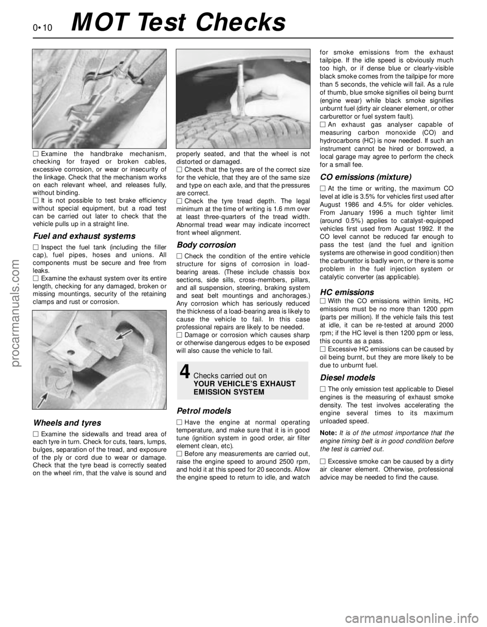
Wheels and tyres
MExamine the sidewalls and tread area of
each tyre in turn. Check for cuts, tears, lumps,
bulges, separation of the tread, and exposure
of the ply or cord due to wear or damage.
Check that the tyre bead is correctly seated
on the wheel rim, that the valve is sound andproperly seated, and that the wheel is not
distorted or damaged.
MCheck that the tyres are of the correct size
for the vehicle, that they are of the same size
and type on each axle, and that the pressures
are correct.
MCheck the tyre tread depth. The legal
minimum at the time of writing is 1.6 mm over
at least three-quarters of the tread width.
Abnormal tread wear may indicate incorrect
front wheel alignment.
Body corrosion
MCheck the condition of the entire vehicle
structure for signs of corrosion in load-
bearing areas. (These include chassis box
sections, side sills, cross-members, pillars,
and all suspension, steering, braking system
and seat belt mountings and anchorages.)
Any corrosion which has seriously reduced
the thickness of a load-bearing area is likely to
cause the vehicle to fail. In this case
professional repairs are likely to be needed.
MDamage or corrosion which causes sharp
or otherwise dangerous edges to be exposed
will also cause the vehicle to fail.
Petrol models
MHave the engine at normal operating
temperature, and make sure that it is in good
tune (ignition system in good order, air filter
element clean, etc).
MBefore any measurements are carried out,
raise the engine speed to around 2500 rpm,
and hold it at this speed for 20 seconds. Allow
the engine speed to return to idle, and watchfor smoke emissions from the exhaust
tailpipe. If the idle speed is obviously much
too high, or if dense blue or clearly-visible
black smoke comes from the tailpipe for more
than 5 seconds, the vehicle will fail. As a rule
of thumb, blue smoke signifies oil being burnt
(engine wear) while black smoke signifies
unburnt fuel (dirty air cleaner element, or other
carburettor or fuel system fault).
MAn exhaust gas analyser capable of
measuring carbon monoxide (CO) and
hydrocarbons (HC) is now needed. If such an
instrument cannot be hired or borrowed, a
local garage may agree to perform the check
for a small fee.
CO emissions (mixture)
MAt the time or writing, the maximum CO
level at idle is 3.5% for vehicles first used after
August 1986 and 4.5% for older vehicles.
From January 1996 a much tighter limit
(around 0.5%) applies to catalyst-equipped
vehicles first used from August 1992. If the
CO level cannot be reduced far enough to
pass the test (and the fuel and ignition
systems are otherwise in good condition) then
the carburettor is badly worn, or there is some
problem in the fuel injection system or
catalytic converter (as applicable).
HC emissionsMWith the CO emissions within limits, HC
emissions must be no more than 1200 ppm
(parts per million). If the vehicle fails this test
at idle, it can be re-tested at around 2000
rpm; if the HC level is then 1200 ppm or less,
this counts as a pass.
MExcessive HC emissions can be caused by
oil being burnt, but they are more likely to be
due to unburnt fuel.
Diesel models
MThe only emission test applicable to Diesel
engines is the measuring of exhaust smoke
density. The test involves accelerating the
engine several times to its maximum
unloaded speed.
Note: It is of the utmost importance that the
engine timing belt is in good condition before
the test is carried out.
M
Excessive smoke can be caused by a dirty
air cleaner element. Otherwise, professional
advice may be needed to find the cause.
4Checks carried out on
YOUR VEHICLE’S EXHAUST
EMISSION SYSTEM
MOT Test Checks
procarmanuals.com
Page 23 of 279
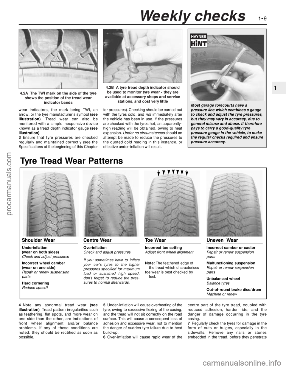
wear indicators, the mark being TWI, an
arrow, or the tyre manufacturer’s symbol (see
illustration). Tread wear can also be
monitored with a simple inexpensive device
known as a tread depth indicator gauge (see
illustration).
3Ensure that tyre pressures are checked
regularly and maintained correctly (see the
Specifications at the beginning of this Chapterfor pressures). Checking should be carried out
with the tyres cold, and notimmediately after
the vehicle has been in use. If the pressures
are checked with the tyres hot, an apparently-
high reading will be obtained, owing to heat
expansion. Under no circumstancesshould an
attempt be made to reduce the pressures to
the quoted cold reading in this instance, or
effective under-inflation will result.
1•9
1
Tyre Tread Wear Patterns
Shoulder Wear
Underinflation
(wear on both sides)
Check and adjust pressures
Incorrect wheel camber
(wear on one side)
Repair or renew suspension
parts
Hard cornering
Reduce speed!
Centre Wear
Overinflation
Check and adjust pressures
If you sometimes have to inflate
your car’s tyres to the higher
pressures specified for maximum
load or sustained high speed,
don’t forget to reduce the pres-
sures to normal afterwards.
Toe Wear
Incorrect toe setting
Adjust front wheel alignment
Note: The feathered edge of
the tread which characterises
toe wear is best checked by
feel.
Uneven Wear
Incorrect camber or castor
Repair or renew suspension
parts
Malfunctioning suspension
Repair or renew suspension
parts
Unbalanced wheel
Balance tyres
Out-of-round brake disc/drum
Machine or renew
4.2A The TWI mark on the side of the tyre
shows the position of the tread wear
indicator bands
4.2B A tyre tread depth indicator should
be used to monitor tyre wear - they are
available at accessory shops and service
stations, and cost very little
Weekly checks
Most garage forecourts have a
pressure line which combines a gauge
to check and adjust the tyre pressures,
but they may vary in accuracy, due to
general misuse and abuse. It therefore
pays to carry a good-quality tyre
pressure gauge in the vehicle, to make
the regular checks required and ensure
pressure accuracy.
4Note any abnormal tread wear (see
illustration). Tread pattern irregularities such
as feathering, flat spots, and more wear on
one side than the other, are indications of
front wheel alignment and/or balance
problems. If any of these conditions are
noted, they should be rectified as soon as
possible.5Under-inflation will cause overheating of the
tyre, owing to excessive flexing of the casing,
and the tread will not sit correctly on the road
surface. This will cause a consequent loss of
adhesion and excessive wear, not to mention
the danger of sudden tyre failure due to heat
build-up.
6Over-inflation will cause rapid wear of thecentre part of the tyre tread, coupled with
reduced adhesion, harder ride, and the
danger of damage occurring in the tyre
casing.
7Regularly check the tyres for damage in the
form of cuts or bulges, especially in the
sidewalls. Remove any nails or stones
embedded in the tread, before they penetrate
procarmanuals.com
Page 24 of 279
the tyre to cause deflation. If removal of a nail
reveals that the tyre has been punctured, refit
the nail, so that its point of penetration is
marked. Then immediately change the wheel,
and have the tyre repaired by a tyre dealer. Do
not drive on a tyre in such a condition. If in any
doubt as to the possible consequences of any
damage found, consult your local tyre dealer
for advice.
8General tyre wear is influenced to a large
degree by driving style - harsh braking and
acceleration, or fast cornering, will all produce
more rapid tyre wear. Interchanging of tyres
may result in more even wear; however, it is
worth bearing in mind that if this is completely
effective, the added expense is incurred of
replacing simultaneously a complete set of
tyres, which may prove financially restrictive
for many owners.
9Front tyres may wear unevenly as a result of
wheel misalignment. The front wheels should
always be correctly aligned according to the
settings specified by the vehicle
manufacturer.10Don’t forget to check the spare tyre for
condition and pressure.
11Legal restrictions apply to many aspects
of tyre fitting and usage, and in the UK this
information is contained in the Motor Vehicle
Construction and Use Regulations. It is
suggested that a copy of these regulations is
obtained from your local police, if in doubt as
to current legal requirements with regard to
tyre type and condition, minimum tread depth,
etc.
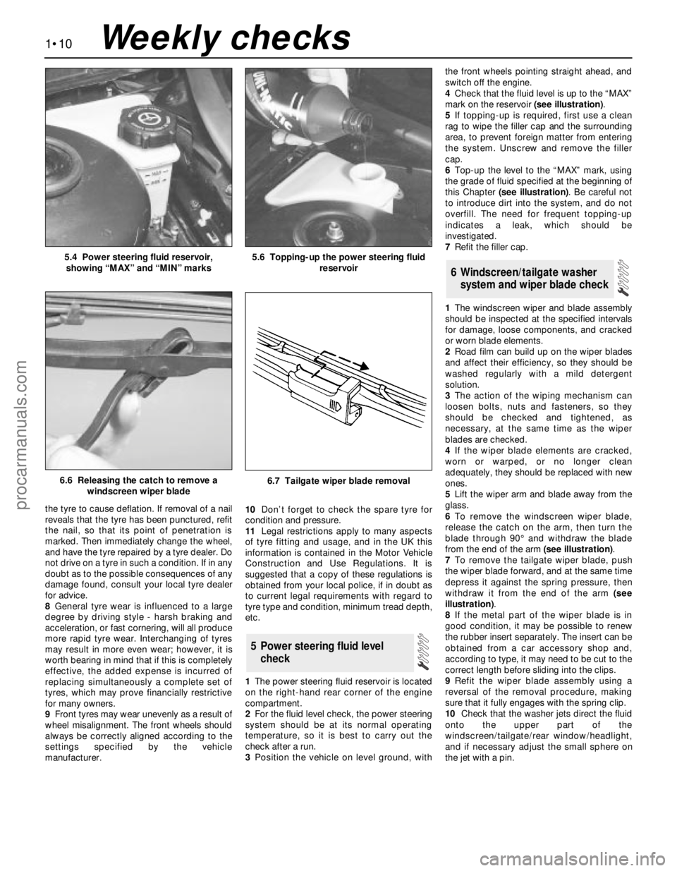
1The power steering fluid reservoir is located
on the right-hand rear corner of the engine
compartment.
2For the fluid level check, the power steering
system should be at its normal operating
temperature, so it is best to carry out the
check after a run.
3Position the vehicle on level ground, withthe front wheels pointing straight ahead, and
switch off the engine.
4Check that the fluid level is up to the “MAX”
mark on the reservoir (see illustration).
5If topping-up is required, first use a clean
rag to wipe the filler cap and the surrounding
area, to prevent foreign matter from entering
the system. Unscrew and remove the filler
cap.
6Top-up the level to the “MAX” mark, using
the grade of fluid specified at the beginning of
this Chapter (see illustration). Be careful not
to introduce dirt into the system, and do not
overfill. The need for frequent topping-up
indicates a leak, which should be
investigated.
7Refit the filler cap.
1The windscreen wiper and blade assembly
should be inspected at the specified intervals
for damage, loose components, and cracked
or worn blade elements.
2Road film can build up on the wiper blades
and affect their efficiency, so they should be
washed regularly with a mild detergent
solution.
3The action of the wiping mechanism can
loosen bolts, nuts and fasteners, so they
should be checked and tightened, as
necessary, at the same time as the wiper
blades are checked.
4If the wiper blade elements are cracked,
worn or warped, or no longer clean
adequately, they should be replaced with new
ones.
5Lift the wiper arm and blade away from the
glass.
6To remove the windscreen wiper blade,
release the catch on the arm, then turn the
blade through 90° and withdraw the blade
from the end of the arm (see illustration).
7To remove the tailgate wiper blade, push
the wiper blade forward, and at the same time
depress it against the spring pressure, then
withdraw it from the end of the arm (see
illustration).
8If the metal part of the wiper blade is in
good condition, it may be possible to renew
the rubber insert separately. The insert can be
obtained from a car accessory shop and,
according to type, it may need to be cut to the
correct length before sliding into the clips.
9Refit the wiper blade assembly using a
reversal of the removal procedure, making
sure that it fully engages with the spring clip.
10Check that the washer jets direct the fluid
onto the upper part of the
windscreen/tailgate/rear window/headlight,
and if necessary adjust the small sphere on
the jet with a pin.
6 Windscreen/tailgate washer
system and wiper blade check
5 Power steering fluid level
check
1•10
5.4 Power steering fluid reservoir,
showing “MAX” and “MIN” marks5.6 Topping-up the power steering fluid
reservoir
6.7 Tailgate wiper blade removal6.6 Releasing the catch to remove a
windscreen wiper blade
Weekly checks
procarmanuals.com
Page 64 of 279
Removal
1Remove the transmission (see the relevant
Part of Chapter 7). Now is a good time to
check components such as oil seals and
renew them if necessary.
2Where appropriate, remove the clutch
(Chapter 8). Now is a good time to check or
renew the clutch components and pilot
bearing.
3Use a centre-punch or paint to make
alignment marks on the flywheel/driveplate
and crankshaft, to ensure correct alignment
during refitting.
4Prevent the flywheel/driveplate from
turning by locking the ring gear teeth, or by
bolting a strap between the flywheel/
driveplate and the cylinder block/
crankcase. Slacken the bolts evenly until all
are free.
5Remove each bolt in turn, and ensure that
new replacements are obtained for
reassembly; these bolts are subjected to
severe stresses, and so must be renewed,
regardless of their apparent condition,
whenever they are disturbed.
6Noting the reinforcing plate (automatic
transmission-equipped models only),
withdraw the flywheel/driveplate; do not drop
it - it is very heavy.
Inspection
7Clean the flywheel/driveplate to remove
grease and oil. Inspect the surface for cracks,
rivet grooves, burned areas and score marks.
Light scoring can be removed with emery
cloth. Check for cracked and broken ring gear
teeth. Lay the flywheel/driveplate on a flat
surface, and use a straight edge to check for
warpage.
8Clean and inspect the mating surfaces of
the flywheel/driveplate and the crankshaft. If
the crankshaft left-hand seal is leaking, renew
it (see Section 20) before refitting the
flywheel/driveplate.
9While the flywheel/driveplate is removed,clean carefully its inboard (right-hand) face,
particularly the recesses which serve as the
reference points for the crankshaft
speed/position sensor. Clean the sensor’s tip,
and check that the sensor is securely
fastened.
Refitting
10On refitting, ensure that the
engine/transmission adaptor plate is in place
(where necessary), then fit the
flywheel/driveplate to the crankshaft so that
all bolt holes align - it will fit only one way -
check this using the marks made on removal.
Do not forget the reinforcing plate (where
fitted).
11Lock the flywheel/driveplate by the
method used on dismantling. Working in a
diagonal sequence to tighten them evenly,
and increasing to the final amount in two or
three stages, tighten the new bolts to the
specified torque wrench setting (see
illustration).
12The remainder of reassembly is the
reverse of the removal procedure, referring to
the relevant text for details where required.
General
1The engine/transmission mountings
seldom require attention, but broken or
deteriorated mountings should be renewed
immediately, or the added strain placed on
the driveline components may cause damage
or wear.
2While separate mountings may be removed
and refitted individually, if more than one is
disturbed at a time - such as if theengine/transmission unit is removed from its
mountings - they must be reassembled and
their fasteners tightened in a strict sequence.
3On reassembly, the weight of the
engine/transmission unit must not be taken
by the mountings until all are correctly
aligned. Fitting the Ford service tool in place
of the front mounting, tighten the
engine/transmission mounting fasteners to
their specified torque wrench settings, and in
the sequence described in Part B of this
Chapter, Section 4, paragraphs 49 and 50.
Inspection
4During the check, the engine/transmission
unit must be raised slightly, to remove its
weight from the mountings.
5Raise the front of the vehicle, and support it
securely on axle stands. Position a jack under
the sump, with a large block of wood
between the jack head and the sump, then
carefully raise the engine/transmission just
enough to take the weight off the mountings.
Warning: DO NOT place any part
of your body under the engine
when it is supported only by a
jack!
6Check the mountings to see if the rubber is
cracked, hardened or separated from the
metal components. Sometimes the rubber
will split right down the centre.
7Check for relative movement between each
mounting’s brackets and the engine/
transmission or body (use a large screwdriver
or lever to attempt to move the mountings). If
movement is noted, lower the engine and
check-tighten the mounting fasteners.
Renewal
Front mounting
8Unbolt the resonator support bracket from
the engine compartment front crossmember,
slacken the two clamp screws securing the
22 Engine/transmission
mountings -
inspection and renewal
21 Flywheel/driveplate -
removal, inspection and refitting
2A•24 In-car engine repair procedures
21.11 Note method used to lock
flywheel/driveplate while (new) bolts are
tightened
22.8 Engine/transmission front mounting - manual transmission shown, automatic
equivalent similar
1 Transmission 3 Mounting 5 Mounting centre bolt
2 Mounting bracket 4 Front suspension subframe
procarmanuals.com
Page 75 of 279
gear linkage heat shield. Reconnect the
gearchange linkage and transmission support
rods to the transmission, adjusting the linkage
using the marks made on removal (see
Chapter 7, Part A, for details).
56Re-install the remaining components and
fasteners in the reverse order of removal.
57Add coolant, engine oil and transmission
fluids as needed (see Chapter 1).
58Run the engine, and check for proper
operation and the absence of leaks. Shut off
the engine, and recheck the fluid levels.
59Remember that, since the front suspension
subframe and steering gear have been
disturbed, the wheel alignment and steering
angles must be checked fully and carefully as
soon as possible, with any necessary
adjustments being made. This operation is best
carried out by an experienced mechanic, using
proper checking equipment; the vehicle should
therefore be taken to a Ford dealer or similarly-
qualified person for attention.
1It is much easier to dismantle and work on
the engine if it is mounted on a portable engine
stand. These stands can often be hired from a
tool hire shop. Before the engine is mounted
on a stand, the flywheel/driveplate should be
removed (Part A of this Chapter, Section 21)
so that the stand bolts can be tightened into
the end of the cylinder block/crankcase.
2If a stand is not available, it is possible to
dismantle the engine with it mounted on
blocks, on a sturdy workbench or on the floor.
Be extra-careful not to tip or drop the engine
when working without a stand.
3If you are going to obtain a reconditioned
engine, all external components must be
removed first, to be transferred to the
replacement engine (just as they will if you are
doing a complete engine overhaul yourself).
Note:When removing the external
components from the engine, pay close
attention to details that may be helpful or
important during refitting. Note the fitted
position of gaskets, seals, spacers, pins,
washers, bolts and other small items.These
external components include the following:
(a) Alternator and brackets (Chapter 5).
(b) HT leads and spark plugs (Chapter 1).
(c) Thermostat and housing (Chapter 3).
(d) Dipstick tube.
(e) Fuel injection system components
(Chapter 4).
(f) All electrical switches and sensors - refer
to the appropriate Chapter.
(g) Inlet and exhaust manifolds (Part A of this
Chapter).
(h) Oil filter (Chapter 1).
(i) Engine/transmission mounting brackets
(Part A of this Chapter, Section 22).
(j) Flywheel/driveplate (Part A of this
Chapter, Section 21).
4If you are obtaining a “short” engine (whichconsists of the engine cylinder
block/crankcase, crankshaft, pistons and
connecting rods all assembled), then the
cylinder head, sump, oil pump, and timing belt
will have to be removed also.
5If you are planning a complete overhaul, the
engine can be dismantled and the internal
components removed in the following order.
(a) Inlet and exhaust manifolds (Part A of this
Chapter).
(b) Timing belt, toothed pulleys and
tensioner, and timing belt inner cover
(Part A of this Chapter).
(c) Cylinder head (Part A of this Chapter,
Section 14).
(d) Flywheel/driveplate (Part A of this
Chapter, Section 21).
(e) Sump (Part A of this Chapter, Section 15).
(f) Oil pump (Part A of this Chapter, Sec-
tion 16).
(g) Piston/connecting rod assemblies
(Section 9).
(h) Crankshaft (Section 10).
6Before beginning the dismantling andoverhaul procedures, make sure that you have
all of the correct tools necessary. Refer to the
introductory pages at the beginning of this
manual for further information.
Note:New and reconditioned cylinder heads
are available from the manufacturers, and
from engine overhaul specialists. Due to the
fact that some specialist tools are required for
the dismantling and inspection procedures,
and new components may not be readily
available (refer to Section 1 of this Part), it may
be more practical and economical for the
home mechanic to purchase a reconditioned
head, rather than to dismantle, inspect and
recondition the original head.
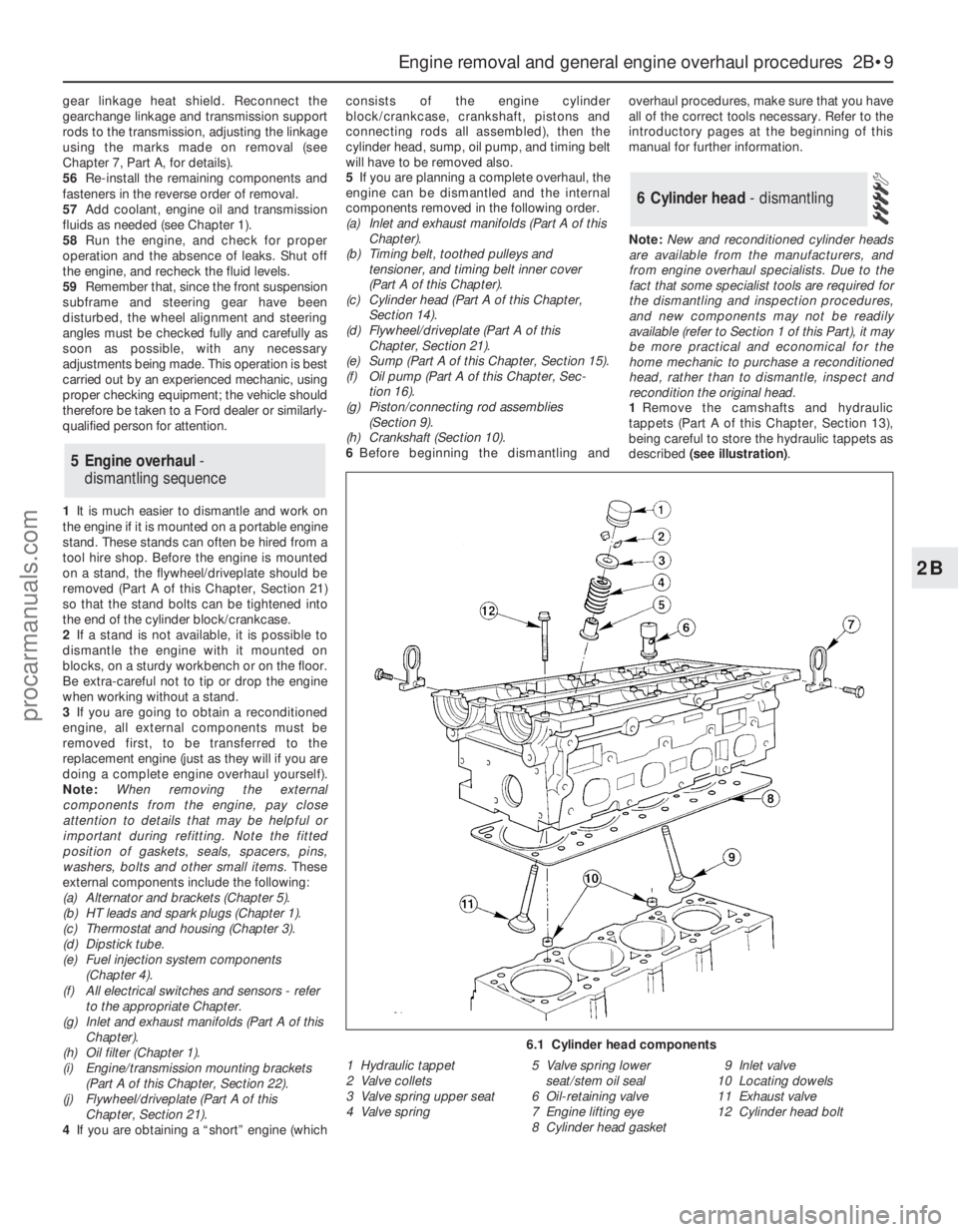
1Remove the camshafts and hydraulic
tappets (Part A of this Chapter, Section 13),
being careful to store the hydraulic tappets as
described (see illustration).
6 Cylinder head - dismantling
5 Engine overhaul-
dismantling sequence
Engine removal and general engine overhaul procedures 2B•9
2B
6.1 Cylinder head components
1 Hydraulic tappet
2 Valve collets
3 Valve spring upper seat
4 Valve spring5 Valve spring lower
seat/stem oil seal
6 Oil-retaining valve
7 Engine lifting eye
8 Cylinder head gasket9 Inlet valve
10 Locating dowels
11 Exhaust valve
12 Cylinder head bolt
procarmanuals.com
Page 149 of 279
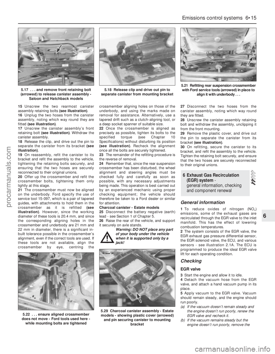
15Unscrew the two rearmost canister
assembly retaining bolts (see illustration).
16Unplug the two hoses from the canister
assembly, noting which way round they are
fitted (see illustration).
17Unscrew the canister assembly’s front
retaining bolt (see illustration). Withdraw the
canister assembly.
18Release the clip, and drive out the pin to
separate the canister from its bracket (see
illustration).
19On reassembly, refit the canister to its
bracket and refit the assembly to the vehicle,
tightening the retaining bolts securely, and
ensuring that the two hoses are securely
reconnected to their original unions.
20Offer up the crossmember and refit the
crossmember bolts, tightening them only
lightly at this stage.
21The crossmember must now be aligned
on the underbody. Ford specify the use of
service tool 15-097, which is a pair of tapered
guides, with attachments to hold them in the
crossmember as it is refitted (see
illustration). However, since the working
diameter of these tools is 20.4 mm, and since
the corresponding aligning holes in the
crossmember and underbody are 21 mm and
22 mm in diameter, there is a significant in-
built tolerance possible in the crossmember’s
alignment, even if the correct tools are used. If
these tools are not available, align the
crossmember by eye, centring thecrossmember aligning holes on those of the
underbody, and using the marks made on
removal for assistance. Alternatively, use a
tapered drift such as a clutch-aligning tool, or
a deep socket spanner of suitable size.
22Once the crossmember is aligned as
precisely as possible, tighten its bolts to the
specified torque (see Chapter 10
Specifications) without disturbing its position
(see illustration). Recheck the alignment
once all the bolts are securely tightened.
23The remainder of the refitting procedure is
the reverse of removal.
24Remember that, since the rear suspension
crossmember has been disturbed, the wheel
alignment and steering angles must be
checked fully and carefully as soon as
possible, with any necessary adjustments
being made. This operation is best carried out
by an experienced mechanic using proper
checking equipment; the vehicle should
therefore be taken to a Ford dealer or similar
for attention.
Charcoal canister - Estate models
25Disconnect the battery negative (earth)
lead - see Section 1 of Chapter 5.
26Raise the rear of the vehicle, and support
it securely on axle stands.
Warning: DO NOT place any part
of your body under the vehicle
when it is supported only by a
jack!27Disconnect the two hoses from the
canister assembly, noting which way round
they are fitted.
28Unscrew the canister assembly retaining
bolt and withdraw the assembly, unclipping it
from the front mounting.
29Remove the plastic cover, and drive out
the pin to separate the canister from its
bracket (see illustration).
30On refitting, secure the canister to its
bracket, and refit the assembly to the vehicle.
Tighten the retaining bolt securely, and ensure
that the two hoses are securely reconnected
to their original unions.
General information
1To reduce oxides of nitrogen (NOx)
emissions, some of the exhaust gases are
recirculated through the EGR valve to the inlet
manifold. This has the effect of lowering
combustion temperatures.
2The system consists of the EGR valve, the
EGR exhaust gas pressure differential sensor,
the EGR solenoid valve, the ECU, and various
sensors - see illustration 2.1A. The ECU is
programmed to produce the ideal EGR valve
lift for each operating condition.
Checking
EGR valve
3Start the engine and allow it to idle.
4Detach the vacuum hose from the EGR
valve, and attach a hand vacuum pump in its
place.
5Apply vacuum to the EGR valve. Vacuum
should remain steady, and the engine should
run poorly.
(a) If the vacuum doesn’t remain steady and
the engine doesn’t run poorly, renew the
EGR valve and recheck it.
(b) If the vacuum remains steady but the
engine doesn’t run poorly, remove the
6 Exhaust Gas Recirculation
(EGR) system-
general information, checking
and component renewal
Emissions control systems 6•15
6
5.22 . . . ensure aligned crossmember
does not move - Ford tools used here -
while mounting bolts are tightened5.29 Charcoal canister assembly - Estate
models - showing plastic cover (arrowed)
and pin securing canister to mounting
bracket
5.17 . . . and remove front retaining bolt
(arrowed) to release canister assembly -
Saloon and Hatchback models5.18 Release clip and drive out pin to
separate canister from mounting bracket5.21 Refitting rear suspension crossmember
with Ford service tools (arrowed) in place to
align it with underbody . . .
procarmanuals.com
Page 155 of 279
Chapter 10 Suspension and steering systems
Front anti-roll bar and links - removal and refitting . . . . . . . . . . . . . . 6
Front hub and bearings - inspection and renewal . . . . . . . . . . . . . . 3
Front suspension lower arm - removal, overhaul and refitting . . . . . 7
Front suspension lower arm balljoint - renewal . . . . . . . . . . . . . . . . 8
Front suspension strut - overhaul . . . . . . . . . . . . . . . . . . . . . . . . . . . 5
Front suspension strut - removal and refitting . . . . . . . . . . . . . . . . . 4
General information . . . . . . . . . . . . . . . . . . . . . . . . . . . . . . . . . . . . . . 1
Power steering fluid level check . . . . . . . . . . . . . . . . . See Chapter 1
Power steering gear (all except left-hand-drive models
with ABS) - removal and refitting . . . . . . . . . . . . . . . . . . . . . . . . . . 30
Power steering gear (left-hand-drive models with ABS) -
removal and refitting . . . . . . . . . . . . . . . . . . . . . . . . . . . . . . . . . . . 31
Power steering gear rubber gaiters - renewal . . . . . . . . . . . . . . . . . . 32
Power steering hydraulic system - bleeding . . . . . . . . . . . . . . . . . . . 33
Power steering pump - removal and refitting . . . . . . . . . . . . . . . . . . 34
Rear anti-roll bar and links (Estate models) - removal and refitting . 20
Rear anti-roll bar and links (Saloon/Hatchback models) -
removal and refitting . . . . . . . . . . . . . . . . . . . . . . . . . . . . . . . . . . . 13
Rear coil spring (Estate models) - removal and refitting . . . . . . . . . . 21
Rear hub and bearings (Estate models) - inspection and renewal . . 17
Rear hub and bearings (Saloon/Hatchback models) -
inspection and renewal . . . . . . . . . . . . . . . . . . . . . . . . . . . . . . . . . 9
Rear shock absorber (Estate models) - removal, testing and refitting . 19
Rear suspension crossmember (Estate models) - removal
and refitting . . . . . . . . . . . . . . . . . . . . . . . . . . . . . . . . . . . . . . . . . . 26
Rear suspension crossmember (Saloon/Hatchback models) -
removal and refitting . . . . . . . . . . . . . . . . . . . . . . . . . . . . . . . . . . . 16Rear suspension front lower arm (Estate models) - removal
and refitting . . . . . . . . . . . . . . . . . . . . . . . . . . . . . . . . . . . . . . . . . . 23
Rear suspension knuckle (Estate models) - removal and refitting . . 18
Rear suspension knuckle (Saloon/Hatchback models) - removal
and refitting . . . . . . . . . . . . . . . . . . . . . . . . . . . . . . . . . . . . . . . . . . 10
Rear suspension lower arms (Saloon/Hatchback models) -
removal and refitting . . . . . . . . . . . . . . . . . . . . . . . . . . . . . . . . . . . 14
Rear suspension rear lower arm (Estate models) - removal
and refitting . . . . . . . . . . . . . . . . . . . . . . . . . . . . . . . . . . . . . . . . . . 22
Rear suspension strut (Saloon/Hatchback models) - overhaul . . . . . 12
Rear suspension strut (Saloon/Hatchback models) -
removal and refitting . . . . . . . . . . . . . . . . . . . . . . . . . . . . . . . . . . . 11
Rear suspension tie-bar (Estate models) - removal and refitting . . . 25
Rear suspension tie-bar (Saloon/Hatchback models) -
removal and refitting . . . . . . . . . . . . . . . . . . . . . . . . . . . . . . . . . . . 15
Rear suspension upper arm (Estate models) - removal
and refitting . . . . . . . . . . . . . . . . . . . . . . . . . . . . . . . . . . . . . . . . . . 24
Steering column - removal, inspection and refitting . . . . . . . . . . . . . 28
Steering column flexible coupling - removal and refitting . . . . . . . . . 29
Steering knuckle and hub assembly - removal and refitting . . . . . . . 2
Steering, suspension and wheel check . . . . . . . . . . . . See Chapter 1
Steering wheel - removal and refitting . . . . . . . . . . . . . . . . . . . . . . . 27
Track rod end - renewal . . . . . . . . . . . . . . . . . . . . . . . . . . . . . . . . . . 35
Tyre condition and tyre pressure checks . . . . . . . . . . . See Chapter 1
Wheel alignment and steering angles - general information . . . . . . . 36
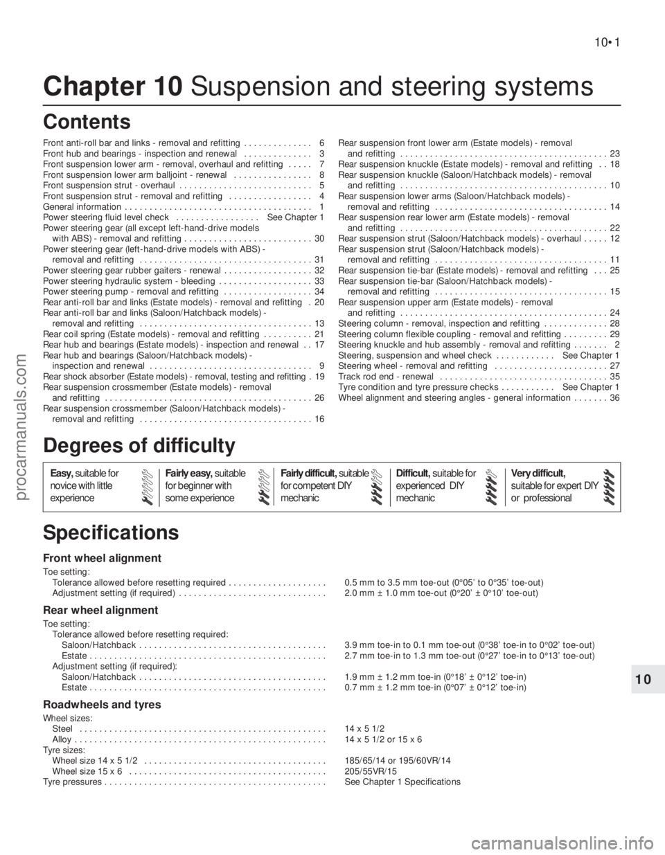
Front wheel alignment
Toe setting:
Tolerance allowed before resetting required . . . . . . . . . . . . . . . . . . . . 0.5 mm to 3.5 mm toe-out (0°05’ to 0°35’ toe-out)
Adjustment setting (if required) . . . . . . . . . . . . . . . . . . . . . . . . . . . . . . 2.0 mm ± 1.0 mm toe-out (0°20’ ± 0°10’ toe-out)
Rear wheel alignment
Toe setting:
Tolerance allowed before resetting required:
Saloon/Hatchback . . . . . . . . . . . . . . . . . . . . . . . . . . . . . . . . . . . . . . 3.9 mm toe-in to 0.1 mm toe-out (0°38’ toe-in to 0°02’ toe-out)
Estate . . . . . . . . . . . . . . . . . . . . . . . . . . . . . . . . . . . . . . . . . . . . . . . . 2.7 mm toe-in to 1.3 mm toe-out (0°27’ toe-in to 0°13’ toe-out)
Adjustment setting (if required):
Saloon/Hatchback . . . . . . . . . . . . . . . . . . . . . . . . . . . . . . . . . . . . . . 1.9 mm ± 1.2 mm toe-in (0°18’ ± 0°12’ toe-in)
Estate . . . . . . . . . . . . . . . . . . . . . . . . . . . . . . . . . . . . . . . . . . . . . . . . 0.7 mm ± 1.2 mm toe-in (0°07’ ± 0°12’ toe-in)
Roadwheels and tyres
Wheel sizes:
Steel . . . . . . . . . . . . . . . . . . . . . . . . . . . . . . . . . . . . . . . . . . . . . . . . . . 14 x 5 1/2
Alloy . . . . . . . . . . . . . . . . . . . . . . . . . . . . . . . . . . . . . . . . . . . . . . . . . . . 14 x 5 1/2 or 15 x 6
Tyre sizes:
Wheel size 14 x 5 1/2 . . . . . . . . . . . . . . . . . . . . . . . . . . . . . . . . . . . . . 185/65/14 or 195/60VR/14
Wheel size 15 x 6 . . . . . . . . . . . . . . . . . . . . . . . . . . . . . . . . . . . . . . . . 205/55VR/15
Tyre pressures . . . . . . . . . . . . . . . . . . . . . . . . . . . . . . . . . . . . . . . . . . . . . See Chapter 1 Specifications
10•1
Easy,suitable for
novice with little
experienceFairly easy,suitable
for beginner with
some experienceFairly difficult,suitable
for competent DIY
mechanicDifficult,suitable for
experienced DIY
mechanicVery difficult,
suitable for expert DIY
or professional
Degrees of difficulty
Specifications Contents
10
procarmanuals.com