1993 FORD MONDEO wheel alignment
[x] Cancel search: wheel alignmentPage 177 of 279
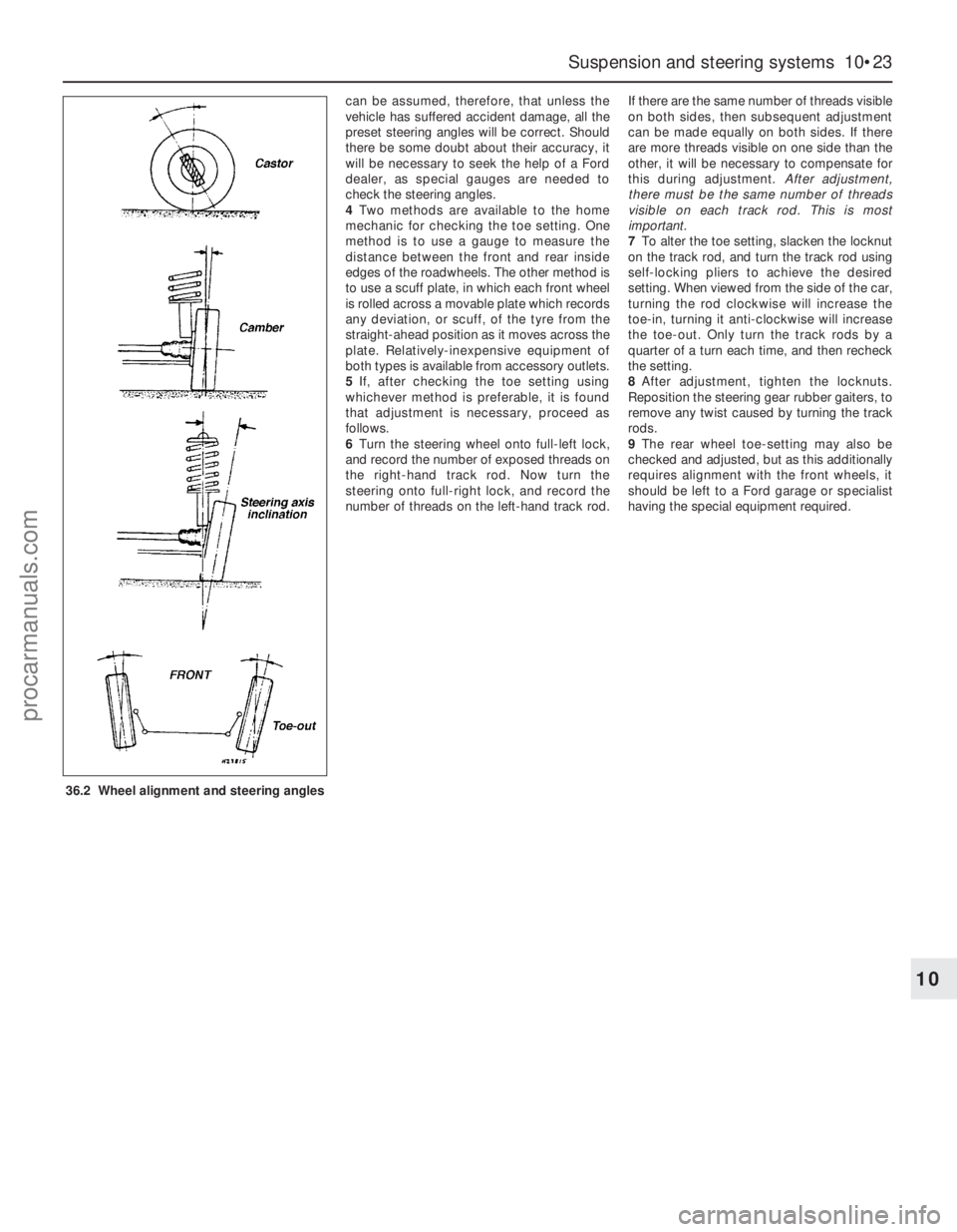
can be assumed, therefore, that unless the
vehicle has suffered accident damage, all the
preset steering angles will be correct. Should
there be some doubt about their accuracy, it
will be necessary to seek the help of a Ford
dealer, as special gauges are needed to
check the steering angles.
4Two methods are available to the home
mechanic for checking the toe setting. One
method is to use a gauge to measure the
distance between the front and rear inside
edges of the roadwheels. The other method is
to use a scuff plate, in which each front wheel
is rolled across a movable plate which records
any deviation, or scuff, of the tyre from the
straight-ahead position as it moves across the
plate. Relatively-inexpensive equipment of
both types is available from accessory outlets.
5If, after checking the toe setting using
whichever method is preferable, it is found
that adjustment is necessary, proceed as
follows.
6Turn the steering wheel onto full-left lock,
and record the number of exposed threads on
the right-hand track rod. Now turn the
steering onto full-right lock, and record the
number of threads on the left-hand track rod.If there are the same number of threads visible
on both sides, then subsequent adjustment
can be made equally on both sides. If there
are more threads visible on one side than the
other, it will be necessary to compensate for
this during adjustment. After adjustment,
there must be the same number of threads
visible on each track rod. This is most
important.
7To alter the toe setting, slacken the locknut
on the track rod, and turn the track rod using
self-locking pliers to achieve the desired
setting. When viewed from the side of the car,
turning the rod clockwise will increase the
toe-in, turning it anti-clockwise will increase
the toe-out. Only turn the track rods by a
quarter of a turn each time, and then recheck
the setting.
8After adjustment, tighten the locknuts.
Reposition the steering gear rubber gaiters, to
remove any twist caused by turning the track
rods.
9The rear wheel toe-setting may also be
checked and adjusted, but as this additionally
requires alignment with the front wheels, it
should be left to a Ford garage or specialist
having the special equipment required.
Suspension and steering systems 10•23
10
36.2 Wheel alignment and steering angles
procarmanuals.com
Page 181 of 279
Mix up a little filler on a clean piece of card
or board - measure the hardener carefully
(follow the maker’s instructions on the pack),
otherwise the filler will set too rapidly or too
slowly. Using the applicator, apply the filler
paste to the prepared area; draw the
applicator across the surface of the filler to
achieve the correct contour and to level the
surface. As soon as a contour that
approximates to the correct one is achieved,
stop working the paste - if you carry on too
long, the paste will become sticky and begin
to “pick-up” on the applicator. Continue to
add thin layers of filler paste at 20-minute
intervals, until the level of the filler is just
proud of the surrounding bodywork.
Once the filler has hardened, the excess
can be removed using a metal plane or file.
From then on, progressively-finer grades of
abrasive paper should be used, starting with a
40-grade production paper, and finishing with
a 400-grade wet-and-dry paper. Always wrap
the abrasive paper around a flat rubber, cork,
or wooden block - otherwise the surface of
the filler will not be completely flat. During the
smoothing of the filler surface, the wet-and-
dry paper should be periodically rinsed in
water. This will ensure that a very smooth
finish is imparted to the filler at the final stage.
At this stage, the “dent” should be
surrounded by a ring of bare metal, which in
turn should be encircled by the finely
“feathered” edge of the good paintwork.
Rinse the repair area with clean water, until all
of the dust produced by the rubbing-down
operation has gone.
Spray the whole area with a light coat of
primer - this will show up any imperfections in
the surface of the filler. Repair these
imperfections with fresh filler paste or
bodystopper, and once more smooth the
surface with abrasive paper. Repeat this
spray-and-repair procedure until you are
satisfied that the surface of the filler, and the
feathered edge of the paintwork, are perfect.
Clean the repair area with clean water, and
allow to dry fully.
The repair area is now ready for final
spraying. Paint spraying must be carried out
in a warm, dry, windless and dust-free
atmosphere. This condition can be created
artificially if you have access to a large indoor
working area, but if you are forced to work in
the open, you will have to pick your day very
carefully. If you are working indoors, dousing
the floor in the work area with water will help
to settle the dust which would otherwise be in
the atmosphere. If the repair area is confined
to one body panel, mask off the surrounding
panels; this will help to minimise the effects ofa slight mis-match in paint colours. Bodywork
fittings (eg chrome strips, door handles etc)
will also need to be masked off. Use genuine
masking tape, and several thicknesses of
newspaper, for the masking operations.
Before commencing to spray, agitate the
aerosol can thoroughly, then spray a test area
(an old tin, or similar) until the technique is
mastered. Cover the repair area with a thick
coat of primer; the thickness should be built
up using several thin layers of paint, rather
than one thick one. Using 400-grade wet-and-
dry paper, rub down the surface of the primer
until it is really smooth. While doing this, the
work area should be thoroughly doused with
water, and the wet-and-dry paper periodically
rinsed in water. Allow to dry before spraying
on more paint.
Spray on the top coat, again building up the
thickness by using several thin layers of paint.
Start spraying at one edge of the repair area,
and then, using a side-to-side motion, work
until the whole repair area and about 2 inches
of the surrounding original paintwork is
covered. Remove all masking material 10 to
15 minutes after spraying on the final coat of
paint.
Allow the new paint at least two weeks to
harden, then, using a paintwork renovator, or
a very fine cutting paste, blend the edges of
the paint into the existing paintwork. Finally,
apply wax polish.
Plastic components
With the use of more and more plastic body
components by the vehicle manufacturers (eg
bumpers. spoilers, and in some cases major
body panels), rectification of more serious
damage to such items has become a matter
of either entrusting repair work to a specialist
in this field, or renewing complete
components. Repair of such damage by the
DIY owner is not really feasible, owing to the
cost of the equipment and materials required
for effecting such repairs. The basic technique
involves making a groove along the line of the
crack in the plastic, using a rotary burr in a
power drill. The damaged part is then welded
back together, using a hot-air gun to heat up
and fuse a plastic filler rod into the groove.
Any excess plastic is then removed, and the
area rubbed down to a smooth finish. It is
important that a filler rod of the correct plastic
is used, as body components can be made of
a variety of different types (eg polycarbonate,
ABS, polypropylene).
Damage of a less serious nature (abrasions,
minor cracks etc) can be repaired by the DIY
owner using a two-part epoxy filler repair
material. Once mixed in equal proportions,
this is used in similar fashion to the bodywork
filler used on metal panels. The filler is usually
cured in twenty to thirty minutes, ready for
sanding and painting.
If the owner is renewing a complete
component himself, or if he has repaired it
with epoxy filler, he will be left with theproblem of finding a suitable paint for finishing
which is compatible with the type of plastic
used. At one time, the use of a universal paint
was not possible, owing to the complex range
of plastics encountered in body component
applications. Standard paints, generally
speaking, will not bond to plastic or rubber
satisfactorily. However, it is now possible to
obtain a plastic body parts finishing kit which
consists of a pre-primer treatment, a primer
and coloured top coat. Full instructions are
normally supplied with a kit, but basically, the
method of use is to first apply the pre-primer
to the component concerned, and allow it to
dry for up to 30 minutes. Then the primer is
applied, and left to dry for about an hour
before finally applying the special-coloured
top coat. The result is a correctly-coloured
component, where the paint will flex with the
plastic or rubber, a property that standard
paint does not normally posses.
Where serious damage has occurred, or
large areas need renewal due to neglect, it
means that complete new panels will need
welding-in; this is best left to professionals. If
the damage is due to impact, it will also be
necessary to check completely the alignment
of the bodyshell; this can only be carried out
accurately by a Ford dealer, using special jigs.
If the body is left misaligned, it is primarily
dangerous, as the car will not handle properly,
and secondly, uneven stresses will be
imposed on the steering, suspension and
possibly transmission, causing abnormal wear
or complete failure, particularly to items such
as the tyres.
Removal
Front bumper
1Apply the handbrake, jack up the front of
the vehicle and support it on axle stands.
2Where applicable, remove the foglights
from the front bumper (Chapter 12).
3Where applicable, disconnect the tubing
from the headlight washer jets.
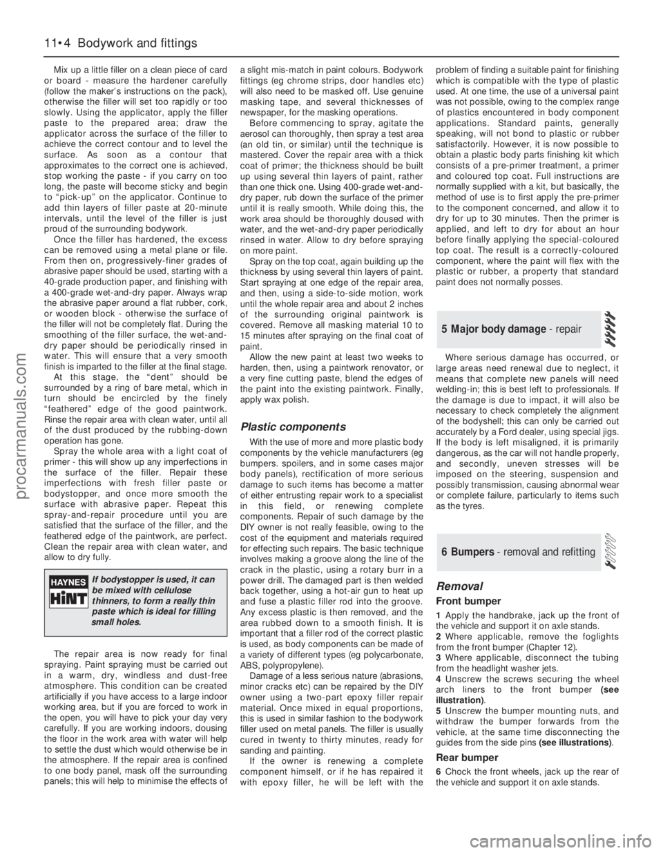
4Unscrew the screws securing the wheel
arch liners to the front bumper (see
illustration).
5Unscrew the bumper mounting nuts, and
withdraw the bumper forwards from the
vehicle, at the same time disconnecting the
guides from the side pins (see illustrations).
Rear bumper
6Chock the front wheels, jack up the rear of
the vehicle and support it on axle stands.
6 Bumpers - removal and refitting
5 Major body damage - repair
11•4 Bodywork and fittings
If bodystopper is used, it can
be mixed with cellulose
thinners, to form a really thin
paste which is ideal for filling
small holes.
procarmanuals.com
Page 223 of 279
1A compact disc (CD) player is available as
an optional extra on most models. On some
models, an autochanger version is available,
which can hold a number of discs at a time.
Removal
2The battery negative (earth) lead should be
disconnected before commencing work.
CD player, or autochanger control
unit
3The procedure is identical to that for the
radio/cassette player described in Section 23.
CD player autochanger
4The CD player autochanger unit is mounted
on the right-hand side of the luggage
compartment. The wiring loom passes up the
“C” pillar, across to the left-hand side “A”
pillar, then to the centre console area.
5Remove the trim cover from the
autochanger unit.
6Unscrew the mounting screws, and remove
the autochanger unit from its mounting
bracket.
7Disconnect the multi-plug and remove the
unit from inside the vehicle.
Refitting
8Refitting is a reversal of the removal
procedure.
Removal
1Remove the door trim panel as described in
Chapter 11.
2Unscrew the cross-head screws, and
withdraw the speaker from the door inner
panel.
3Disconnect the wiring and remove the
speaker.
Refitting
4Refitting is a reversal of the removal
procedure.
Removal
1Prise out the trim cover from the headlining
immediately below the base of the aerial.
2Unscrew the cross-head screw from the
base of the aerial, and remove the aerial mast.
Refitting
3Refitting is a reversal of the removal
procedure.
Warning: Handle the air bag unit
with extreme care, as a
precaution against personal
injury, and always hold it with the
cover facing away from the body. If in
doubt concerning any proposed work
involving the air bag unit or its control
circuitry, consult a Ford dealer or other
qualified specialist.
Removal
1Disconnect the battery negative (earth) lead
(refer to Chapter 5, Section 1).
Warning: Before proceeding, wait
a minimum of 15 minutes, as a
precaution against accidental
firing of the air bag unit. This
period ensures that any stored energy in
the back-up capacitor is dissipated.
2Rotate the steering wheel so that one of the
mounting bolt holes is visible above the
steering column upper shroud.
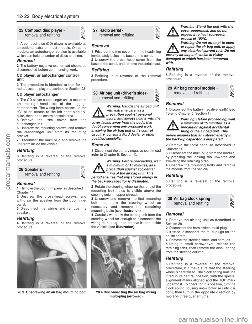
3Unscrew and remove the first mounting
bolt, then turn the steering wheel as
necessary and remove the remaining
mounting bolts (see illustration).
4Carefully withdraw the air bag unit from the
steering wheel far enough to disconnect the
wiring multi-plug, then remove it from inside
the vehicle (see illustration). Warning: Stand the unit with the
cover uppermost, and do not
expose it to heat sources in
excess of 100ºC.
Warning: Do not attempt to open
or repair the air bag unit, or apply
any electrical current to it. Do not
use any air bag unit which is visibly
damaged or which has been tampered
with.
Refitting
5Refitting is a reversal of the removal
procedure.
Removal
1Disconnect the battery negative (earth) lead
(refer to Chapter 5, Section 1).
Warning: Before proceeding, wait
a minimum of 15 minutes, as a
precaution against accidental
firing of the air bag unit. This
period ensures that any stored energy in
the back-up capacitor is dissipated.
2Remove the facia panel as described in
Chapter 11.
3Disconnect the multi-plug from the module,
by pressing the locking tab upwards and
swivelling the retaining strap.
4Unscrew the mounting bolts and remove
the module from the vehicle.
Refitting
5Refitting is a reversal of the removal
procedure.
Removal
1Remove the air bag unit as described in
Section 28.
2Disconnect the horn switch multi-plug.
3If fitted, disconnect the multi-plugs for the
cruise control.
4Remove the steering wheel and shrouds.
5Using a small screwdriver, release the
retaining tabs, then remove the clock spring
from the steering column.
Refitting
6Refitting is a reversal of the removal
procedure, but make sure that the steering
wheel is centralised. The clock spring must be
fitted in its central position, with the special
alignment marks aligned and the TOP mark
uppermost. To check for this position, turn the
clock spring housing anti-clockwise until it is
tight, then turn in the opposite direction by
two-and-three-quarter turns.
30 Air bag clock spring-
removal and refitting
29 Air bag control module -
removal and refitting
28 Air bag unit (driver’s side) -
removal and refitting
27 Radio aerial -
removal and refitting
26 Speakers -
removal and refitting
25 Compact disc player -
removal and refitting
12•22 Body electrical system
28.3 Unscrewing an air bag mounting bolt28.4 Disconnecting the air bag wiring
multi-plug (arrowed)
procarmanuals.com
Page 269 of 279
6 Automatic transmission
REF•10Fault Finding
Note:Due to the complexity of the automatic transmission and its
electronic control system, it is difficult for the home mechanic to
properly diagnose and service this unit. For problems other than the
following, the vehicle should be taken to a dealer service department
or automatic transmission specialist.
Fluid leakage
m mAutomatic transmission fluid is usually deep red in colour. Fluid
leaks should not be confused with engine oil, which can easily be
blown onto the transmission by airflow.
m mTo determine the source of a leak, first remove all built-up dirt and
grime from the transmission housing and surrounding areas, using
a degreasing agent, or by steam-cleaning. Drive the vehicle at low
speed, so airflow will not blow the leak far from its source. Raise
and support the vehicle, and determine where the leak is coming
from. The following are common areas of leakage:
(a) Housing joints (Chapters 1 and 7, Part B).
(b) Dipstick tube (Chapters 1 and 7, Part B).
(c) Transmission-to-fluid cooler pipes/unions (Chapters 3 and 7,
Part B).
(d) Speedometer drive pinion O-ring (Chapter 7, Part B).
(e) Differential side gear oil seals (Chapter 7, Part B).
Transmission fluid brown, or has burned smell
m mTransmission fluid level low, or fluid in need of renewal (Chapter 1).
Transmission will not downshift (kickdown) with
accelerator pedal fully depressed
m mLow transmission fluid level (Chapter 1).
m mIncorrect selector cable adjustment (Chapter 7, Part B).
m mEngine management system fault (Chapters 1, 4, 5 and 6).
General gear selection problems
m
mChapter 7, Part B, deals with checking and adjusting the selector
cable on automatic transmissions. The following are common
problems which may be caused by a poorly-adjusted cable:
(a) Engine starting in gears other than Park or Neutral.
(b) Indicator on gear selector lever pointing to a gear other than the
one actually being used.
(c) Vehicle moves when in Park or Neutral.
(d) Poor gear shift quality or erratic gear changes.
Refer to Chapter 7, Part B for the selector cable adjustment
procedure.
Engine will not start in any gear, or starts in gears
other than Park or Neutral
m mIncorrect selector lever position sensor adjustment (Chapter 7,
Part B).
m mIncorrect selector cable adjustment (Chapter 7, Part B).
Transmission slips, shifts roughly, is noisy, or has no
drive in forward or reverse gears
m mThere are many probable causes for the above problems, but the
home mechanic should be concerned with only one possibility -
fluid level. Before taking the vehicle to a dealer or transmission
specialist, check the fluid level and condition of the fluid as
described in Chapter 1. Correct the fluid level as necessary, or
change the fluid if needed. If the problem persists, professional
help will be necessary.
7 Driveshafts
Clicking or knocking noise on turns (at slow speed
on full-lock)
m mLack of constant velocity joint lubricant (Chapter 8).
m mWorn outer constant velocity joint (Chapter 8).
Vibration when accelerating or decelerating
m
mWorn inner constant velocity joint (Chapter 8).
m mBent or distorted driveshaft (Chapter 8).
8 Braking system
Note:Before assuming that a brake problem exists, make sure that the tyres are in good condition and correctly inflated, that the front wheel
alignment is correct, and that the vehicle is not loaded with weight in an unequal manner. Apart from checking the condition of all pipe and hose
connections, any faults occurring on the Anti-lock Braking System (ABS) should be referred to a Ford dealer for diagnosis - the same applies to the
components of the Traction Control System (TCS).
Vehicle pulls to one side under braking
m mWorn, defective, damaged or contaminated front or rear brake
pads/shoes on one side (Chapter 1).
m mSeized or partially-seized front or rear brake caliper/wheel cylinder
piston (Chapter 9).
m mA mixture of brake pad/shoe lining materials fitted between sides
(Chapter 1).
m mBrake caliper mounting bolts loose (Chapter 9).
m mRear brake backplate mounting bolts loose (Chapter 9).
m mWorn or damaged steering or suspension components (Chap-
ter 10).
Noise (grinding or high-pitched squeal) when brakes
applied
m mBrake pad or shoe friction lining material worn down to metal
backing (Chapter 1).
m mExcessive corrosion of brake disc or drum (may be apparent after
the vehicle has been standing for some time) (Chapter 1).
m mForeign object (stone chipping, etc) trapped between brake disc
and splash shield (Chapter 1).
Excessive brake pedal travel
m mInoperative rear brake self-adjust mechanism (Chapter 9).
m mFaulty master cylinder (Chapter 9).
m mAir in hydraulic system (Chapter 9).
procarmanuals.com
Page 270 of 279
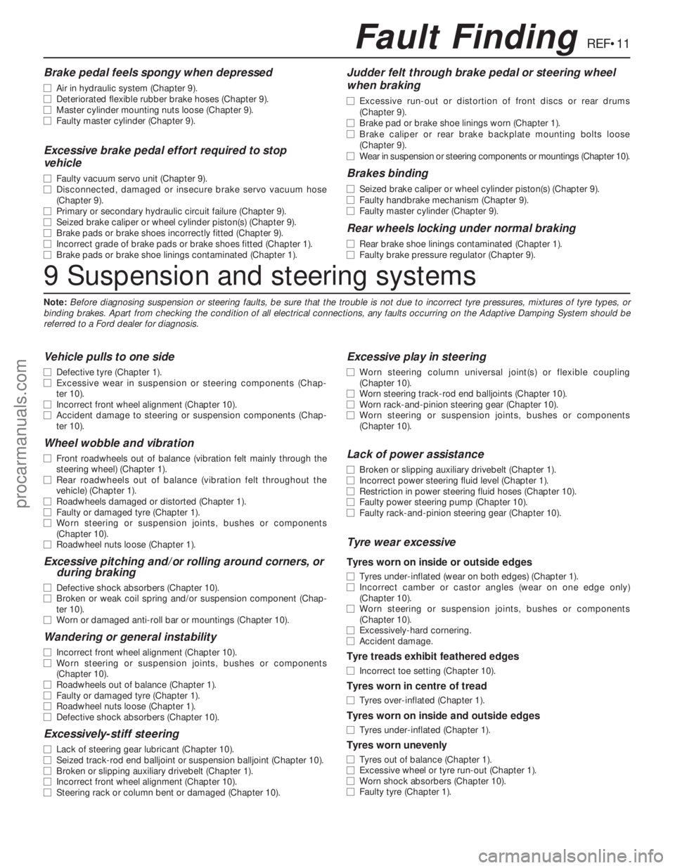
REF•11Fault Finding
9 Suspension and steering systems
Note:Before diagnosing suspension or steering faults, be sure that the trouble is not due to incorrect tyre pressures, mixtures of tyre types, or
binding brakes. Apart from checking the condition of all electrical connections, any faults occurring on the Adaptive Damping System should be
referred to a Ford dealer for diagnosis.
Vehicle pulls to one side
m mDefective tyre (Chapter 1).
m mExcessive wear in suspension or steering components (Chap-
ter 10).
m mIncorrect front wheel alignment (Chapter 10).
m mAccident damage to steering or suspension components (Chap-
ter 10).
Wheel wobble and vibration
m mFront roadwheels out of balance (vibration felt mainly through the
steering wheel) (Chapter 1).
m mRear roadwheels out of balance (vibration felt throughout the
vehicle) (Chapter 1).
m mRoadwheels damaged or distorted (Chapter 1).
m mFaulty or damaged tyre (Chapter 1).
m mWorn steering or suspension joints, bushes or components
(Chapter 10).
m mRoadwheel nuts loose (Chapter 1).
Excessive pitching and/or rolling around corners, or
during braking
m mDefective shock absorbers (Chapter 10).
m mBroken or weak coil spring and/or suspension component (Chap-
ter 10).
m mWorn or damaged anti-roll bar or mountings (Chapter 10).
Wandering or general instability
m
mIncorrect front wheel alignment (Chapter 10).
m mWorn steering or suspension joints, bushes or components
(Chapter 10).
m mRoadwheels out of balance (Chapter 1).
m mFaulty or damaged tyre (Chapter 1).
m mRoadwheel nuts loose (Chapter 1).
m mDefective shock absorbers (Chapter 10).
Excessively-stiff steering
m
mLack of steering gear lubricant (Chapter 10).
m mSeized track-rod end balljoint or suspension balljoint (Chapter 10).
m mBroken or slipping auxiliary drivebelt (Chapter 1).
m mIncorrect front wheel alignment (Chapter 10).
m mSteering rack or column bent or damaged (Chapter 10).
Excessive play in steering
m
mWorn steering column universal joint(s) or flexible coupling
(Chapter 10).
m mWorn steering track-rod end balljoints (Chapter 10).
m mWorn rack-and-pinion steering gear (Chapter 10).
m mWorn steering or suspension joints, bushes or components
(Chapter 10).
Lack of power assistance
m mBroken or slipping auxiliary drivebelt (Chapter 1).
m mIncorrect power steering fluid level (Chapter 1).
m mRestriction in power steering fluid hoses (Chapter 10).
m mFaulty power steering pump (Chapter 10).
m mFaulty rack-and-pinion steering gear (Chapter 10).
Tyre wear excessive
Tyres worn on inside or outside edges
m
mTyres under-inflated (wear on both edges) (Chapter 1).
m mIncorrect camber or castor angles (wear on one edge only)
(Chapter 10).
m mWorn steering or suspension joints, bushes or components
(Chapter 10).
m mExcessively-hard cornering.
m mAccident damage.
Tyre treads exhibit feathered edges
m
mIncorrect toe setting (Chapter 10).
Tyres worn in centre of tread
m
mTyres over-inflated (Chapter 1).
Tyres worn on inside and outside edges
m
mTyres under-inflated (Chapter 1).
Tyres worn unevenly
m
mTyres out of balance (Chapter 1).
m mExcessive wheel or tyre run-out (Chapter 1).
m mWorn shock absorbers (Chapter 10).
m mFaulty tyre (Chapter 1).
Brake pedal feels spongy when depressed
m
mAir in hydraulic system (Chapter 9).
m mDeteriorated flexible rubber brake hoses (Chapter 9).
m mMaster cylinder mounting nuts loose (Chapter 9).
m mFaulty master cylinder (Chapter 9).
Excessive brake pedal effort required to stop
vehicle
m mFaulty vacuum servo unit (Chapter 9).
m mDisconnected, damaged or insecure brake servo vacuum hose
(Chapter 9).
m mPrimary or secondary hydraulic circuit failure (Chapter 9).
m mSeized brake caliper or wheel cylinder piston(s) (Chapter 9).
m mBrake pads or brake shoes incorrectly fitted (Chapter 9).
m mIncorrect grade of brake pads or brake shoes fitted (Chapter 1).
m mBrake pads or brake shoe linings contaminated (Chapter 1).
Judder felt through brake pedal or steering wheel
when braking
m mExcessive run-out or distortion of front discs or rear drums
(Chapter 9).
m mBrake pad or brake shoe linings worn (Chapter 1).
m mBrake caliper or rear brake backplate mounting bolts loose
(Chapter 9).
m mWear in suspension or steering components or mountings (Chapter 10).
Brakes binding
m
mSeized brake caliper or wheel cylinder piston(s) (Chapter 9).
m mFaulty handbrake mechanism (Chapter 9).
m mFaulty master cylinder (Chapter 9).
Rear wheels locking under normal braking
m
mRear brake shoe linings contaminated (Chapter 1).
m mFaulty brake pressure regulator (Chapter 9).
procarmanuals.com
Page 272 of 279
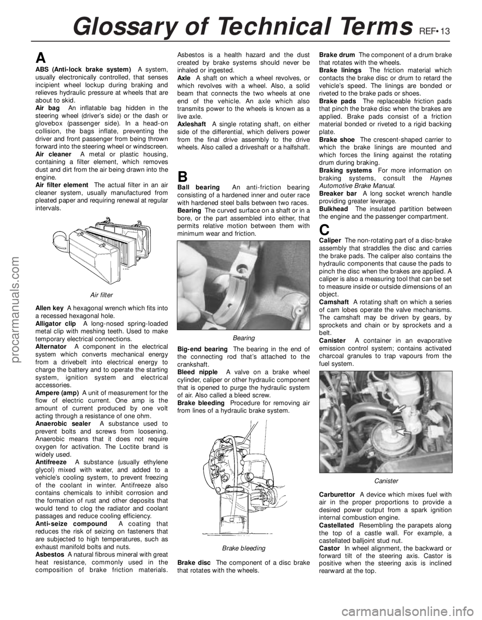
REF•13Glossary of Technical Terms
A
ABS (Anti-lock brake system)A system,
usually electronically controlled, that senses
incipient wheel lockup during braking and
relieves hydraulic pressure at wheels that are
about to skid.
Air bag An inflatable bag hidden in the
steering wheel (driver’s side) or the dash or
glovebox (passenger side). In a head-on
collision, the bags inflate, preventing the
driver and front passenger from being thrown
forward into the steering wheel or windscreen.
Air cleanerA metal or plastic housing,
containing a filter element, which removes
dust and dirt from the air being drawn into the
engine.
Air filter elementThe actual filter in an air
cleaner system, usually manufactured from
pleated paper and requiring renewal at regular
intervals.
Allen keyA hexagonal wrench which fits into
a recessed hexagonal hole.
Alligator clipA long-nosed spring-loaded
metal clip with meshing teeth. Used to make
temporary electrical connections.
AlternatorA component in the electrical
system which converts mechanical energy
from a drivebelt into electrical energy to
charge the battery and to operate the starting
system, ignition system and electrical
accessories.
Ampere (amp)A unit of measurement for the
flow of electric current. One amp is the
amount of current produced by one volt
acting through a resistance of one ohm.
Anaerobic sealerA substance used to
prevent bolts and screws from loosening.
Anaerobic means that it does not require
oxygen for activation. The Loctite brand is
widely used.
AntifreezeA substance (usually ethylene
glycol) mixed with water, and added to a
vehicle’s cooling system, to prevent freezing
of the coolant in winter. Antifreeze also
contains chemicals to inhibit corrosion and
the formation of rust and other deposits that
would tend to clog the radiator and coolant
passages and reduce cooling efficiency.
Anti-seize compoundA coating that
reduces the risk of seizing on fasteners that
are subjected to high temperatures, such as
exhaust manifold bolts and nuts.
AsbestosA natural fibrous mineral with great
heat resistance, commonly used in the
composition of brake friction materials.Asbestos is a health hazard and the dust
created by brake systems should never be
inhaled or ingested.
AxleA shaft on which a wheel revolves, or
which revolves with a wheel. Also, a solid
beam that connects the two wheels at one
end of the vehicle. An axle which also
transmits power to the wheels is known as a
live axle.
AxleshaftA single rotating shaft, on either
side of the differential, which delivers power
from the final drive assembly to the drive
wheels. Also called a driveshaft or a halfshaft.
BBall bearingAn anti-friction bearing
consisting of a hardened inner and outer race
with hardened steel balls between two races.
BearingThe curved surface on a shaft or in a
bore, or the part assembled into either, that
permits relative motion between them with
minimum wear and friction.
Big-end bearingThe bearing in the end of
the connecting rod that’s attached to the
crankshaft.
Bleed nippleA valve on a brake wheel
cylinder, caliper or other hydraulic component
that is opened to purge the hydraulic system
of air. Also called a bleed screw.
Brake bleedingProcedure for removing air
from lines of a hydraulic brake system.
Brake discThe component of a disc brake
that rotates with the wheels.Brake drumThe component of a drum brake
that rotates with the wheels.
Brake liningsThe friction material which
contacts the brake disc or drum to retard the
vehicle’s speed. The linings are bonded or
riveted to the brake pads or shoes.
Brake padsThe replaceable friction pads
that pinch the brake disc when the brakes are
applied. Brake pads consist of a friction
material bonded or riveted to a rigid backing
plate.
Brake shoeThe crescent-shaped carrier to
which the brake linings are mounted and
which forces the lining against the rotating
drum during braking.
Braking systemsFor more information on
braking systems, consult the Haynes
Automotive Brake Manual.
Breaker barA long socket wrench handle
providing greater leverage.
BulkheadThe insulated partition between
the engine and the passenger compartment.
CCaliperThe non-rotating part of a disc-brake
assembly that straddles the disc and carries
the brake pads. The caliper also contains the
hydraulic components that cause the pads to
pinch the disc when the brakes are applied. A
caliper is also a measuring tool that can be set
to measure inside or outside dimensions of an
object.
CamshaftA rotating shaft on which a series
of cam lobes operate the valve mechanisms.
The camshaft may be driven by gears, by
sprockets and chain or by sprockets and a
belt.
CanisterA container in an evaporative
emission control system; contains activated
charcoal granules to trap vapours from the
fuel system.
CarburettorA device which mixes fuel with
air in the proper proportions to provide a
desired power output from a spark ignition
internal combustion engine.
CastellatedResembling the parapets along
the top of a castle wall. For example, a
castellated balljoint stud nut.
CastorIn wheel alignment, the backward or
forward tilt of the steering axis. Castor is
positive when the steering axis is inclined
rearward at the top.
Canister
Brake bleeding
Bearing
Air filter
procarmanuals.com
Page 278 of 279
REF•19Index
Oil pressure warning light switch - 2A•22
Oil pump - 2A•21
Oil seals - 2A•13, 2A•22, 7A•2, 7B•3, REF•4
Oil separator - 6•19
Open-circuit - 12•4
Overcooling - REF•8
Overhead console - 11•22
Overheating - REF•8
Oxygen sensor - 6•11, 6•12, 6•13
P
Pads - 9•3, 9•8
Pedals - 1•17, 4•5, 8•3, 9•10, 9•11
Piston rings - 2B•19
Pistons - 2B•12, 2B•17, 2B•21, 2B•22
Pitching and/or rolling around corners -
REF•11
Plastic components - 11•4
Plenum chamber - 4•3
Poisonous or irritant substances - 0•5
Pollen filter - 1•20, 3•8
Position sensor - 5•4, 6•10, 6•11, 6•12
Positive Crankcase Ventilation (PCV)
system - 1•23, 6•18, 6•19
Power steering - 1•8, 1•10, 6•11, 6•12,
6•13, 10•20, 10•21, 10•22
Power steering fluid - 1•2
Pressure-control relief valve - 9•13
Pressure-cycling and pressure-regulating
switches - 3•10
Project vehicles - 0•4
Pulse-air - 6•17, 6•18
Purge solenoid valve - 6•14
R
Radiator - 3•4, 3•5
Radiator grille - 11•5
Radio - 12•21, 12•22
Radio aerial - 12•22
Reading light - 12•11
Rear light cluster - 12•9, 12•13
Rear window - 12•8, 12•21
Relays - 12•5
Repair procedures - REF•4
Resonator (engine compartment) - 4•3
Respraying - 11•3
Reversing light switch - 7A•3
Road test - 1•20
Roadwheels - 1•17, 1•18, 1•20
Roll-over valves - 4•8
Routine maintenance and servicing- 1•1et
seq
Rubber gaiters- 1•18, 8•7, 8•9, 10•21
Rust holes in bodywork - 11•3
S
Safety first! - 0•5
Scalding - 0•5
Scratches in bodywork - 11•3
Screw threads and fastenings - REF•4
Seat belts - 0•8, 1•13, 11•19, 11•20Seats - 0•8, 11•18, 12•8
Selector assembly - 7B•2
Selector cable - 7B•2
Selector lever position sensor - 7B•2
Selector panel illumination - 12•11
Service indicator - 12•17, 12•18
Servo unit - 9•12, 9•13
Shock absorbers - 0•8, 0•9, 10•14
Shoes - 9•6
Short-circuit - 12•4
Sidelight - 12•9
Solenoid renewal - 5•8
Spare parts - REF•5
Spark plugs - 1•23
Speakers - 12•22
Speed control - 12•20
Speed sensor - 6•11, 6•12, 6•13
Speedometer - 7A•2, 7A•3, 7B•2, 7B•3,
12•15
Springs - 0•9
Starter motor - 5•7
Starter motor fault - REF•7
Starting system - 5•6
Steering - 0•7, 0•8, 0•9, 1•17, 1•20
Steering angles - 10•22
Steering column - 10•18, 10•20
Steering fault - REF•11
Steering knuckle - 10•5
Steering wheel - 10•17
Stop-light switch - 9•15
Striker - 11•13
Struts - 10•6, 10•7, 10•10, 10•12
Sump - 2A•19
Sun visor - 11•20
Sunroof - 11•18, 12•7
Suspension and steering systems- 0•8,
0•9, 1•17, 1•18, 1•20, 10•1et seq
Suspension and steering systems fault
finding - REF•11
Switches - 2A•22, 3•4, 3•5, 3•10, 4•8-
6•11, 6•12, 6•13, 7A•3, 9•15, 11•17,
12•6, 12•7, 12•8, 12•11, 12•18, 12•20
T
Tailgate - 1•8, 1•10, 11•15, 11•16, 12•17,
12•20, REF•12
Tappets - 2A•14
TCS inhibitor switch - 9•15
TCS throttle actuator - 9•15
Temperature gauge fault - REF•12
Thermostat - 3•3, 3•4
Throttle actuator - 9•15
Throttle housing - 4•9
Throttle potentiometer - 6•11, 6•13
Tie-bar - 10•13, 10•16
Timer module - 12•5
Timing - 5•4, 6•10
Timing belt - 1•26, 2A•10, 2A•13
Tools - REF•1, REF•3, REF•4
Top Dead Centre (TDC) for No 1 piston -
2A•6
Towing - 0•11
Track rod end - 10•22Traction Control System - 9•15, 12•7
Transmission- 1•11, 1•17, 2A•24, 2B•3,
2B•4, 7A•1 et seq, 7B•1 et seq, 12•11
Trim mouldings - 11•17
Trim panels - 11•6, 11•20
Trip computer - 12•17
Tyre wear - REF•11
Tyres - 0•10, 1•8
U
Underbody check - 1•19
Upper suspension arm - 10•16
V
Vacuum hoses - 1•15
Vacuum servo unit - 9•12, 9•13
Valve clearances - 2A•5
Valves - 2B•10, 2B•11
Vehicle identification - 0•8, REF•5
Vehicle pulls to one side - REF•10, REF•11
Vehicle speed sensor - 6•11, 6•12, 6•13
Ventilation system - 1•20, 3•7
Voltage regulator - 5•6
W
Warning lights - 12•11
Warning system - 12•17
Washer jets fault - REF•12
Washer nozzle - 12•21
Washer pump fault - REF•12
Washer reservoir and pump - 12•20
Washer system - 1•8, 1•10, 12•18, 12•20
Water pump - 3•6
Weights - 0•6
Wheel alignment - 10•22
Wheel arch liner - 11•24
Wheel bearings - 0•9
Wheel changing - 0•11
Wheel cylinders - 9•8
Wheel sensors - 9•14
Wheel wobble - REF•11
Wheels - 0•10, 1•17, 1•18, 1•20
Wheels locking - REF•11
Window glass - 11•8
Window regulator - 11•9
Windows - 11•17, 12•7, 12•8, 12•21,
REF•12
Windscreen - 0•7, 1•8, 1•10, 11•17, 12•6,
12•8, 12•16, 12•20, 12•21, REF•12
Wiper arms - 12•16
Wiper blade - 1•10
Wiper blade fault - REF•12
Wiper motor - 12•16, 12•17
Wipers - 12•6
Wiper fault - REF•12
Wiring - 1•15
Wiring diagrams- 12•23et seq
Working facilities - REF•3
procarmanuals.com