1993 FORD MONDEO parking brake
[x] Cancel search: parking brakePage 32 of 279
of these components will cause loss of
lubricant, together with dirt and water entry,
resulting in rapid deterioration of the balljoints
or steering gear.
3Check the power-assisted steering fluid
hoses for chafing or deterioration, and the
pipe and hose unions for fluid leaks. Also
check for signs of fluid leakage under
pressure from the steering gear rubber
gaiters, which would indicate failed fluid seals
within the steering gear.
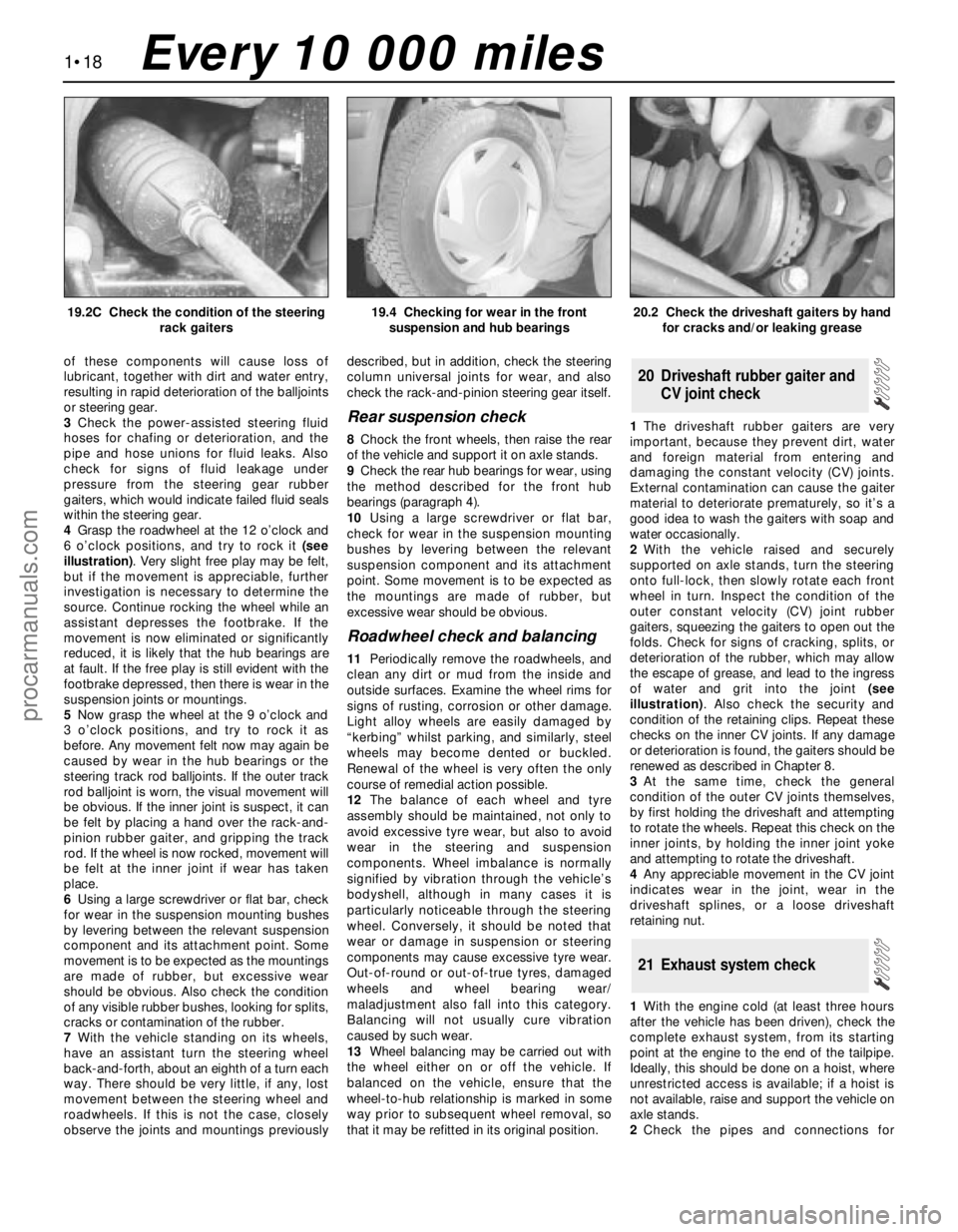
4Grasp the roadwheel at the 12 o’clock and
6 o’clock positions, and try to rock it (see
illustration). Very slight free play may be felt,
but if the movement is appreciable, further
investigation is necessary to determine the
source. Continue rocking the wheel while an
assistant depresses the footbrake. If the
movement is now eliminated or significantly
reduced, it is likely that the hub bearings are
at fault. If the free play is still evident with the
footbrake depressed, then there is wear in the
suspension joints or mountings.
5Now grasp the wheel at the 9 o’clock and
3 o’clock positions, and try to rock it as
before. Any movement felt now may again be
caused by wear in the hub bearings or the
steering track rod balljoints. If the outer track
rod balljoint is worn, the visual movement will
be obvious. If the inner joint is suspect, it can
be felt by placing a hand over the rack-and-
pinion rubber gaiter, and gripping the track
rod. If the wheel is now rocked, movement will
be felt at the inner joint if wear has taken
place.
6Using a large screwdriver or flat bar, check
for wear in the suspension mounting bushes
by levering between the relevant suspension
component and its attachment point. Some
movement is to be expected as the mountings
are made of rubber, but excessive wear
should be obvious. Also check the condition
of any visible rubber bushes, looking for splits,
cracks or contamination of the rubber.
7With the vehicle standing on its wheels,
have an assistant turn the steering wheel
back-and-forth, about an eighth of a turn each
way. There should be very little, if any, lost
movement between the steering wheel and
roadwheels. If this is not the case, closely
observe the joints and mountings previouslydescribed, but in addition, check the steering
column universal joints for wear, and also
check the rack-and-pinion steering gear itself.
Rear suspension check
8Chock the front wheels, then raise the rear
of the vehicle and support it on axle stands.
9Check the rear hub bearings for wear, using
the method described for the front hub
bearings (paragraph 4).
10Using a large screwdriver or flat bar,
check for wear in the suspension mounting
bushes by levering between the relevant
suspension component and its attachment
point. Some movement is to be expected as
the mountings are made of rubber, but
excessive wear should be obvious.
Roadwheel check and balancing
11Periodically remove the roadwheels, and
clean any dirt or mud from the inside and
outside surfaces. Examine the wheel rims for
signs of rusting, corrosion or other damage.
Light alloy wheels are easily damaged by
“kerbing” whilst parking, and similarly, steel
wheels may become dented or buckled.
Renewal of the wheel is very often the only
course of remedial action possible.
12The balance of each wheel and tyre
assembly should be maintained, not only to
avoid excessive tyre wear, but also to avoid
wear in the steering and suspension
components. Wheel imbalance is normally
signified by vibration through the vehicle’s
bodyshell, although in many cases it is
particularly noticeable through the steering
wheel. Conversely, it should be noted that
wear or damage in suspension or steering
components may cause excessive tyre wear.
Out-of-round or out-of-true tyres, damaged
wheels and wheel bearing wear/
maladjustment also fall into this category.
Balancing will not usually cure vibration
caused by such wear.
13Wheel balancing may be carried out with
the wheel either on or off the vehicle. If
balanced on the vehicle, ensure that the
wheel-to-hub relationship is marked in some
way prior to subsequent wheel removal, so
that it may be refitted in its original position.1The driveshaft rubber gaiters are very
important, because they prevent dirt, water
and foreign material from entering and
damaging the constant velocity (CV) joints.
External contamination can cause the gaiter
material to deteriorate prematurely, so it’s a
good idea to wash the gaiters with soap and
water occasionally.
2With the vehicle raised and securely
supported on axle stands, turn the steering
onto full-lock, then slowly rotate each front
wheel in turn. Inspect the condition of the
outer constant velocity (CV) joint rubber
gaiters, squeezing the gaiters to open out the
folds. Check for signs of cracking, splits, or
deterioration of the rubber, which may allow
the escape of grease, and lead to the ingress
of water and grit into the joint (see
illustration). Also check the security and
condition of the retaining clips. Repeat these
checks on the inner CV joints. If any damage
or deterioration is found, the gaiters should be
renewed as described in Chapter 8.
3At the same time, check the general
condition of the outer CV joints themselves,
by first holding the driveshaft and attempting
to rotate the wheels. Repeat this check on the
inner joints, by holding the inner joint yoke
and attempting to rotate the driveshaft.
4Any appreciable movement in the CV joint
indicates wear in the joint, wear in the
driveshaft splines, or a loose driveshaft
retaining nut.
1With the engine cold (at least three hours
after the vehicle has been driven), check the
complete exhaust system, from its starting
point at the engine to the end of the tailpipe.
Ideally, this should be done on a hoist, where
unrestricted access is available; if a hoist is
not available, raise and support the vehicle on
axle stands.
2Check the pipes and connections for
21 Exhaust system check
20 Driveshaft rubber gaiter and
CV joint check
1•18
19.2C Check the condition of the steering
rack gaiters19.4 Checking for wear in the front
suspension and hub bearings20.2 Check the driveshaft gaiters by hand
for cracks and/or leaking grease
Every 10 000 miles
procarmanuals.com
Page 273 of 279
REF•14Glossary of Technical Terms
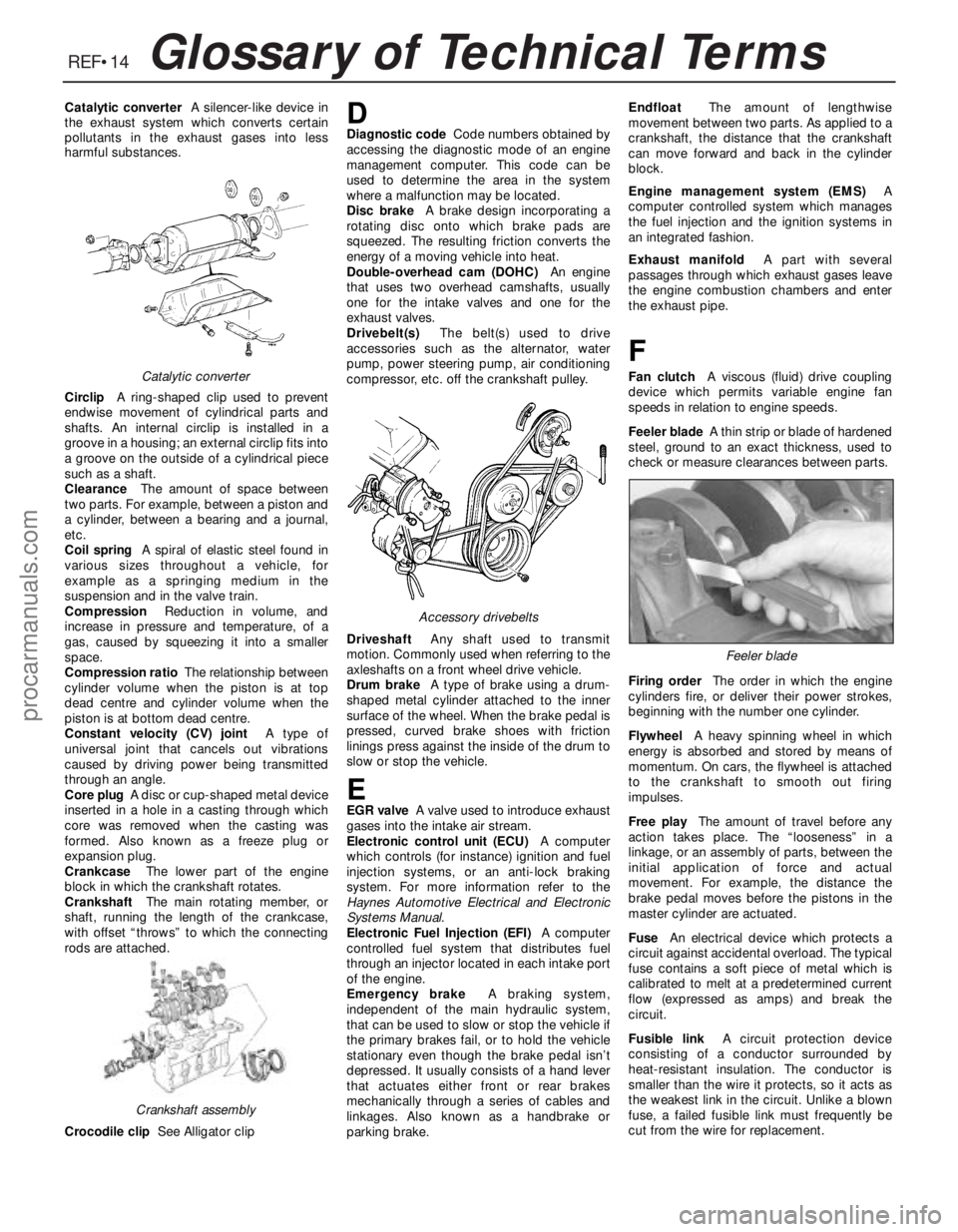
Catalytic converterA silencer-like device in
the exhaust system which converts certain
pollutants in the exhaust gases into less
harmful substances.
CirclipA ring-shaped clip used to prevent
endwise movement of cylindrical parts and
shafts. An internal circlip is installed in a
groove in a housing; an external circlip fits into
a groove on the outside of a cylindrical piece
such as a shaft.
ClearanceThe amount of space between
two parts. For example, between a piston and
a cylinder, between a bearing and a journal,
etc.
Coil springA spiral of elastic steel found in
various sizes throughout a vehicle, for
example as a springing medium in the
suspension and in the valve train.
CompressionReduction in volume, and
increase in pressure and temperature, of a
gas, caused by squeezing it into a smaller
space.
Compression ratioThe relationship between
cylinder volume when the piston is at top
dead centre and cylinder volume when the
piston is at bottom dead centre.
Constant velocity (CV) jointA type of
universal joint that cancels out vibrations
caused by driving power being transmitted
through an angle.
Core plugA disc or cup-shaped metal device
inserted in a hole in a casting through which
core was removed when the casting was
formed. Also known as a freeze plug or
expansion plug.
CrankcaseThe lower part of the engine
block in which the crankshaft rotates.
CrankshaftThe main rotating member, or
shaft, running the length of the crankcase,
with offset “throws” to which the connecting
rods are attached.
Crocodile clipSee Alligator clipDDiagnostic codeCode numbers obtained by
accessing the diagnostic mode of an engine
management computer. This code can be
used to determine the area in the system
where a malfunction may be located.
Disc brakeA brake design incorporating a
rotating disc onto which brake pads are
squeezed. The resulting friction converts the
energy of a moving vehicle into heat.
Double-overhead cam (DOHC)An engine
that uses two overhead camshafts, usually
one for the intake valves and one for the
exhaust valves.
Drivebelt(s)The belt(s) used to drive
accessories such as the alternator, water
pump, power steering pump, air conditioning
compressor, etc. off the crankshaft pulley.
DriveshaftAny shaft used to transmit
motion. Commonly used when referring to the
axleshafts on a front wheel drive vehicle.
Drum brakeA type of brake using a drum-
shaped metal cylinder attached to the inner
surface of the wheel. When the brake pedal is
pressed, curved brake shoes with friction
linings press against the inside of the drum to
slow or stop the vehicle.
EEGR valveA valve used to introduce exhaust
gases into the intake air stream.
Electronic control unit (ECU)A computer
which controls (for instance) ignition and fuel
injection systems, or an anti-lock braking
system. For more information refer to the
Haynes Automotive Electrical and Electronic
Systems Manual.
Electronic Fuel Injection (EFI)A computer
controlled fuel system that distributes fuel
through an injector located in each intake port
of the engine.
Emergency brakeA braking system,
independent of the main hydraulic system,
that can be used to slow or stop the vehicle if
the primary brakes fail, or to hold the vehicle
stationary even though the brake pedal isn’t
depressed. It usually consists of a hand lever
that actuates either front or rear brakes
mechanically through a series of cables and
linkages. Also known as a handbrake or
parking brake.EndfloatThe amount of lengthwise
movement between two parts. As applied to a
crankshaft, the distance that the crankshaft
can move forward and back in the cylinder
block.
Engine management system (EMS)A
computer controlled system which manages
the fuel injection and the ignition systems in
an integrated fashion.
Exhaust manifoldA part with several
passages through which exhaust gases leave
the engine combustion chambers and enter
the exhaust pipe.
F
Fan clutchA viscous (fluid) drive coupling
device which permits variable engine fan
speeds in relation to engine speeds.
Feeler bladeA thin strip or blade of hardened
steel, ground to an exact thickness, used to
check or measure clearances between parts.
Firing orderThe order in which the engine
cylinders fire, or deliver their power strokes,
beginning with the number one cylinder.
Flywheel A heavy spinning wheel in which
energy is absorbed and stored by means of
momentum. On cars, the flywheel is attached
to the crankshaft to smooth out firing
impulses.
Free playThe amount of travel before any
action takes place. The “looseness” in a
linkage, or an assembly of parts, between the
initial application of force and actual
movement. For example, the distance the
brake pedal moves before the pistons in the
master cylinder are actuated.
FuseAn electrical device which protects a
circuit against accidental overload. The typical
fuse contains a soft piece of metal which is
calibrated to melt at a predetermined current
flow (expressed as amps) and break the
circuit.
Fusible linkA circuit protection device
consisting of a conductor surrounded by
heat-resistant insulation. The conductor is
smaller than the wire it protects, so it acts as
the weakest link in the circuit. Unlike a blown
fuse, a failed fusible link must frequently be
cut from the wire for replacement.Catalytic converter
Crankshaft assembly
Accessory drivebelts
Feeler blade
procarmanuals.com