1993 FORD MONDEO flat tire
[x] Cancel search: flat tirePage 28 of 279
being felt when its pulley is rotated clockwise,
and a smooth return to the limit of its travel
when released.
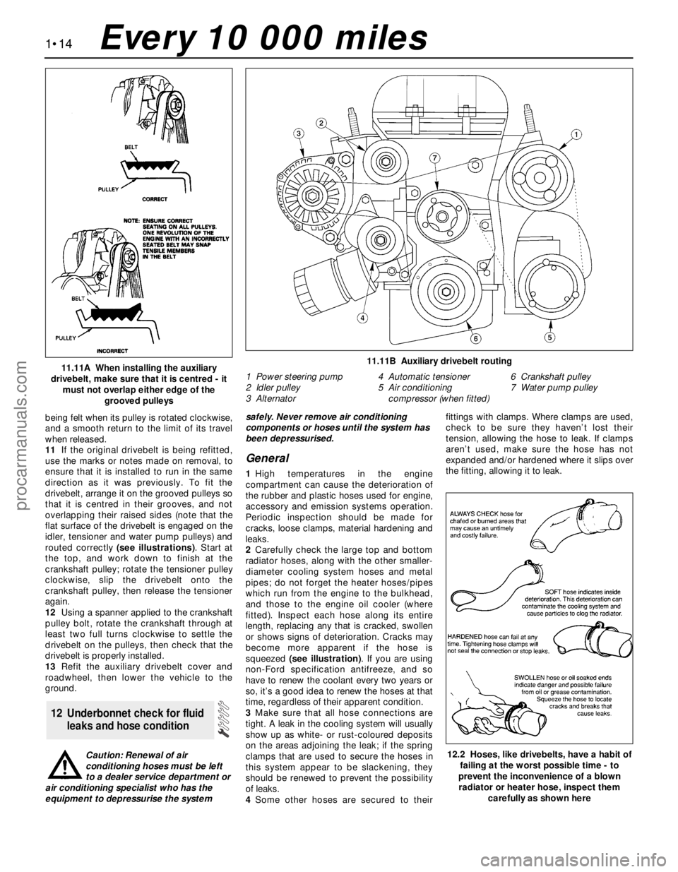
11If the original drivebelt is being refitted,
use the marks or notes made on removal, to
ensure that it is installed to run in the same
direction as it was previously. To fit the
drivebelt, arrange it on the grooved pulleys so
that it is centred in their grooves, and not
overlapping their raised sides (note that the
flat surface of the drivebelt is engaged on the
idler, tensioner and water pump pulleys) and
routed correctly (see illustrations). Start at
the top, and work down to finish at the
crankshaft pulley; rotate the tensioner pulley
clockwise, slip the drivebelt onto the
crankshaft pulley, then release the tensioner
again.
12Using a spanner applied to the crankshaft
pulley bolt, rotate the crankshaft through at
least two full turns clockwise to settle the
drivebelt on the pulleys, then check that the
drivebelt is properly installed.
13Refit the auxiliary drivebelt cover and
roadwheel, then lower the vehicle to the
ground.
Caution: Renewal of air
conditioning hoses must be left
to a dealer service department or
air conditioning specialist who has the
equipment to depressurise the systemsafely. Never remove air conditioning
components or hoses until the system has
been depressurised.
General
1High temperatures in the engine
compartment can cause the deterioration of
the rubber and plastic hoses used for engine,
accessory and emission systems operation.
Periodic inspection should be made for
cracks, loose clamps, material hardening and
leaks.
2Carefully check the large top and bottom
radiator hoses, along with the other smaller-
diameter cooling system hoses and metal
pipes; do not forget the heater hoses/pipes
which run from the engine to the bulkhead,
and those to the engine oil cooler (where
fitted). Inspect each hose along its entire
length, replacing any that is cracked, swollen
or shows signs of deterioration. Cracks may
become more apparent if the hose is
squeezed (see illustration). If you are using
non-Ford specification antifreeze, and so
have to renew the coolant every two years or
so, it’s a good idea to renew the hoses at that
time, regardless of their apparent condition.
3Make sure that all hose connections are
tight. A leak in the cooling system will usually
show up as white- or rust-coloured deposits
on the areas adjoining the leak; if the spring
clamps that are used to secure the hoses in
this system appear to be slackening, they
should be renewed to prevent the possibility
of leaks.
4Some other hoses are secured to theirfittings with clamps. Where clamps are used,
check to be sure they haven’t lost their
tension, allowing the hose to leak. If clamps
aren’t used, make sure the hose has not
expanded and/or hardened where it slips over
the fitting, allowing it to leak.
12 Underbonnet check for fluid
leaks and hose condition
1•14
11.11A When installing the auxiliary
drivebelt, make sure that it is centred - it
must not overlap either edge of the
grooved pulleys11.11B Auxiliary drivebelt routing
1 Power steering pump
2 Idler pulley
3 Alternator4 Automatic tensioner
5 Air conditioning
compressor (when fitted)6 Crankshaft pulley
7 Water pump pulley
12.2 Hoses, like drivebelts, have a habit of
failing at the worst possible time - to
prevent the inconvenience of a blown
radiator or heater hose, inspect them
carefully as shown here
Every 10 000 miles
procarmanuals.com
Page 69 of 279
How to use this Chapter
This Part of Chapter 2 is devoted to
engine/transmission removal and refitting, to
those repair procedures requiring the removal
of the engine/transmission from the vehicle,
and to the overhaul of engine components. It
includes only the Specifications relevant to
those procedures. Refer to Part A for
additional Specifications, if required.
General information
The information ranges from advice
concerning preparation for an overhaul and
the purchase of replacement parts, to detailed
step-by-step procedures covering removal
and installation of internal engine components
and the inspection of parts.
The following Sections have been written
based on the assumption that the engine has
been removed from the vehicle. For
information concerning in-vehicle engine
repair, as well as removal and installation of
the external components necessary for the
overhaul, see Part A of this Chapter and
Section 5 of this Part.
When overhauling this engine, it is essential
to establish first exactly what replacement
parts are available. At the time of writing,
components such as the piston rings are not
available separately from the
piston/connecting rod assemblies; pistons,
gudgeon pins and valve guides are not
available separately, and very few under- or
oversized components are available for
engine reconditioning. In most cases, it would
appear that the easiest and most
economically-sensible course of action is to
replace a worn or damaged engine with an
exchange unit.
It’s not always easy to determine when, or
if, an engine should be completely
overhauled, as a number of factors must be
considered.
High mileage is not necessarily an
indication that an overhaul is needed, while
low mileage doesn’t preclude the need for an
overhaul. Frequency of servicing is probably
the most important consideration. An engine
that’s had regular and frequent oil and filter
changes, as well as other required
maintenance, will most likely give many
thousands of miles of reliable service.
Conversely, a neglected engine may require
an overhaul very early in its life.
Excessive oil consumption is an indication
that piston rings, valve seals and/or valve
guides are in need of attention. Make surethat oil leaks aren’t responsible before
deciding that the rings and/or guides are
worn. Perform a cylinder compression check
(Part A of this Chapter, Section 3) to
determine the extent of the work required.
Loss of power, rough running, knocking or
metallic engine noises, excessive valve train
noise and high fuel consumption rates may
also point to the need for an overhaul,
especially if they’re all present at the same
time. If a full service doesn’t remedy the
situation, major mechanical work is the only
solution.
An engine overhaul involves restoring all
internal parts to the specification of a new
engine. Note:Always check first what
replacement parts are available before
planning any overhaul operation; refer to
Section 1 of this Part. Ford dealers, or a good
engine reconditioning specialist/automotive
parts supplier may be able to suggest
alternatives which will enable you to overcome
the lack of replacement parts.
During an overhaul, it is usual to renew the
piston rings, and to rebore and/or hone the
cylinder bores; where the rebore is done by an
automotive machine shop, new oversize
pistons and rings will also be installed - all
these operations, of course, assume the
availability of suitable replacement parts. The
main and big-end bearings are generally
renewed and, if necessary, the crankshaft
may be reground to restore the journals.
Generally, the valves are serviced as well,
since they’re usually in less-than-perfect
condition at this point. While the engine is
being overhauled, other components, such as
the starter and alternator, can be renewed as
well, or rebuilt, if the necessary parts can be
found. The end result should be an as-new
engine that will give many trouble-free miles.
Note:Critical cooling system components
such as the hoses, drivebelt, thermostat and
water pump MUST be replaced with new
parts when an engine is overhauled. The
radiator should be checked carefully, to
ensure that it isn’t clogged or leaking (see
Chapter 3). Also, as a general rule, the oil
pump should be renewed when an engine is
rebuilt.
Before beginning the engine overhaul, read
through the entire procedure to familiarise
yourself with the scope and requirements of
the job. Overhauling an engine isn’t difficult,
but it is time-consuming. Plan on the vehicle
being off the road for a minimum of two
weeks, especially if parts must be taken to an
automotive machine shop for repair or
reconditioning. Check on availability of parts,
and make sure that any necessary special
tools and equipment are obtained in advance.
Most work can be done with typical hand
tools, although a number of precision
measuring tools are required, for inspecting
parts to determine if they must be replaced.
Often, an automotive machine shop will
handle the inspection of parts, and will offer
advice concerning reconditioning andreplacement. Note:Always wait until the
engine has been completely dismantled, and
all components, especially the cylinder
block/crankcase, have been inspected, before
deciding what service and repair operations
must be performed by an automotive machine
shop. Since the block’s condition will be the
major factor to consider when determining
whether to overhaul the original engine or buy
a rebuilt one, never purchase parts or have
machine work done on other components
until the cylinder block/crankcase has been
thoroughly inspected.As a general rule, time
is the primary cost of an overhaul, so it
doesn’t pay to install worn or sub-standard
parts.
As a final note, to ensure maximum life and
minimum trouble from a rebuilt engine,
everything must be assembled with care, in a
spotlessly-clean environment.
If you’ve decided that an engine must be
removed for overhaul or major repair work,
several preliminary steps should be taken.
Locating a suitable place to work is
extremely important. Adequate work space,
along with storage space for the vehicle, will
be needed. If a workshop or garage isn’t
available, at the very least, a flat, level, clean
work surface made of concrete or asphalt is
required.
Cleaning the engine compartment and
engine/transmission before beginning the
removal procedure will help keep tools clean
and organized.
The engine can only be withdrawn by
removing it complete with the transmission;
the vehicle’s body must be raised and
supported securely, sufficiently high that the
engine/transmission can be unbolted as a
single unit and lowered to the ground; the
engine/transmission unit can then be
withdrawn from under the vehicle and
separated. An engine hoist or A-frame will
therefore be necessary. Make sure the
equipment is rated in excess of the combined
weight of the engine and transmission. Safety
is of primary importance, considering the
potential hazards involved in removing the
engine/transmission from the vehicle.
If this is the first time you have removed an
engine, a helper should ideally be available.
Advice and aid from someone more
experienced would also be helpful. There are
many instances when one person cannot
simultaneously perform all of the operations
required when removing the engine/
transmission from the vehicle.
Plan the operation ahead of time. Arrange for,
or obtain, all of the tools and equipment you’ll
need prior to beginning the job. Some of the
equipment necessary to perform
engine/transmission removal and installation
3 Engine/transmission removal -
methods and precautions
2 Engine overhaul -
general information
1 General information
Engine removal and general engine overhaul procedures 2B•3
2B
procarmanuals.com
Page 85 of 279
to the engine bearings, the acid attacks and
corrodes the bearing material.
7Incorrect shell refitting during engine
assembly will lead to bearing failure as well.
Tight-fitting shells leave insufficient bearing
running clearance, and will result in oil
starvation. Dirt or foreign particles trapped
behind a bearing shell result in high spots on
the bearing, which lead to failure. Do not
touch any shell’s bearing surface with your
fingers during reassembly; there is a risk of
scratching the delicate surface, or of
depositing particles of dirt on it.
1Before reassembly begins, ensure that all
new parts have been obtained, and that all
necessary tools are available. Read through
the entire procedure, to familiarise yourself
with the work involved, and to ensure that all
items necessary for reassembly of the engine
are at hand. In addition to all normal tools and
materials, suitable sealant will be required for
two of the joint faces (Ford recommend
Hylosil 102 for the cylinder block/crankcase-
to-sump/oil pump/oil seal carrier joints, and
Loctite 518 for the camshaft right-hand
bearing caps). In all other cases, provided the
relevant mating surfaces are clean and flat,
new gaskets will be sufficient to ensure joints
are oil-tight. Do notuse any kind of silicone-
based sealant on any part of the fuel system
or inlet manifold, and neveruse exhaust
sealants upstream of the catalytic converter.
2In order to save time and avoid problems,
engine reassembly can be carried out in the
following order:
(a) Crankshaft (Section 17).
(b) Piston/connecting rod assemblies
(Section 18).
(c) Oil pump (Part A of this Chapter, Section
16).
(d) Sump (Part A of this Chapter, Section 15).
(e) Flywheel/driveplate (Part A of this
Chapter, Section 21).
(f) Cylinder head (Part A of this Chapter,
Section 14).(g) Timing belt inner cover, tensioner and
toothed pulleys, and timing belt (Part A of
this Chapter).
(h) Engine external components.
3At this stage, all engine components should
be absolutely clean and dry, with all faults
repaired; they should be laid out (or in
individual containers) on a completely-clean
work surface.
1Before installing new piston rings, check
the end gaps. Lay out each piston set with a
piston/connecting rod assembly, and keep
them together as a matched set from now on.
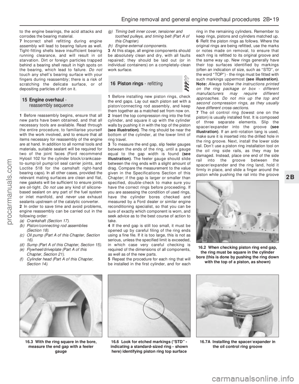
2Insert the top compression ring into the first
cylinder, and square it up with the cylinder
walls by pushing it in with the top of the piston
(see illustration). The ring should be near the
bottom of the cylinder, at the lower limit of
ring travel.
3To measure the end gap, slip feeler gauges
between the ends of the ring, until a gauge
equal to the gap width is found (see
illustration). The feeler gauge should slide
between the ring ends with a slight amount of
drag. Compare the measurement to the value
given in the Specifications Section of this
Chapter; if the gap is larger or smaller than
specified, double-check to make sure you
have the correct rings before proceeding. If
you are assessing the condition of used rings,
have the cylinder bores checked and
measured by a Ford dealer or similar engine
reconditioning specialist, so that you can be
sure of exactly which component is worn, and
seek advice as to the best course of action to
take.
4If the end gap is still too small, it must be
opened up by careful filing of the ring ends
using a fine file. If it is too large, this is not as
serious, unless the specified limit is exceeded,
in which case very careful checking is
required of the dimensions of all components,
as well as of the new parts.
5Repeat the procedure for each ring that will
be installed in the first cylinder, and for eachring in the remaining cylinders. Remember to
keep rings, pistons and cylinders matched up.
6Refit the piston rings as follows. Where the
original rings are being refitted, use the marks
or notes made on removal, to ensure that
each ring is refitted to its original groove and
the same way up. New rings generally have
their top surfaces identified by markings
(often an indication of size, such as “STD”, or
the word “TOP”) - the rings must be fitted with
such markings uppermost (see illustration).
Note:Always follow the instructions printed
on the ring package or box - different
manufacturers may require different
approaches. Do not mix up the top and
second compression rings, as they usually
have different cross-sections.
7The oil control ring (lowest one on the
piston) is usually installed first. It is composed
of three separate elements. Slip the
spacer/expander into the groove (see
illustration). If an anti-rotation tang is used,
make sure it is inserted into the drilled hole in
the ring groove. Next, install the lower side
rail. Don’t use a piston ring installation tool on
the oil ring side rails, as they may be
damaged. Instead, place one end of the side
rail into the groove between the
spacer/expander and the ring land, hold it
firmly in place, and slide a finger around the
piston while pushing the rail into the groove
16 Piston rings - refitting
15 Engine overhaul -
reassembly sequence
Engine removal and general engine overhaul procedures 2B•19
2B
16.7A Installing the spacer/expander in
the oil control ring groove
16.2 When checking piston ring end gap,
the ring must be square in the cylinder
bore (this is done by pushing the ring down
with the top of a piston, as shown)
16.3 With the ring square in the bore,
measure the end gap with a feeler
gauge16.6 Look for etched markings (“STD” -
indicating a standard-sized ring - shown
here) identifying piston ring top surface
procarmanuals.com
Page 87 of 279
make sure that no dirt or oil was between the
bearing shells and the caps or block when the
clearance was measured. If the Plastigage is
noticeably wider at one end than the other,
the journal may be tapered (see Section 13).
12Carefully scrape all traces of the
Plastigage material off the main bearing
journals and the bearing surfaces. Be very
careful not to scratch the bearing - use your
fingernail or the edge of a credit card.
Final refitting
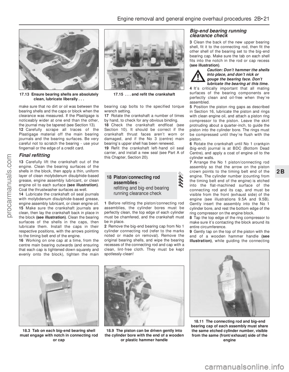
13Carefully lift the crankshaft out of the
engine. Clean the bearing surfaces of the
shells in the block, then apply a thin, uniform
layer of clean molybdenum disulphide-based
grease, engine assembly lubricant, or clean
engine oil to each surface (see illustration).
Coat the thrustwasher surfaces as well.
14Lubricate the crankshaft oil seal journals
with molybdenum disulphide-based grease,
engine assembly lubricant, or clean engine oil.
15Make sure the crankshaft journals are
clean, then lay the crankshaft back in place in
the block (see illustration). Clean the bearing
surfaces of the shells in the caps, then
lubricate them. Install the caps in their
respective positions, with the arrows pointing
to the timing belt end of the engine.
16Working on one cap at a time, from the
centre main bearing outwards (and ensuring
that each cap is tightened down squarely and
evenly onto the block), tighten the mainbearing cap bolts to the specified torque
wrench setting.
17Rotate the crankshaft a number of times
by hand, to check for any obvious binding.
18Check the crankshaft endfloat (see
Section 10). It should be correct if the
crankshaft thrust faces aren’t worn or
damaged, and if the No 3 (centre) main
bearing’s upper shell has been renewed.
19Refit the crankshaft left-hand oil seal
carrier, and install a new seal (see Part A of
this Chapter, Section 20).
1Before refitting the piston/connecting rod
assemblies, the cylinder bores must be
perfectly clean, the top edge of each cylinder
must be chamfered, and the crankshaft must
be in place.
2Remove the big-end bearing cap from No 1
cylinder connecting rod (refer to the marks
noted or made on removal). Remove the
original bearing shells, and wipe the bearing
recesses of the connecting rod and cap with a
clean, lint-free cloth. They must be kept
spotlessly-clean!
Big-end bearing running
clearance check
3Clean the back of the new upper bearing
shell, fit it to the connecting rod, then fit the
other shell of the bearing set to the big-end
bearing cap. Make sure the tab on each shell
fits into the notch in the rod or cap recess
(see illustration).
Caution: Don’t hammer the shells
into place, and don’t nick or
gouge the bearing face. Don’t
lubricate the bearing at this time.
4It’s critically important that all mating
surfaces of the bearing components are
perfectly clean and oil-free when they’re
assembled.
5Position the piston ring gaps as described
in Section 16, lubricate the piston and rings
with clean engine oil, and attach a piston ring
compressor to the piston. Leave the skirt
protruding about a quarter-inch, to guide the
piston into the cylinder bore. The rings must
be compressed until they’re flush with the
piston.
6Rotate the crankshaft until No 1 crankpin
(big-end) journal is at BDC (Bottom Dead
Centre), and apply a coat of engine oil to the
cylinder walls.
7Arrange the No 1 piston/connecting rod
assembly so that the arrow on the piston
crown points to the timing belt end of the
engine. The cylinder number (counting from
the timing belt end of the engine) is etched
into the flat-machined surface of the
connecting rod and its cap, and must be
visible from the front (exhaust side) of the
engine (see illustrations 9.5A and 9.5B).
Gently insert the assembly into the No 1
cylinder bore, and rest the bottom edge of the
ring compressor on the engine block.
8Tap the top edge of the ring compressor to
make sure it’s contacting the block around its
entire circumference.
9Gently tap on the top of the piston with the
end of a wooden hammer handle (see
illustration), while guiding the connecting
18 Piston/connecting rod
assemblies-
refitting and big-end bearing
running clearance check
Engine removal and general engine overhaul procedures 2B•21
2B
18.3 Tab on each big-end bearing shell
must engage with notch in connecting rod
or cap18.9 The piston can be driven gently into
the cylinder bore with the end of a wooden
or plastic hammer handle
18.11 The connecting rod and big-end
bearing cap of each assembly must share
the same etched cylinder number, visible
from the same (front/exhaust) side of the
engine
17.13 Ensure bearing shells are absolutely
clean, lubricate liberally . . .17.15 . . . and refit the crankshaft
procarmanuals.com
Page 162 of 279
spring must now be carefully released from
the compressor. If it is to be re-used, the
spring can be left in compression.
7With the strut assembly now completely
dismantled, examine all the components for
wear and damage, and check the bearing for
smoothness of operation. Renew components
as necessary.
8Examine the strut for signs of fluid leakage.
Check the strut piston for signs of pitting
along its entire length, and check the strut
body for signs of damage. Test the operation
of the strut, while holding it in an upright
position, by moving the piston through a full
stroke, and then through short strokes of 50
to 100 mm. In both cases, the resistance felt
should be smooth and continuous. If the
resistance is jerky, uneven, or if there is any
visible sign of wear or damage to the strut,
renewal is necessary.
9Reassembly is a reversal of dismantling,
noting the following points:
(a) Make sure that the coil spring ends are
correctly located in the upper and lower
seats before releasing the compressor.
(b) Check that the bearing is correctly fitted
to the piston rod seat.
(c) Tighten the thrust bearing retaining nut to
the specified torque.
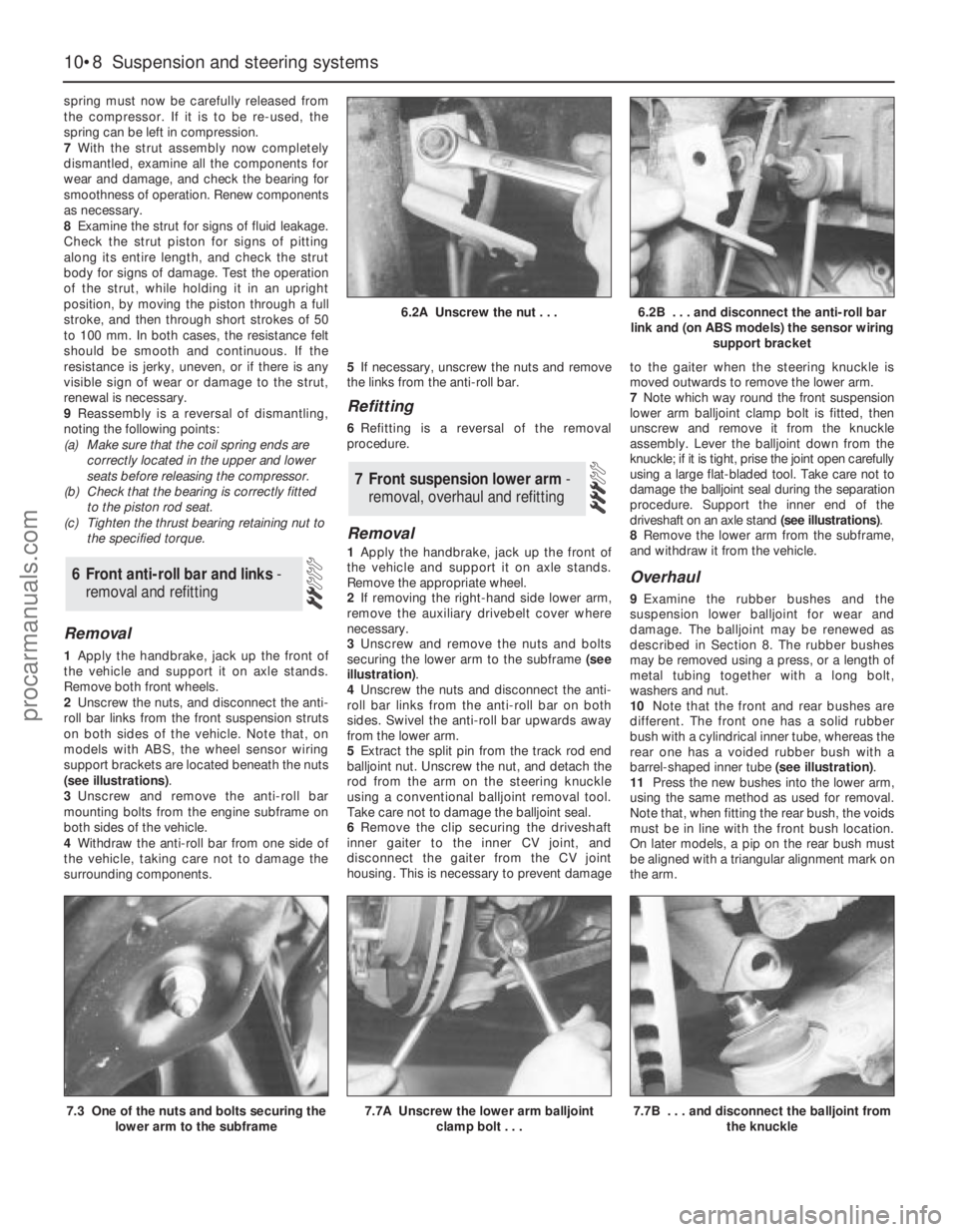
Removal
1Apply the handbrake, jack up the front of
the vehicle and support it on axle stands.
Remove both front wheels.
2Unscrew the nuts, and disconnect the anti-
roll bar links from the front suspension struts
on both sides of the vehicle. Note that, on
models with ABS, the wheel sensor wiring
support brackets are located beneath the nuts
(see illustrations).
3Unscrew and remove the anti-roll bar
mounting bolts from the engine subframe on
both sides of the vehicle.
4Withdraw the anti-roll bar from one side of
the vehicle, taking care not to damage the
surrounding components.5If necessary, unscrew the nuts and remove
the links from the anti-roll bar.
Refitting
6Refitting is a reversal of the removal
procedure.
Removal
1Apply the handbrake, jack up the front of
the vehicle and support it on axle stands.
Remove the appropriate wheel.
2If removing the right-hand side lower arm,
remove the auxiliary drivebelt cover where
necessary.
3Unscrew and remove the nuts and bolts
securing the lower arm to the subframe (see
illustration).
4Unscrew the nuts and disconnect the anti-
roll bar links from the anti-roll bar on both
sides. Swivel the anti-roll bar upwards away
from the lower arm.
5Extract the split pin from the track rod end
balljoint nut. Unscrew the nut, and detach the
rod from the arm on the steering knuckle
using a conventional balljoint removal tool.
Take care not to damage the balljoint seal.
6Remove the clip securing the driveshaft
inner gaiter to the inner CV joint, and
disconnect the gaiter from the CV joint
housing. This is necessary to prevent damageto the gaiter when the steering knuckle is
moved outwards to remove the lower arm.
7Note which way round the front suspension
lower arm balljoint clamp bolt is fitted, then
unscrew and remove it from the knuckle
assembly. Lever the balljoint down from the
knuckle; if it is tight, prise the joint open carefully
using a large flat-bladed tool. Take care not to
damage the balljoint seal during the separation
procedure. Support the inner end of the
driveshaft on an axle stand (see illustrations).
8Remove the lower arm from the subframe,
and withdraw it from the vehicle.
Overhaul
9Examine the rubber bushes and the
suspension lower balljoint for wear and
damage. The balljoint may be renewed as
described in Section 8. The rubber bushes
may be removed using a press, or a length of
metal tubing together with a long bolt,
washers and nut.
10Note that the front and rear bushes are
different. The front one has a solid rubber
bush with a cylindrical inner tube, whereas the
rear one has a voided rubber bush with a
barrel-shaped inner tube (see illustration).
11Press the new bushes into the lower arm,
using the same method as used for removal.
Note that, when fitting the rear bush, the voids
must be in line with the front bush location.
On later models, a pip on the rear bush must
be aligned with a triangular alignment mark on
the arm.
7 Front suspension lower arm -
removal, overhaul and refitting
6 Front anti-roll bar and links -
removal and refitting
10•8 Suspension and steering systems
6.2A Unscrew the nut . . .6.2B . . . and disconnect the anti-roll bar
link and (on ABS models) the sensor wiring
support bracket
7.3 One of the nuts and bolts securing the
lower arm to the subframe7.7A Unscrew the lower arm balljoint
clamp bolt . . .7.7B . . . and disconnect the balljoint from
the knuckle
procarmanuals.com