1993 FORD MONDEO height
[x] Cancel search: heightPage 6 of 279
0•6General Dimensions & Weights
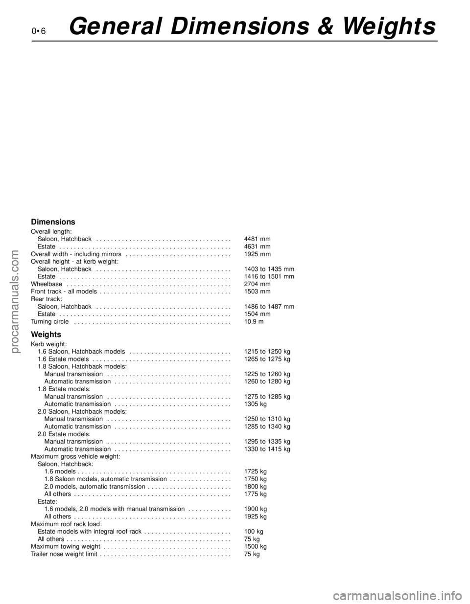
Dimensions
Overall length:
Saloon, Hatchback . . . . . . . . . . . . . . . . . . . . . . . . . . . . . . . . . . . . . 4481 mm
Estate . . . . . . . . . . . . . . . . . . . . . . . . . . . . . . . . . . . . . . . . . . . . . . . 4631 mm
Overall width - including mirrors . . . . . . . . . . . . . . . . . . . . . . . . . . . . . 1925 mm
Overall height - at kerb weight:
Saloon, Hatchback . . . . . . . . . . . . . . . . . . . . . . . . . . . . . . . . . . . . . 1403 to 1435 mm
Estate . . . . . . . . . . . . . . . . . . . . . . . . . . . . . . . . . . . . . . . . . . . . . . . 1416 to 1501 mm
Wheelbase . . . . . . . . . . . . . . . . . . . . . . . . . . . . . . . . . . . . . . . . . . . . . 2704 mm
Front track - all models . . . . . . . . . . . . . . . . . . . . . . . . . . . . . . . . . . . . 1503 mm
Rear track:
Saloon, Hatchback . . . . . . . . . . . . . . . . . . . . . . . . . . . . . . . . . . . . . 1486 to 1487 mm
Estate . . . . . . . . . . . . . . . . . . . . . . . . . . . . . . . . . . . . . . . . . . . . . . . 1504 mm
Turning circle . . . . . . . . . . . . . . . . . . . . . . . . . . . . . . . . . . . . . . . . . . . 10.9 m
Weights
Kerb weight:
1.6 Saloon, Hatchback models . . . . . . . . . . . . . . . . . . . . . . . . . . . . 1215 to 1250 kg
1.6 Estate models . . . . . . . . . . . . . . . . . . . . . . . . . . . . . . . . . . . . . . 1265 to 1275 kg
1.8 Saloon, Hatchback models:
Manual transmission . . . . . . . . . . . . . . . . . . . . . . . . . . . . . . . . . . 1225 to 1260 kg
Automatic transmission . . . . . . . . . . . . . . . . . . . . . . . . . . . . . . . . 1260 to 1280 kg
1.8 Estate models:
Manual transmission . . . . . . . . . . . . . . . . . . . . . . . . . . . . . . . . . . 1275 to 1285 kg
Automatic transmission . . . . . . . . . . . . . . . . . . . . . . . . . . . . . . . . 1305 kg
2.0 Saloon, Hatchback models:
Manual transmission . . . . . . . . . . . . . . . . . . . . . . . . . . . . . . . . . . 1250 to 1310 kg
Automatic transmission . . . . . . . . . . . . . . . . . . . . . . . . . . . . . . . . 1285 to 1340 kg
2.0 Estate models:
Manual transmission . . . . . . . . . . . . . . . . . . . . . . . . . . . . . . . . . . 1295 to 1335 kg
Automatic transmission . . . . . . . . . . . . . . . . . . . . . . . . . . . . . . . . 1330 to 1415 kg
Maximum gross vehicle weight:
Saloon, Hatchback:
1.6 models . . . . . . . . . . . . . . . . . . . . . . . . . . . . . . . . . . . . . . . . . . 1725 kg
1.8 Saloon models, automatic transmission . . . . . . . . . . . . . . . . . 1750 kg
2.0 models, automatic transmission . . . . . . . . . . . . . . . . . . . . . . . 1800 kg
All others . . . . . . . . . . . . . . . . . . . . . . . . . . . . . . . . . . . . . . . . . . . 1775 kg
Estate:
1.6 models, 2.0 models with manual transmission . . . . . . . . . . . . 1900 kg
All others . . . . . . . . . . . . . . . . . . . . . . . . . . . . . . . . . . . . . . . . . . . 1925 kg
Maximum roof rack load:
Estate models with integral roof rack . . . . . . . . . . . . . . . . . . . . . . . . 100 kg
All others . . . . . . . . . . . . . . . . . . . . . . . . . . . . . . . . . . . . . . . . . . . . . 75 kg
Maximum towing weight . . . . . . . . . . . . . . . . . . . . . . . . . . . . . . . . . . . 1500 kg
Trailer nose weight limit . . . . . . . . . . . . . . . . . . . . . . . . . . . . . . . . . . . . 75 kg
procarmanuals.com
Page 8 of 279
Seat belts and seats
Note: The following checks are applicable to
all seat belts, front and rear.
MExamine the webbing of all the belts
(including rear belts if fitted) for cuts, serious
fraying or deterioration. Fasten and unfasten
each belt to check the buckles. If applicable,
check the retracting mechanism. Check the
security of all seat belt mountings accessible
from inside the vehicle.
MThe front seats themselves must be
securely attached and the backrests must
lock in the upright position.
Doors
MBoth front doors must be able to be opened
and closed from outside and inside, and must
latch securely when closed.
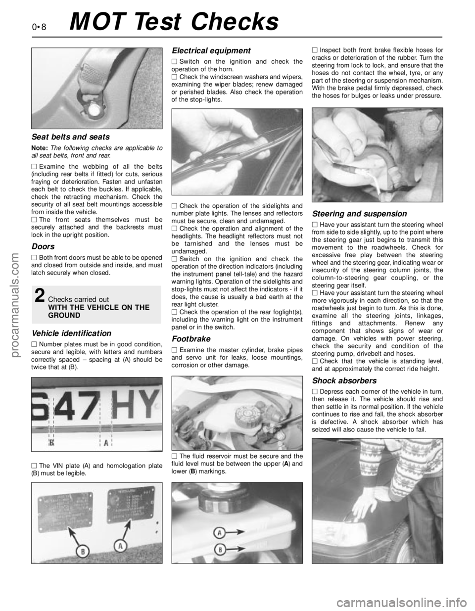
Vehicle identification
MNumber plates must be in good condition,
secure and legible, with letters and numbers
correctly spaced – spacing at (A) should be
twice that at (B).
MThe VIN plate (A) and homologation plate
(B) must be legible.
Electrical equipment
MSwitch on the ignition and check the
operation of the horn.
MCheck the windscreen washers and wipers,
examining the wiper blades; renew damaged
or perished blades. Also check the operation
of the stop-lights.
MCheck the operation of the sidelights and
number plate lights. The lenses and reflectors
must be secure, clean and undamaged.
MCheck the operation and alignment of the
headlights. The headlight reflectors must not
be tarnished and the lenses must be
undamaged.
MSwitch on the ignition and check the
operation of the direction indicators (including
the instrument panel tell-tale) and the hazard
warning lights. Operation of the sidelights and
stop-lights must not affect the indicators - if it
does, the cause is usually a bad earth at the
rear light cluster.
MCheck the operation of the rear foglight(s),
including the warning light on the instrument
panel or in the switch.
Footbrake
MExamine the master cylinder, brake pipes
and servo unit for leaks, loose mountings,
corrosion or other damage.
MThe fluid reservoir must be secure and the
fluid level must be between the upper (A) and
lower (B) markings.MInspect both front brake flexible hoses for
cracks or deterioration of the rubber. Turn the
steering from lock to lock, and ensure that the
hoses do not contact the wheel, tyre, or any
part of the steering or suspension mechanism.
With the brake pedal firmly depressed, check
the hoses for bulges or leaks under pressure.
Steering and suspension
MHave your assistant turn the steering wheel
from side to side slightly, up to the point where
the steering gear just begins to transmit this
movement to the roadwheels. Check for
excessive free play between the steering
wheel and the steering gear, indicating wear or
insecurity of the steering column joints, the
column-to-steering gear coupling, or the
steering gear itself.
MHave your assistant turn the steering wheel
more vigorously in each direction, so that the
roadwheels just begin to turn. As this is done,
examine all the steering joints, linkages,
fittings and attachments. Renew any
component that shows signs of wear or
damage. On vehicles with power steering,
check the security and condition of the
steering pump, drivebelt and hoses.
MCheck that the vehicle is standing level,
and at approximately the correct ride height.
Shock absorbers
MDepress each corner of the vehicle in turn,
then release it. The vehicle should rise and
then settle in its normal position. If the vehicle
continues to rise and fall, the shock absorber
is defective. A shock absorber which has
seized will also cause the vehicle to fail.
2Checks carried out
WITH THE VEHICLE ON THE
GROUND
0•8MOT Test Checks
procarmanuals.com
Page 73 of 279
31Where the vehicle is fitted with manual
transmission, disconnect the driveshafts from
the transmission as follows, referring to
Chapter 8 for further details when required:
(a) Unscrew the nuts securing the right-hand
driveshaft support bearing, and withdraw
the heat shield.
(b) Pull the right-hand driveshaft out of the
transmission; be prepared to catch any
spilt oil.
(c) Secure the driveshaft clear of the
engine/transmission - remember that the
unit is to be lowered out of the vehicle -
and ensure that the inner joint is not
turned through more than 18°.
(d) Prise the left-hand driveshaft out of the
transmission - again, be prepared for oil
spillage. Secure the driveshaft clear of the
engine/transmission, and ensure that its
inner joint is not turned through more than
18°.
32Where the vehicle is fitted with automatic
transmission, proceed as follows, referring to
Chapter 7, Part B and to Chapter 8 for further
details when required:
(a) Unscrew its centre bolt, then unbolt the
engine/transmission rear mounting
bracket from the transmission.
(b) Disconnect the fluid cooler pipe from the
rear of the transmission, and secure it
clear of the unit.
(c) Prise the left-hand driveshaft out of the
transmission; be prepared to catch any
spilt oil.
(d) Secure the driveshaft clear of the
engine/transmission - remember that the
unit is to be lowered out of the vehicle -
and ensure that the inner joint is not
turned through more than 18°.
(e) Unscrew the nuts securing the right-hand
driveshaft support bearing, and withdraw
the heat shield.
(f) Pull the right-hand driveshaft out of the
transmission - again, be prepared for oil
spillage. Secure the driveshaft clear of the
engine/transmission, and ensure that its
inner joint is not turned through more than
18°.
(g) Disconnect the fluid cooler pipe from the
front of the transmission, and secure it
clear of the unit.
33The engine/transmission unit should now
be hanging on the right- and left-hand
mountings only, with all components which
connect it to the rest of the vehicle
disconnected or removed and secured well
clear of the unit. Make a final check that this is
the case, then ensure that the body is
securely supported, high enough to permit the
withdrawal of the engine/transmission unit
from underneath; allow for the height of the
engine dolly, if used.
34Take the weight of the engine/
transmission unit, using the lifting eyes
provided on the cylinder head. Unscrew the
six nuts securing the right-hand mounting
bracket, then the three nuts securing the left-
hand bracket. Warning: Do not put any part of
your body under the vehicle, or
under the engine/transmission
unit, when they are supported only by a
hoist or other lifting equipment.
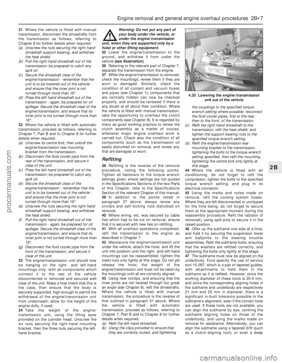
35Lower the engine/transmission to the
ground, and withdraw it from under the
vehicle (see illustration).
36Referring to the relevant part of Chapter 7,
separate the transmission from the engine.
37While the engine/transmission is removed,
check the mountings; renew them if they are
worn or damaged. Similarly, check the
condition of all coolant and vacuum hoses
and pipes (see Chapter 1); components that
are normally hidden can now be checked
properly, and should be renewed if there is
any doubt at all about their condition. Where
the vehicle is fitted with manual transmission,
take the opportunity to overhaul the clutch
components (see Chapter 8). It is regarded by
many as good working practice to renew the
clutch assembly as a matter of course,
whenever major engine overhaul work is
carried out. Check also the condition of all
components (such as the transmission oil
seals) disturbed on removal, and renew any
that are damaged or worn.
Refitting
38Refitting is the reverse of the removal
procedure, noting the following points.
Tighten all fasteners to the torque wrench
settings given; where settings are not quoted
in the Specifications Sections of the two Parts
of this Chapter, refer to the Specifications
Section of the relevant Chapter of this manual.
39In addition to the points noted in
paragraph 37 above, always renew any
circlips and self-locking nuts disturbed on
removal.
40Where wiring, etc, was secured by cable
ties which had to be cut on removal, ensure
that it is secured with new ties on refitting.
41With all overhaul operations completed,
refit the transmission to the engine as
described in Chapter 7.
42Manoeuvre the engine/transmission unit
under the vehicle, attach the hoist, and lift the
unit into position until the right- and left-hand
mountings can be reassembled; tighten the
(new) nuts only lightly at this stage. Do not yet
release the hoist; the weight of the
engine/transmission unit must not be taken by
the mountings until all are correctly aligned.
43Using new circlips, and ensuring that the
inner joints are not twisted through too great
an angle (see Chapter 8), refit the driveshafts.
Where the vehicle is fitted with manual
transmission, the procedure is the reverse of
that outlined in paragraph 31 above. Where
the vehicle is fitted with automatic
transmission, proceed as follows, referring to
Chapter 7, Part B and to Chapter 8 for further
details when required:
(a) Refit the left-hand driveshaft.
(b) Using the clips provided to ensure that
they are correctly routed, and tighteningthe couplings to the specified torque
wrench setting where possible, reconnect
the fluid cooler pipes, first to the rear,
then to the front, of the transmission.
(c) Refit the right-hand driveshaft to the
transmission, refit the heat shield, and
tighten the support bearing nuts to the
specified torque wrench setting.
(d) Refit the engine/transmission rear
mounting bracket to the transmission,
tightening the bolts to the torque wrench
setting specified, then refit the mounting,
tightening the centre bolt only lightly at
this stage.
44Where the vehicle is fitted with air
conditioning, do not forget to refit the
compressor; tighten the bolts to the specified
torque wrench setting, and plug in its
electrical connector.
45Using the marks and notes made on
removal, refit the cooling system hoses.
Where they are left disconnected or unclipped
for the time being, do not forget to secure
them at the appropriate moment during the
reassembly procedure. Refit the radiator (if
removed), using split pins to secure it in the
raised position.
46Offer up the subframe one side at a time,
and hold it by securing the suspension lower
arm balljoints to the steering knuckle
assemblies. Refit the subframe bolts, ensuring
that the washers are refitted correctly, and
tightening the bolts only lightly at this stage.
47The subframe must now be aligned on the
underbody. Ford specify the use of service
tool 15-097, which is a pair of tapered guides,
with attachments to hold them in the
subframe as it is refitted. However, since the
working diameter of these tools is 20.4 mm,
and since the corresponding aligning holes in
the subframe and underbody are respectively
21 mm and 22 mm in diameter, there is a
significant in-built tolerance possible in the
subframe’s alignment, even if the correct tools
are used. If these tools are not available, you
can align the subframe by eye, centring the
subframe aligning holes on those of the
underbody, and using the marks made on
removal for assistance. Alternatively, you can
align the subframe using a tapered drift (such
as a clutch-aligning tool), or even a deep
Engine removal and general engine overhaul procedures 2B•7
2B
4.35 Lowering the engine/transmission
unit out of the vehicle
procarmanuals.com
Page 78 of 279
grinding or head resurfacing. Use
compressed air, if available, to blow out all the
oil holes and passages.
2Beginning at one end of the head, lubricate
and install the first valve. Apply molybdenum
disulphide-based grease or clean engine oil to
the valve stem, and refit the valve. Where the
original valves are being re-used, ensure that
each is refitted in its original guide. If new
valves are being fitted, insert them into the
locations to which they have been ground.
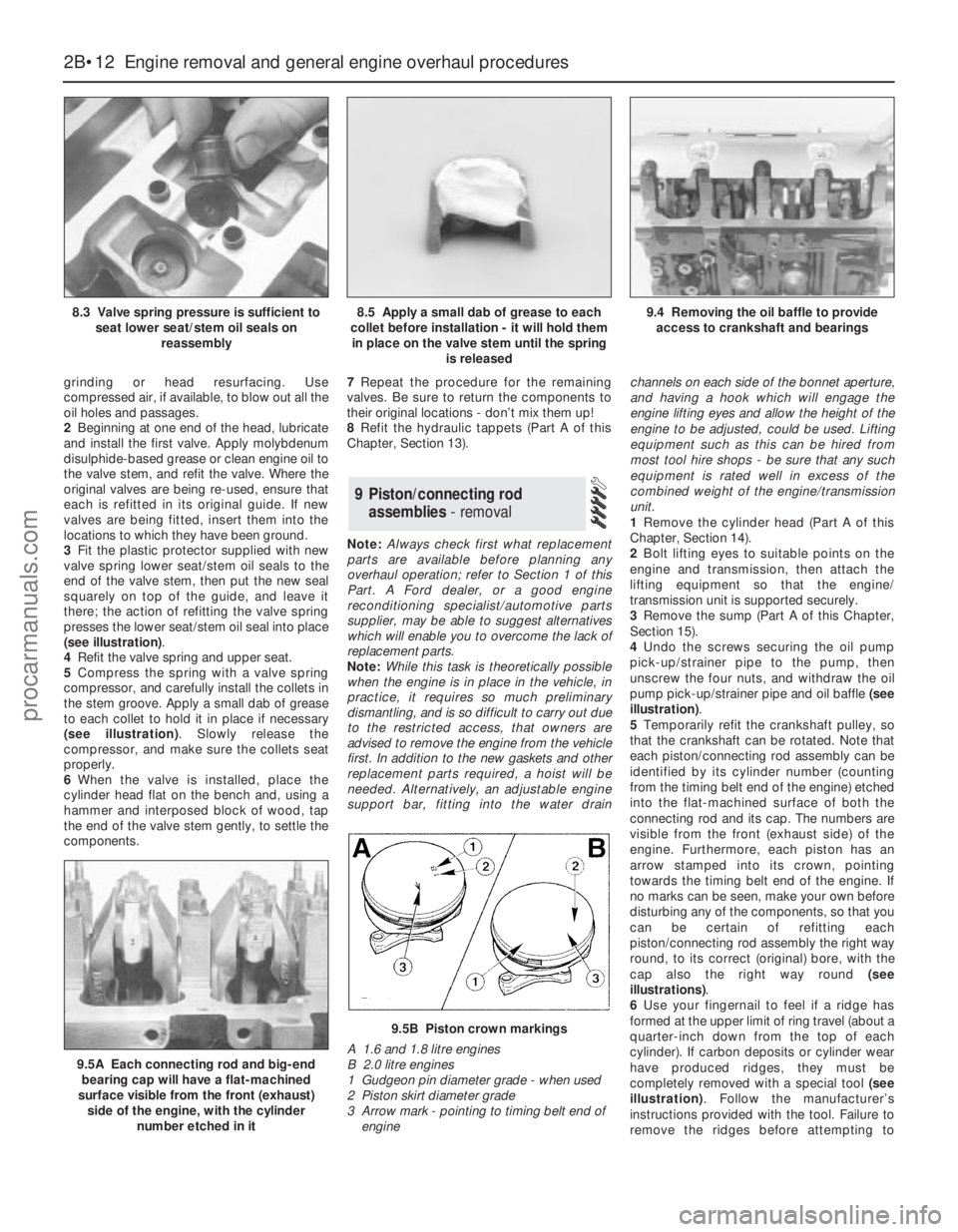
3Fit the plastic protector supplied with new
valve spring lower seat/stem oil seals to the
end of the valve stem, then put the new seal
squarely on top of the guide, and leave it
there; the action of refitting the valve spring
presses the lower seat/stem oil seal into place
(see illustration).
4Refit the valve spring and upper seat.
5Compress the spring with a valve spring
compressor, and carefully install the collets in
the stem groove. Apply a small dab of grease
to each collet to hold it in place if necessary
(see illustration). Slowly release the
compressor, and make sure the collets seat
properly.
6When the valve is installed, place the
cylinder head flat on the bench and, using a
hammer and interposed block of wood, tap
the end of the valve stem gently, to settle the
components.7Repeat the procedure for the remaining
valves. Be sure to return the components to
their original locations - don’t mix them up!
8Refit the hydraulic tappets (Part A of this
Chapter, Section 13).
Note:Always check first what replacement
parts are available before planning any
overhaul operation; refer to Section 1 of this
Part. A Ford dealer, or a good engine
reconditioning specialist/automotive parts
supplier, may be able to suggest alternatives
which will enable you to overcome the lack of
replacement parts.
Note:While this task is theoretically possible
when the engine is in place in the vehicle, in
practice, it requires so much preliminary
dismantling, and is so difficult to carry out due
to the restricted access, that owners are
advised to remove the engine from the vehicle
first. In addition to the new gaskets and other
replacement parts required, a hoist will be
needed. Alternatively, an adjustable engine
support bar, fitting into the water drainchannels on each side of the bonnet aperture,
and having a hook which will engage the
engine lifting eyes and allow the height of the
engine to be adjusted, could be used. Lifting
equipment such as this can be hired from
most tool hire shops - be sure that any such
equipment is rated well in excess of the
combined weight of the engine/transmission
unit.
1Remove the cylinder head (Part A of this
Chapter, Section 14).
2Bolt lifting eyes to suitable points on the
engine and transmission, then attach the
lifting equipment so that the engine/
transmission unit is supported securely.
3Remove the sump (Part A of this Chapter,
Section 15).
4Undo the screws securing the oil pump
pick-up/strainer pipe to the pump, then
unscrew the four nuts, and withdraw the oil
pump pick-up/strainer pipe and oil baffle (see
illustration).
5Temporarily refit the crankshaft pulley, so
that the crankshaft can be rotated. Note that
each piston/connecting rod assembly can be
identified by its cylinder number (counting
from the timing belt end of the engine) etched
into the flat-machined surface of both the
connecting rod and its cap. The numbers are
visible from the front (exhaust side) of the
engine. Furthermore, each piston has an
arrow stamped into its crown, pointing
towards the timing belt end of the engine. If
no marks can be seen, make your own before
disturbing any of the components, so that you
can be certain of refitting each
piston/connecting rod assembly the right way
round, to its correct (original) bore, with the
cap also the right way round (see
illustrations).
6Use your fingernail to feel if a ridge has
formed at the upper limit of ring travel (about a
quarter-inch down from the top of each
cylinder). If carbon deposits or cylinder wear
have produced ridges, they must be
completely removed with a special tool (see
illustration). Follow the manufacturer’s
instructions provided with the tool. Failure to
remove the ridges before attempting to
9 Piston/connecting rod
assemblies- removal
2B•12 Engine removal and general engine overhaul procedures
8.3 Valve spring pressure is sufficient to
seat lower seat/stem oil seals on
reassembly8.5 Apply a small dab of grease to each
collet before installation - it will hold them
in place on the valve stem until the spring
is released9.4 Removing the oil baffle to provide
access to crankshaft and bearings
9.5A Each connecting rod and big-end
bearing cap will have a flat-machined
surface visible from the front (exhaust)
side of the engine, with the cylinder
number etched in it
9.5B Piston crown markings
A 1.6 and 1.8 litre engines
B 2.0 litre engines
1 Gudgeon pin diameter grade - when used
2 Piston skirt diameter grade
3 Arrow mark - pointing to timing belt end of
engine
procarmanuals.com
Page 173 of 279
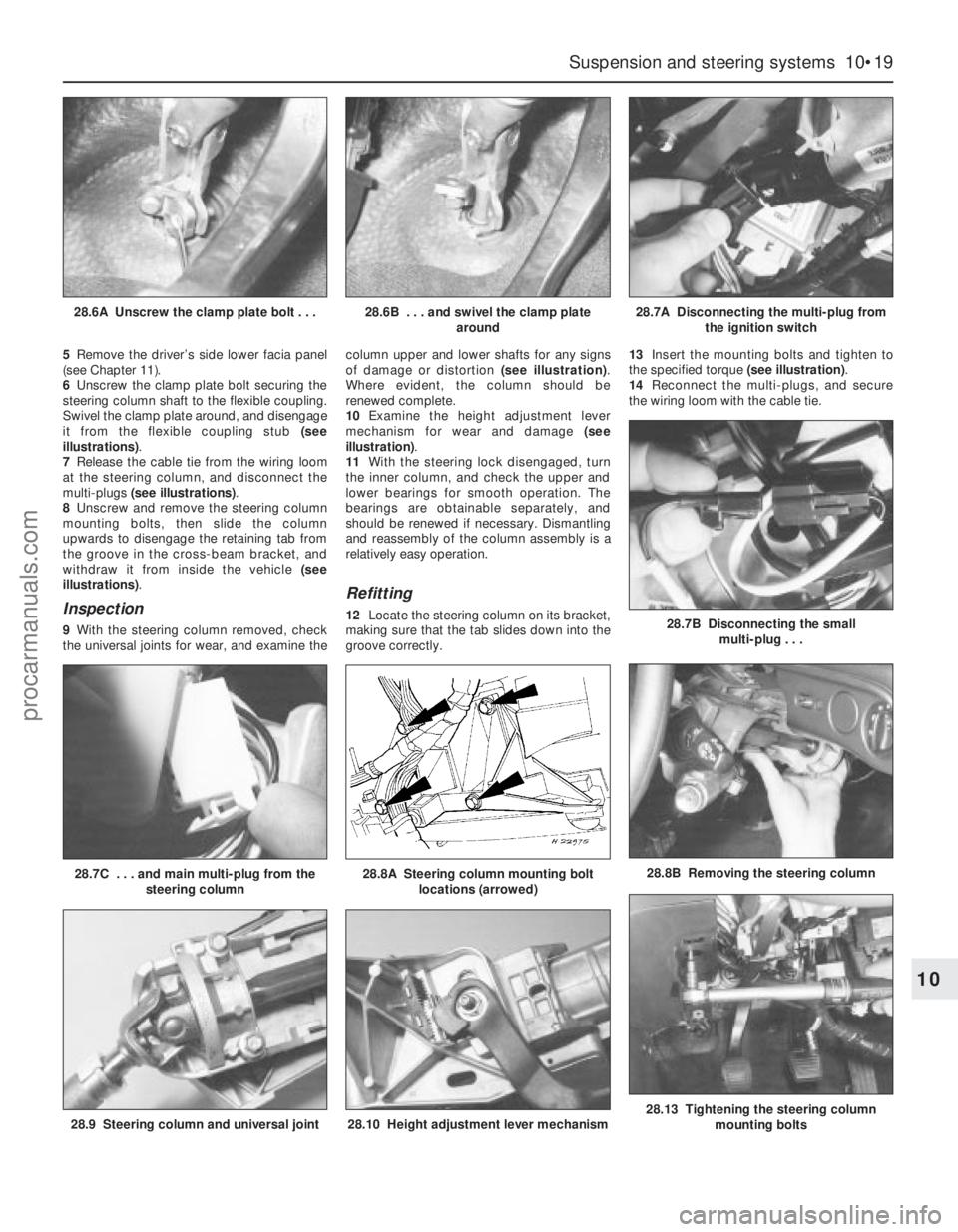
5Remove the driver’s side lower facia panel
(see Chapter 11).
6Unscrew the clamp plate bolt securing the
steering column shaft to the flexible coupling.
Swivel the clamp plate around, and disengage
it from the flexible coupling stub (see
illustrations).
7Release the cable tie from the wiring loom
at the steering column, and disconnect the
multi-plugs (see illustrations).
8Unscrew and remove the steering column
mounting bolts, then slide the column
upwards to disengage the retaining tab from
the groove in the cross-beam bracket, and
withdraw it from inside the vehicle (see
illustrations).
Inspection
9With the steering column removed, check
the universal joints for wear, and examine thecolumn upper and lower shafts for any signs
of damage or distortion (see illustration).
Where evident, the column should be
renewed complete.
10Examine the height adjustment lever
mechanism for wear and damage (see
illustration).
11With the steering lock disengaged, turn
the inner column, and check the upper and
lower bearings for smooth operation. The
bearings are obtainable separately, and
should be renewed if necessary. Dismantling
and reassembly of the column assembly is a
relatively easy operation.
Refitting
12Locate the steering column on its bracket,
making sure that the tab slides down into the
groove correctly.13Insert the mounting bolts and tighten to
the specified torque (see illustration).
14Reconnect the multi-plugs, and secure
the wiring loom with the cable tie.
Suspension and steering systems 10•19
10
28.9 Steering column and universal joint28.10 Height adjustment lever mechanism28.13 Tightening the steering column
mounting bolts
28.7C . . . and main multi-plug from the
steering column28.8A Steering column mounting bolt
locations (arrowed)28.8B Removing the steering column
28.6A Unscrew the clamp plate bolt . . .28.6B . . . and swivel the clamp plate
around28.7A Disconnecting the multi-plug from
the ignition switch
28.7B Disconnecting the small
multi-plug . . .
procarmanuals.com
Page 176 of 279
3Start the engine, and allow it to run at a fast
idle. Check the hoses and connections for
leaks.
4Stop the engine, and recheck the fluid level.
Add more if necessary, up to the “MAX” or
“MAX COLD” mark.
5Start the engine again, allow it to idle, then
bleed the system by slowly turning the
steering wheel from side to side several times.
This should purge the system of all internal
air. However, if air remains in the system
(indicated by the steering operation being very
noisy), leave the vehicle overnight, and repeat
the procedure again the next day.
6If air still remains in the system, it may be
necessary to resort to the Ford method of
bleeding, which uses a vacuum pump. Turn
the steering to the right until it is near the stop,
then fit the vacuum pump to the fluid
reservoir, and apply 0.15 bars of vacuum.
Maintain the vacuum for a minimum of
5 minutes, then repeat the procedure with the
steering turned to the left.
7Keep the fluid level topped-up throughout
the bleeding procedure; note that, as the fluid
temperature increases, the level will rise.
8On completion, switch off the engine, and
return the front wheels to the straight-ahead
position.
Removal
1Disconnect the battery negative (earth) lead
(refer to Chapter 5, Section 1).
2Unscrew and remove the bolt securing the
hydraulic fluid line support to the engine lifting
bracket on the right-hand side of the engine.
3Unscrew and remove the bolt securing the
hydraulic fluid line support to the pump
mounting bracket.
4Position a suitable container beneath the
power steering pump, to catch spilt fluid.
5Loosen the clip, and disconnect the fluid
supply hose from the pump inlet. Plug the
hose, to prevent the ingress of dust and dirt.
6Unscrew the union nut, and disconnect the
high-pressure line from the pump. Allow the
fluid to drain into the container.
7Apply the handbrake, then jack up the front
of the vehicle and support it on axle stands.
Remove the right-hand front wheel.
8Unbolt and remove the lower drivebelt
cover.
9Using a spanner, rotate the drivebelt
tensioner in a clockwise direction to release
the belt tension, then slip the drivebelt off the
pulleys and remove from the vehicle. Refer to
Chapter 1 if necessary.
10Unscrew and remove the four mounting
bolts, and withdraw the power steering pump
from its bracket. Access to the bolts on the
right-hand side of the engine is gained by
turning the pump pulley until a hole lines up
with the bolt.
Refitting
11Locate the power steering pump on the
mounting bracket, and secure with the four
bolts. Tighten the bolts to the specified
torque.
12Slip the drivebelt over the pulleys, then
rotate the drivebelt tensioner in a clockwise
direction, and locate the drivebelt on it.
Release the tensioner to tension the drivebelt.
13Refit the lower belt cover.
14Refit the right-hand front wheel, and lower
the vehicle to the ground.
15If necessary, the sealing ring on the high-
pressure outlet should be renewed, using the
same procedure as described in Section 30,
paragraph 8.
16Reconnect the high-pressure line to the
pump, and tighten the union nut.
17Reconnect the fluid supply hose to the
pump inlet, and tighten the clip.
18Refit the hydraulic fluid line support to the
pump mounting bracket, and tighten the bolt.
19Refit the hydraulic fluid line support to the
engine lifting bracket on the right-hand side of
the engine, and tighten the bolt.
20Reconnect the battery negative lead.
21Bleed the power steering hydraulic
system as described in Section 33.
1Apply the handbrake, then jack up the front
of the vehicle and support it on axle stands.
Remove the appropriate front roadwheel.
2Using a suitable spanner, slacken the
locknut on the track rod by a quarter-turn.
Hold the track rod end stationary with another
spanner engaged with the special flats while
loosening the locknut.
3Extract the split pin, then unscrew and
remove the track rod end balljoint retaining
nut.
4To release the tapered shank of the balljoint
from the steering knuckle arm, use a balljoint
separator tool (if the balljoint is to be re-used,
take care not to damage the dust cover when
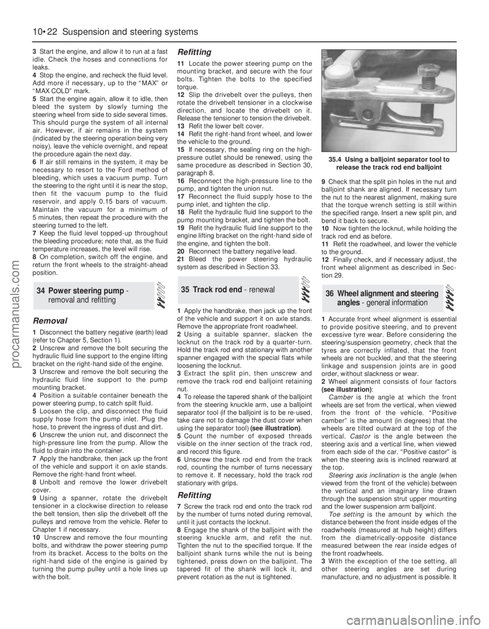
using the separator tool) (see illustration).
5Count the number of exposed threads
visible on the inner section of the track rod,
and record this figure.
6Unscrew the track rod end from the track
rod, counting the number of turns necessary
to remove it. If necessary, hold the track rod
stationary with grips.
Refitting
7Screw the track rod end onto the track rod
by the number of turns noted during removal,
until it just contacts the locknut.
8Engage the shank of the balljoint with the
steering knuckle arm, and refit the nut.
Tighten the nut to the specified torque. If the
balljoint shank turns while the nut is being
tightened, press down on the balljoint. The
tapered fit of the shank will lock it, and
prevent rotation as the nut is tightened.9Check that the split pin holes in the nut and
balljoint shank are aligned. If necessary turn
the nut to the nearest alignment, making sure
that the torque wrench setting is still within
the specified range. Insert a new split pin, and
bend it back to secure.
10Now tighten the locknut, while holding the
track rod end as before.
11Refit the roadwheel, and lower the vehicle
to the ground.
12Finally check, and if necessary adjust, the
front wheel alignment as described in Sec-
tion 29.
1Accurate front wheel alignment is essential
to provide positive steering, and to prevent
excessive tyre wear. Before considering the
steering/suspension geometry, check that the
tyres are correctly inflated, that the front
wheels are not buckled, and that the steering
linkage and suspension joints are in good
order, without slackness or wear.
2Wheel alignment consists of four factors
(see illustration):
Camberis the angle at which the front
wheels are set from the vertical, when viewed
from the front of the vehicle. “Positive
camber” is the amount (in degrees) that the
wheels are tilted outward at the top of the
vertical. Castoris the angle between the
steering axis and a vertical line, when viewed
from each side of the car. “Positive castor” is
when the steering axis is inclined rearward at
the top.
Steering axis inclinationis the angle (when
viewed from the front of the vehicle) between
the vertical and an imaginary line drawn
through the suspension strut upper mounting
and the lower suspension arm balljoint.
Toe settingis the amount by which the
distance between the front inside edges of the
roadwheels (measured at hub height) differs
from the diametrically-opposite distance
measured between the rear inside edges of
the front roadwheels.
3With the exception of the toe setting, all
other steering angles are set during
manufacture, and no adjustment is possible. It
36 Wheel alignment and steering
angles - general information35 Track rod end - renewal34 Power steering pump -
removal and refitting
10•22 Suspension and steering systems
35.4 Using a balljoint separator tool to
release the track rod end balljoint
procarmanuals.com
Page 183 of 279
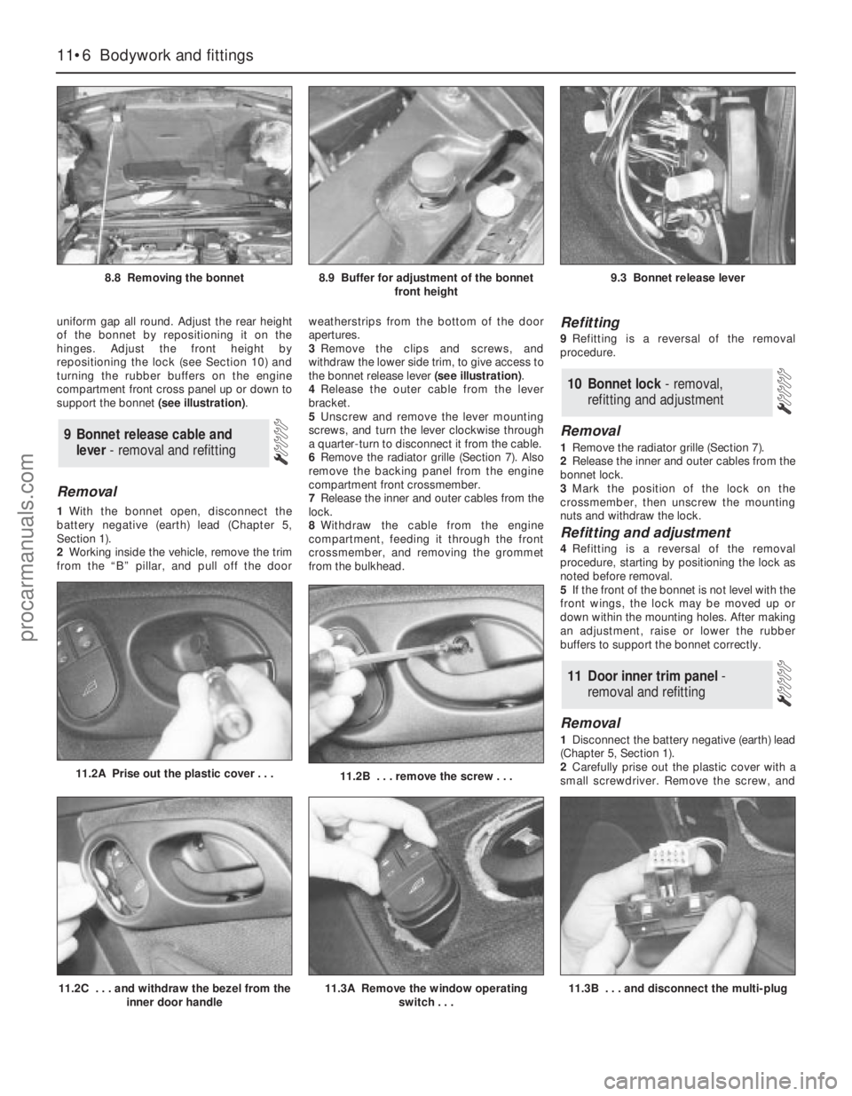
11.3B . . . and disconnect the multi-plug
uniform gap all round. Adjust the rear height
of the bonnet by repositioning it on the
hinges. Adjust the front height by
repositioning the lock (see Section 10) and
turning the rubber buffers on the engine
compartment front cross panel up or down to
support the bonnet (see illustration).
Removal
1With the bonnet open, disconnect the
battery negative (earth) lead (Chapter 5,
Section 1).
2Working inside the vehicle, remove the trim
from the “B” pillar, and pull off the doorweatherstrips from the bottom of the door
apertures.
3Remove the clips and screws, and
withdraw the lower side trim, to give access to
the bonnet release lever (see illustration).
4Release the outer cable from the lever
bracket.
5Unscrew and remove the lever mounting
screws, and turn the lever clockwise through
a quarter-turn to disconnect it from the cable.
6Remove the radiator grille (Section 7). Also
remove the backing panel from the engine
compartment front crossmember.
7Release the inner and outer cables from the
lock.
8Withdraw the cable from the engine
compartment, feeding it through the front
crossmember, and removing the grommet
from the bulkhead.
Refitting
9Refitting is a reversal of the removal
procedure.
Removal
1Remove the radiator grille (Section 7).
2Release the inner and outer cables from the
bonnet lock.
3Mark the position of the lock on the
crossmember, then unscrew the mounting
nuts and withdraw the lock.
Refitting and adjustment
4Refitting is a reversal of the removal
procedure, starting by positioning the lock as
noted before removal.
5If the front of the bonnet is not level with the
front wings, the lock may be moved up or
down within the mounting holes. After making
an adjustment, raise or lower the rubber
buffers to support the bonnet correctly.
Removal
1Disconnect the battery negative (earth) lead
(Chapter 5, Section 1).
2Carefully prise out the plastic cover with a
small screwdriver. Remove the screw, and
11 Door inner trim panel -
removal and refitting
10 Bonnet lock - removal,
refitting and adjustment
9 Bonnet release cable and
lever - removal and refitting
11•6 Bodywork and fittings
8.8 Removing the bonnet8.9 Buffer for adjustment of the bonnet
front height9.3 Bonnet release lever
11.2B . . . remove the screw . . .11.2A Prise out the plastic cover . . .
11.2C . . . and withdraw the bezel from the
inner door handle11.3A Remove the window operating
switch . . .
procarmanuals.com
Page 262 of 279
REF•3
MImpact screwdriver
MMicrometer and/or vernier calipers (see
illustrations)
MDial gauge (see illustration)
MUniversal electrical multi-meter
MCylinder compression gauge
(see illustration)
MClutch plate alignment set (see illustration)
MBrake shoe steady spring cup removal tool
(see illustration)
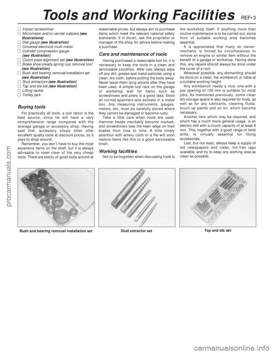
MBush and bearing removal/installation set
(see illustration)
MStud extractors (see illustration)
MTap and die set (see illustration)
MLifting tackle
MTrolley jack
Buying tools
For practically all tools, a tool factor is the
best source, since he will have a very
comprehensive range compared with the
average garage or accessory shop. Having
said that, accessory shops often offer
excellent quality tools at discount prices, so it
pays to shop around.
Remember, you don’t have to buy the most
expensive items on the shelf, but it is always
advisable to steer clear of the very cheap
tools. There are plenty of good tools around atreasonable prices, but always aim to purchase
items which meet the relevant national safety
standards. If in doubt, ask the proprietor or
manager of the shop for advice before making
a purchase.
Care and maintenance of tools
Having purchased a reasonable tool kit, it is
necessary to keep the tools in a clean and
serviceable condition. After use, always wipe
off any dirt, grease and metal particles using a
clean, dry cloth, before putting the tools away.
Never leave them lying around after they have
been used. A simple tool rack on the garage
or workshop wall for items such as
screwdrivers and pliers is a good idea. Store
all normal spanners and sockets in a metal
box. Any measuring instruments, gauges,
meters, etc, must be carefully stored where
they cannot be damaged or become rusty.
Take a little care when tools are used.
Hammer heads inevitably become marked,
and screwdrivers lose the keen edge on their
blades from time to time. A little timely
attention with emery cloth or a file will soon
restore items like this to a good serviceable
finish.
Working facilities
Not to be forgotten when discussing tools isthe workshop itself. If anything more than
routine maintenance is to be carried out, some
form of suitable working area becomes
essential.
It is appreciated that many an owner-
mechanic is forced by circumstances to
remove an engine or similar item without the
benefit of a garage or workshop. Having done
this, any repairs should always be done under
the cover of a roof.
Wherever possible, any dismantling should
be done on a clean, flat workbench or table at
a suitable working height.
Any workbench needs a vice; one with a
jaw opening of 100 mm is suitable for most
jobs. As mentioned previously, some clean
dry storage space is also required for tools, as
well as for any lubricants, cleaning fluids,
touch-up paints and so on, which become
necessary.
Another item which may be required, and
which has a much more general usage, is an
electric drill with a chuck capacity of at least 8
mm. This, together with a good range of twist
drills, is virtually essential for fitting
accessories.
Last, but not least, always keep a supply of
old newspapers and clean, lint-free rags
available, and try to keep any working area as
clean as possible.
Bush and bearing removal/installation setStud extractor setTap and die set
Tools and Working Facilities
procarmanuals.com