1993 FORD MONDEO steering tip
[x] Cancel search: steering tipPage 5 of 279

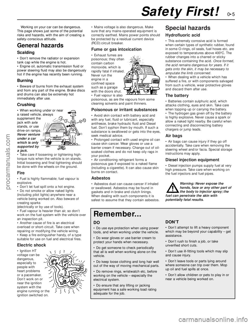
Working on your car can be dangerous.
This page shows just some of the potential
risks and hazards, with the aim of creating a
safety-conscious attitude.
General hazards
Scalding
• Don’t remove the radiator or expansion
tank cap while the engine is hot.
• Engine oil, automatic transmission fluid or
power steering fluid may also be dangerously
hot if the engine has recently been running.
Burning
• Beware of burns from the exhaust system
and from any part of the engine. Brake discs
and drums can also be extremely hot
immediately after use.
Crushing
• When working under or near
a raised vehicle, always
supplement the
jack with axle
stands, or use
drive-on ramps.
Never venture
under a car
which is only
supported by
a jack.
• Take care if loosening or tightening high-
torque nuts when the vehicle is on stands.
Initial loosening and final tightening should
be done with the wheels on the ground.
Fire
• Fuel is highly flammable; fuel vapour is
explosive.
• Don’t let fuel spill onto a hot engine.
• Do not smoke or allow naked lights
(including pilot lights) anywhere near a
vehicle being worked on. Also beware of
creating sparks
(electrically or by use of tools).
• Fuel vapour is heavier than air, so don’t
work on the fuel system with the vehicle over
an inspection pit.
• Another cause of fire is an electrical
overload or short-circuit. Take care when
repairing or modifying the vehicle wiring.
• Keep a fire extinguisher handy, of a type
suitable for use on fuel and electrical fires.
Electric shock
• Ignition HT
voltage can be
dangerous,
especially to
people with
heart problems
or a pacemaker.
Don’t work on or
near the ignition
system with the
engine running or the
ignition switched on.• Mains voltage is also dangerous. Make
sure that any mains-operated equipment is
correctly earthed. Mains power points should
be protected by a residual current device
(RCD) circuit breaker.
Fume or gas intoxication
• Exhaust fumes are
poisonous; they often
contain carbon
monoxide, which is
rapidly fatal if inhaled.
Never run the
engine in a
confined space
such as a garage
with the doors shut.
• Fuel vapour is also
poisonous, as are the vapours from some
cleaning solvents and paint thinners.
Poisonous or irritant substances
• Avoid skin contact with battery acid and
with any fuel, fluid or lubricant, especially
antifreeze, brake hydraulic fluid and Diesel
fuel. Don’t syphon them by mouth. If such a
substance is swallowed or gets into the eyes,
seek medical advice.
• Prolonged contact with used engine oil can
cause skin cancer. Wear gloves or use a
barrier cream if necessary. Change out of oil-
soaked clothes and do not keep oily rags in
your pocket.
• Air conditioning refrigerant forms a
poisonous gas if exposed to a naked flame
(including a cigarette). It can also cause skin
burns on contact.
Asbestos
• Asbestos dust can cause cancer if inhaled
or swallowed. Asbestos may be found in
gaskets and in brake and clutch linings.
When dealing with such components it is
safest to assume that they contain asbestos.
Special hazards
Hydrofluoric acid
• This extremely corrosive acid is formed
when certain types of synthetic rubber, found
in some O-rings, oil seals, fuel hoses etc, are
exposed to temperatures above 400
0C. The
rubber changes into a charred or sticky
substance containing the acid. Once formed,
the acid remains dangerous for years. If it
gets onto the skin, it may be necessary to
amputate the limb concerned.
• When dealing with a vehicle which has
suffered a fire, or with components salvaged
from such a vehicle, wear protective gloves
and discard them after use.
The battery
• Batteries contain sulphuric acid, which
attacks clothing, eyes and skin. Take care
when topping-up or carrying the battery.
• The hydrogen gas given off by the battery
is highly explosive. Never cause a spark or
allow a naked light nearby. Be careful when
connecting and disconnecting battery
chargers or jump leads.
Air bags
• Air bags can cause injury if they go off
accidentally. Take care when removing the
steering wheel and/or facia. Special storage
instructions may apply.
Diesel injection equipment
• Diesel injection pumps supply fuel at very
high pressure. Take care when working on
the fuel injectors and fuel pipes.
Warning: Never expose the
hands, face or any other part of
the body to injector spray; the
fuel can penetrate the skin with
potentially fatal results.
Remember...
DO
• Do use eye protection when using power
tools, and when working under the vehicle.
• Do wear gloves or use barrier cream to
protect your hands when necessary.
• Do get someone to check periodically
that all is well when working alone on the
vehicle.
• Do keep loose clothing and long hair well
out of the way of moving mechanical parts.
• Do remove rings, wristwatch etc, before
working on the vehicle – especially the
electrical system.
• Do ensure that any lifting or jacking
equipment has a safe working load rating
adequate for the job.
A few tips
DON’T
• Don’t attempt to lift a heavy component
which may be beyond your capability – get
assistance.
• Don’t rush to finish a job, or take
unverified short cuts.
• Don’t use ill-fitting tools which may slip
and cause injury.
• Don’t leave tools or parts lying around
where someone can trip over them. Mop
up oil and fuel spills at once.
• Don’t allow children or pets to play in or
near a vehicle being worked on.
0•5Safety First!
procarmanuals.com
Page 75 of 279

gear linkage heat shield. Reconnect the
gearchange linkage and transmission support
rods to the transmission, adjusting the linkage
using the marks made on removal (see
Chapter 7, Part A, for details).
56Re-install the remaining components and
fasteners in the reverse order of removal.
57Add coolant, engine oil and transmission
fluids as needed (see Chapter 1).
58Run the engine, and check for proper
operation and the absence of leaks. Shut off
the engine, and recheck the fluid levels.
59Remember that, since the front suspension
subframe and steering gear have been
disturbed, the wheel alignment and steering
angles must be checked fully and carefully as
soon as possible, with any necessary
adjustments being made. This operation is best
carried out by an experienced mechanic, using
proper checking equipment; the vehicle should
therefore be taken to a Ford dealer or similarly-
qualified person for attention.
1It is much easier to dismantle and work on
the engine if it is mounted on a portable engine
stand. These stands can often be hired from a
tool hire shop. Before the engine is mounted
on a stand, the flywheel/driveplate should be
removed (Part A of this Chapter, Section 21)
so that the stand bolts can be tightened into
the end of the cylinder block/crankcase.
2If a stand is not available, it is possible to
dismantle the engine with it mounted on
blocks, on a sturdy workbench or on the floor.
Be extra-careful not to tip or drop the engine
when working without a stand.
3If you are going to obtain a reconditioned
engine, all external components must be
removed first, to be transferred to the
replacement engine (just as they will if you are
doing a complete engine overhaul yourself).
Note:When removing the external
components from the engine, pay close
attention to details that may be helpful or
important during refitting. Note the fitted
position of gaskets, seals, spacers, pins,
washers, bolts and other small items.These
external components include the following:
(a) Alternator and brackets (Chapter 5).
(b) HT leads and spark plugs (Chapter 1).
(c) Thermostat and housing (Chapter 3).
(d) Dipstick tube.
(e) Fuel injection system components
(Chapter 4).
(f) All electrical switches and sensors - refer
to the appropriate Chapter.
(g) Inlet and exhaust manifolds (Part A of this
Chapter).
(h) Oil filter (Chapter 1).
(i) Engine/transmission mounting brackets
(Part A of this Chapter, Section 22).
(j) Flywheel/driveplate (Part A of this
Chapter, Section 21).
4If you are obtaining a “short” engine (whichconsists of the engine cylinder
block/crankcase, crankshaft, pistons and
connecting rods all assembled), then the
cylinder head, sump, oil pump, and timing belt
will have to be removed also.
5If you are planning a complete overhaul, the
engine can be dismantled and the internal
components removed in the following order.
(a) Inlet and exhaust manifolds (Part A of this
Chapter).
(b) Timing belt, toothed pulleys and
tensioner, and timing belt inner cover
(Part A of this Chapter).
(c) Cylinder head (Part A of this Chapter,
Section 14).
(d) Flywheel/driveplate (Part A of this
Chapter, Section 21).
(e) Sump (Part A of this Chapter, Section 15).
(f) Oil pump (Part A of this Chapter, Sec-
tion 16).
(g) Piston/connecting rod assemblies
(Section 9).
(h) Crankshaft (Section 10).
6Before beginning the dismantling andoverhaul procedures, make sure that you have
all of the correct tools necessary. Refer to the
introductory pages at the beginning of this
manual for further information.
Note:New and reconditioned cylinder heads
are available from the manufacturers, and
from engine overhaul specialists. Due to the
fact that some specialist tools are required for
the dismantling and inspection procedures,
and new components may not be readily
available (refer to Section 1 of this Part), it may
be more practical and economical for the
home mechanic to purchase a reconditioned
head, rather than to dismantle, inspect and
recondition the original head.
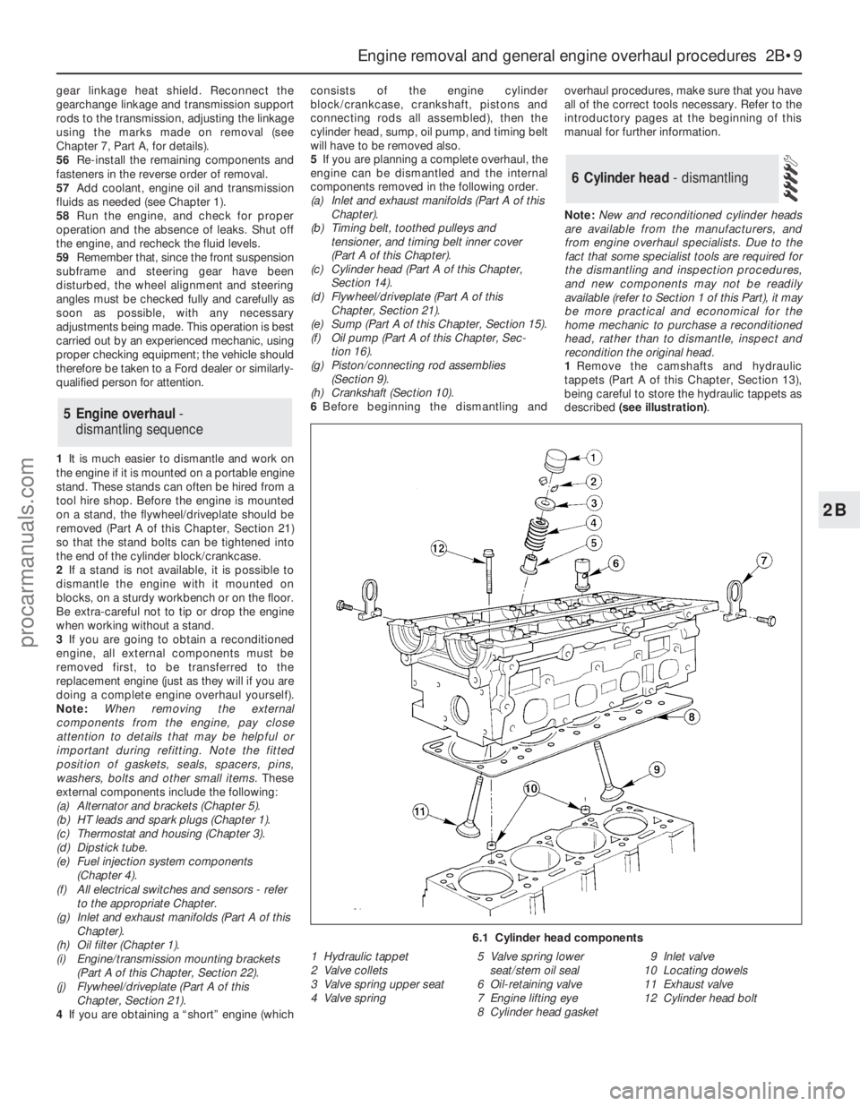
1Remove the camshafts and hydraulic
tappets (Part A of this Chapter, Section 13),
being careful to store the hydraulic tappets as
described (see illustration).
6 Cylinder head - dismantling
5 Engine overhaul-
dismantling sequence
Engine removal and general engine overhaul procedures 2B•9
2B
6.1 Cylinder head components
1 Hydraulic tappet
2 Valve collets
3 Valve spring upper seat
4 Valve spring5 Valve spring lower
seat/stem oil seal
6 Oil-retaining valve
7 Engine lifting eye
8 Cylinder head gasket9 Inlet valve
10 Locating dowels
11 Exhaust valve
12 Cylinder head bolt
procarmanuals.com
Page 145 of 279

passes the sensor tip, a signal is generated,
which is used by the ECU to determine engine
speed.
4The ridge between the 35th and 36th holes
(corresponding to 90° BTDC) is missing - this
step in the incoming signals is used by the
ECU to determine crankshaft (ie, piston)
position.
Camshaft position sensor
5This is bolted to the rear left-hand end of
the cylinder head, to register with a lobe on
the inlet camshaft. It functions in the same
way as the crankshaft speed/position sensor,
producing a series of pulses (corresponding
to No 1 cylinder at 46° ATDC); this gives the
ECU a reference point, to enable it to
determine the firing order, and operate the
injectors in the appropriate sequence.
Coolant temperature sensor
6This component, which is screwed into the
top of the thermostat housing, is an NTC
(Negative Temperature Coefficient) thermistor
- that is, a semi-conductor whose electrical
resistance decreases as its temperature
increases. It provides the ECU with a
constantly-varying (analogue) voltage signal,
corresponding to the temperature of the
engine coolant. This is used to refine the
calculations made by the ECU, when
determining the correct amount of fuel
required to achieve the ideal air/fuel mixture
ratio.
Intake air temperature sensor
7This component, which is screwed into the
underside of the air intake resonator, is also an
NTC thermistor - see the previous paragraph -
providing the ECU with a signal corresponding
to the temperature of air passing into the
engine. This is used to refine the calculations
made by the ECU, when determining the
correct amount of fuel required to achieve the
ideal air/fuel mixture ratio.
Throttle potentiometer
8This is mounted on the end of the throttle
valve spindle, to provide the ECU with a
constantly-varying (analogue) voltage signal
corresponding to the throttle opening. This
allows the ECU to register the driver’s input
when determining the amount of fuel required
by the engine.
Vehicle speed sensor
9This component is a Hall-effect generator,
mounted on the transmission’s speedometer
drive. It supplies the ECU with a series of
pulses corresponding to the vehicle’s road
speed, enabling the ECU to control features
such as the fuel shut-off on the overrun, and
to provide information for the trip computer,
adaptive damping and cruise control systems
(where fitted).
Power steering pressure switch
10This is a pressure-operated switch,
screwed into the power steering system’shigh-pressure pipe. Its contacts are normally
closed, opening when the system reaches the
specified pressure - on receiving this signal,
the ECU increases the idle speed, to
compensate for the additional load on the
engine.
Exhaust gas pressure differential
sensor
11This component measures the difference
in pressure of the exhaust gases across a
venturi (restriction) in the Exhaust Gas
Recirculation (EGR) system’s pipe, and sends
the ECU a voltage signal corresponding to the
pressure difference.
Oxygen sensor
12The oxygen sensor in the exhaust system
provides the ECU with constant feedback -
“closed-loop” control - which enables it to
adjust the mixture to provide the best possible
conditions for the catalytic converter to
operate.
13The sensor has a built-in heating element
which is controlled by the ECU, in order to
bring the sensor’s tip to an efficient operating
temperature as rapidly as possible. The
sensor’s tip is sensitive to oxygen, and sends
the ECU a varying voltage depending on the
amount of oxygen in the exhaust gases. If the
intake air/fuel mixture is too rich, the exhaust
gases are low in oxygen, so the sensor sends
a low-voltage signal, the voltage rising as the
mixture weakens and the amount of oxygen in
the exhaust gases rises. Peak conversion
efficiency of all major pollutants occurs if the
intake air/fuel mixture is maintained at the
chemically-correct ratio for the complete
combustion of petrol, of 14.7 parts (by weight)
of air to 1 part of fuel (the “stoichiometric”
ratio). The sensor output voltage alters sharply
around this point, the ECU using the signal
change as a reference point, and correcting
the air/fuel mixture by altering the fuel injector
pulse width.
Air conditioning system
14Two pressure-operated switches and the
compressor clutch solenoid are connected to
the ECU, to enable it to determine how the
system is operating. The ECU can increase
idle speed or switch off the system, as
necessary, so that normal vehicle operation
and driveability are not impaired. See Chapter
3 for further details, but note that diagnosis
and repair should be left to a dealer service
department or air conditioning specialist.
Automatic transmission
15In addition to the driver’s controls, the
transmission has a speed sensor, a fluid
temperature sensor (built into the solenoid
valve unit), and a selector lever position
sensor. All of these are connected to the ECU,
to enable it to control the transmission
through the solenoid valve unit. See Part B of
Chapter 7 for further details.
Testing
ECU (Electronic Control Unit)
16 Do notattempt to “test” the ECU with any
kind of equipment. If it is thought to be faulty,
take the vehicle to a Ford dealer for the entire
electronic control system to be checked using
the proper diagnostic equipment. Only if all
other possibilities have been eliminated should
the ECU be considered at fault, and replaced.
Air mass meter
17Testing of this component is beyond the
scope of the DIY mechanic, and should be left
to a Ford dealer.
Crankshaft speed/position sensor
18Unplug the electrical connector from the
sensor.
19Using an ohmmeter, measure the
resistance between the sensor terminals.
Compare this reading to the one listed in the
Specifications Section at the beginning of this
Chapter. If the indicated resistance is not
within the specified range, renew the sensor.
20Plug in the sensor’s electrical connector
on completion.
Camshaft position sensor
21The procedure is as described in
paragraphs 18 to 20 above.
Coolant temperature sensor
22Refer to Chapter 3.
Intake air temperature sensor
23Unplug the electrical connector from the
sensor.
24Using an ohmmeter, measure the
resistance between the sensor terminals.
Depending on the temperature of the sensor
tip, the resistance measured will vary, but it
should be within the broad limits given in the
Specifications Section of this Chapter. If the
sensor’s temperature is varied - by placing it
in a freezer for a while, or by warming it gently
- its resistance should alter accordingly.
25If the results obtained show the sensor to
be faulty, renew it.
Throttle potentiometer
26Remove the plenum chamber (see
Chapter 4) and unplug the potentiometer’s
electrical connector.
27Using an ohmmeter, measure the
resistance between the unit’s terminals - first
between the centre terminal and one of the
outer two, then from the centre to the
remaining outer terminal. The resistance
should be within the limits given in the
Specifications Section of this Chapter, and
should alter smoothlyas the throttle valve is
moved from the fully-closed (idle speed)
position to fully open and back again.
28If the resistance measured is significantly
different from the specified value, if there are
any breaks in continuity, or if the reading
fluctuates erratically as the throttle is
operated, the potentiometer is faulty, and
must be renewed.
Emissions control systems 6•11
6
procarmanuals.com
Page 208 of 279

Main light, auxiliary foglight and rear
foglight combination switch
Note:From July 1994 a rvised main light
switch was introduced; this was fitted as
standard in production. If the revised switch is
to be fitted to a pre-July 1994 model, an
adapter lead will also be required to prevent
electrical damage ocurring. Refer to your Ford
dealer for further information
9Disconnect the battery negative (earth) lead
(refer to Chapter 5, Section 1).
10Carefully prise the switch panel from the
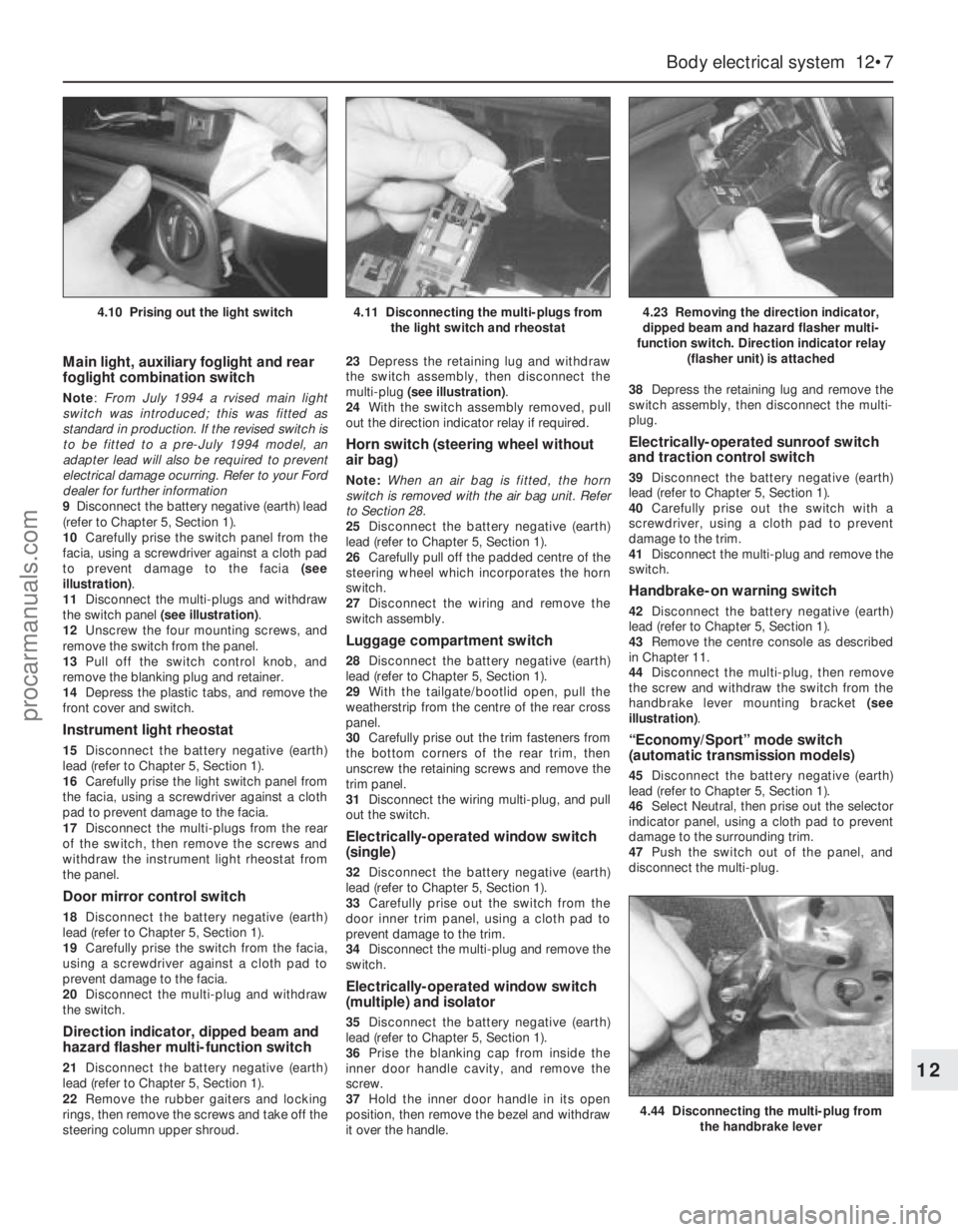
facia, using a screwdriver against a cloth pad
to prevent damage to the facia (see
illustration).
11Disconnect the multi-plugs and withdraw
the switch panel (see illustration).
12Unscrew the four mounting screws, and
remove the switch from the panel.
13Pull off the switch control knob, and
remove the blanking plug and retainer.
14Depress the plastic tabs, and remove the
front cover and switch.
Instrument light rheostat
15Disconnect the battery negative (earth)
lead (refer to Chapter 5, Section 1).
16Carefully prise the light switch panel from
the facia, using a screwdriver against a cloth
pad to prevent damage to the facia.
17Disconnect the multi-plugs from the rear
of the switch, then remove the screws and
withdraw the instrument light rheostat from
the panel.
Door mirror control switch
18Disconnect the battery negative (earth)
lead (refer to Chapter 5, Section 1).
19Carefully prise the switch from the facia,
using a screwdriver against a cloth pad to
prevent damage to the facia.
20Disconnect the multi-plug and withdraw
the switch.
Direction indicator, dipped beam and
hazard flasher multi-function switch
21Disconnect the battery negative (earth)
lead (refer to Chapter 5, Section 1).
22Remove the rubber gaiters and locking
rings, then remove the screws and take off the
steering column upper shroud.23Depress the retaining lug and withdraw
the switch assembly, then disconnect the
multi-plug (see illustration).
24With the switch assembly removed, pull
out the direction indicator relay if required.
Horn switch (steering wheel without
air bag)
Note:When an air bag is fitted, the horn
switch is removed with the air bag unit. Refer
to Section 28.
25Disconnect the battery negative (earth)
lead (refer to Chapter 5, Section 1).
26Carefully pull off the padded centre of the
steering wheel which incorporates the horn
switch.
27Disconnect the wiring and remove the
switch assembly.
Luggage compartment switch
28Disconnect the battery negative (earth)
lead (refer to Chapter 5, Section 1).
29With the tailgate/bootlid open, pull the
weatherstrip from the centre of the rear cross
panel.
30Carefully prise out the trim fasteners from
the bottom corners of the rear trim, then
unscrew the retaining screws and remove the
trim panel.
31Disconnect the wiring multi-plug, and pull
out the switch.
Electrically-operated window switch
(single)
32Disconnect the battery negative (earth)
lead (refer to Chapter 5, Section 1).
33Carefully prise out the switch from the
door inner trim panel, using a cloth pad to
prevent damage to the trim.
34Disconnect the multi-plug and remove the
switch.
Electrically-operated window switch
(multiple) and isolator
35Disconnect the battery negative (earth)
lead (refer to Chapter 5, Section 1).
36Prise the blanking cap from inside the
inner door handle cavity, and remove the
screw.
37Hold the inner door handle in its open
position, then remove the bezel and withdraw
it over the handle.38Depress the retaining lug and remove the
switch assembly, then disconnect the multi-
plug.
Electrically-operated sunroof switch
and traction control switch
39Disconnect the battery negative (earth)
lead (refer to Chapter 5, Section 1).
40Carefully prise out the switch with a
screwdriver, using a cloth pad to prevent
damage to the trim.
41Disconnect the multi-plug and remove the
switch.
Handbrake-on warning switch
42Disconnect the battery negative (earth)
lead (refer to Chapter 5, Section 1).
43Remove the centre console as described
in Chapter 11.
44Disconnect the multi-plug, then remove
the screw and withdraw the switch from the
handbrake lever mounting bracket (see
illustration).
“Economy/Sport” mode switch
(automatic transmission models)
45Disconnect the battery negative (earth)
lead (refer to Chapter 5, Section 1).
46Select Neutral, then prise out the selector
indicator panel, using a cloth pad to prevent
damage to the surrounding trim.
47Push the switch out of the panel, and
disconnect the multi-plug.
Body electrical system 12•7
12
4.44 Disconnecting the multi-plug from
the handbrake lever
4.10 Prising out the light switch4.11 Disconnecting the multi-plugs from
the light switch and rheostat4.23 Removing the direction indicator,
dipped beam and hazard flasher multi-
function switch. Direction indicator relay
(flasher unit) is attached
procarmanuals.com