1993 FORD MONDEO width
[x] Cancel search: widthPage 6 of 279
0•6General Dimensions & Weights
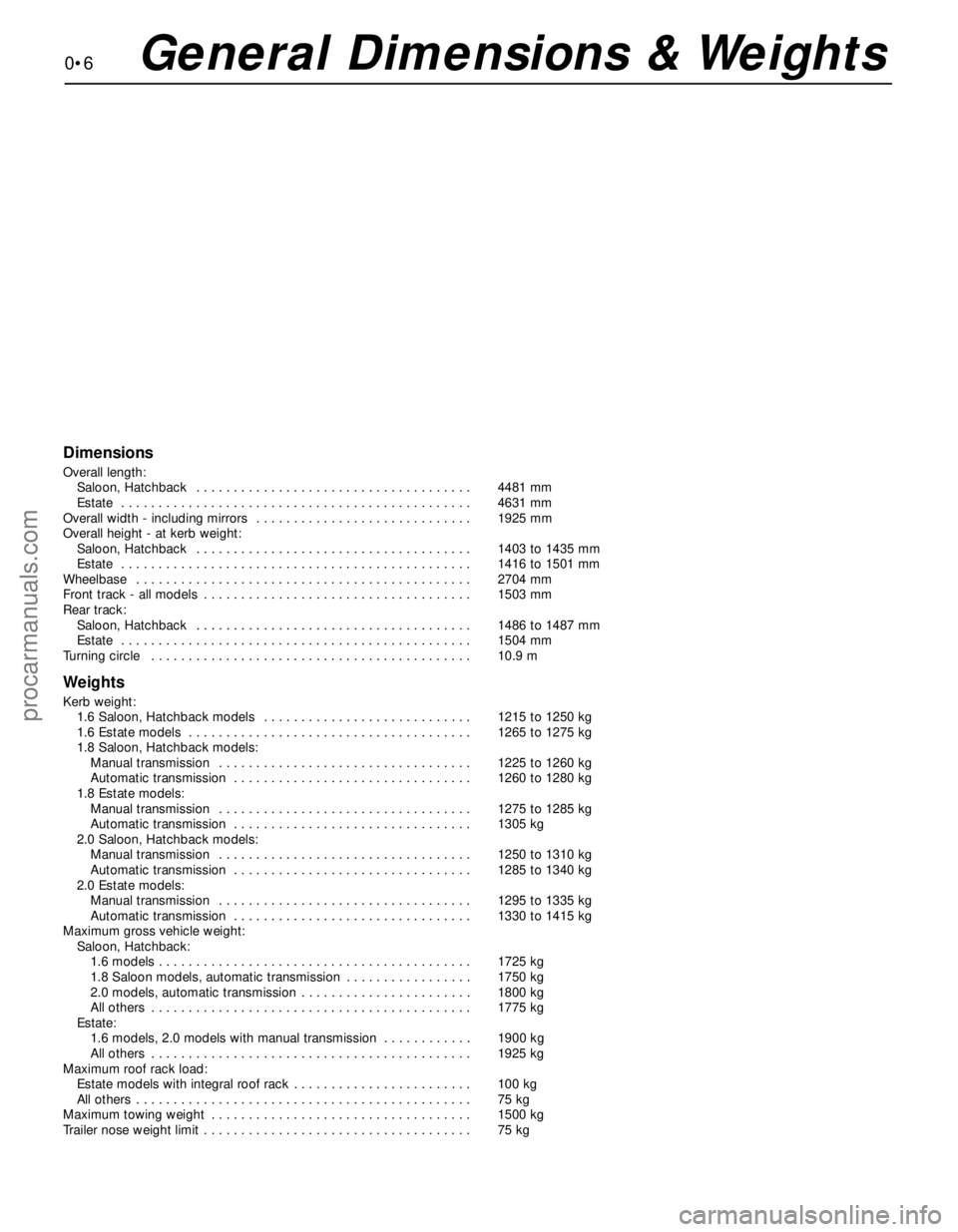
Dimensions
Overall length:
Saloon, Hatchback . . . . . . . . . . . . . . . . . . . . . . . . . . . . . . . . . . . . . 4481 mm
Estate . . . . . . . . . . . . . . . . . . . . . . . . . . . . . . . . . . . . . . . . . . . . . . . 4631 mm
Overall width - including mirrors . . . . . . . . . . . . . . . . . . . . . . . . . . . . . 1925 mm
Overall height - at kerb weight:
Saloon, Hatchback . . . . . . . . . . . . . . . . . . . . . . . . . . . . . . . . . . . . . 1403 to 1435 mm
Estate . . . . . . . . . . . . . . . . . . . . . . . . . . . . . . . . . . . . . . . . . . . . . . . 1416 to 1501 mm
Wheelbase . . . . . . . . . . . . . . . . . . . . . . . . . . . . . . . . . . . . . . . . . . . . . 2704 mm
Front track - all models . . . . . . . . . . . . . . . . . . . . . . . . . . . . . . . . . . . . 1503 mm
Rear track:
Saloon, Hatchback . . . . . . . . . . . . . . . . . . . . . . . . . . . . . . . . . . . . . 1486 to 1487 mm
Estate . . . . . . . . . . . . . . . . . . . . . . . . . . . . . . . . . . . . . . . . . . . . . . . 1504 mm
Turning circle . . . . . . . . . . . . . . . . . . . . . . . . . . . . . . . . . . . . . . . . . . . 10.9 m
Weights
Kerb weight:
1.6 Saloon, Hatchback models . . . . . . . . . . . . . . . . . . . . . . . . . . . . 1215 to 1250 kg
1.6 Estate models . . . . . . . . . . . . . . . . . . . . . . . . . . . . . . . . . . . . . . 1265 to 1275 kg
1.8 Saloon, Hatchback models:
Manual transmission . . . . . . . . . . . . . . . . . . . . . . . . . . . . . . . . . . 1225 to 1260 kg
Automatic transmission . . . . . . . . . . . . . . . . . . . . . . . . . . . . . . . . 1260 to 1280 kg
1.8 Estate models:
Manual transmission . . . . . . . . . . . . . . . . . . . . . . . . . . . . . . . . . . 1275 to 1285 kg
Automatic transmission . . . . . . . . . . . . . . . . . . . . . . . . . . . . . . . . 1305 kg
2.0 Saloon, Hatchback models:
Manual transmission . . . . . . . . . . . . . . . . . . . . . . . . . . . . . . . . . . 1250 to 1310 kg
Automatic transmission . . . . . . . . . . . . . . . . . . . . . . . . . . . . . . . . 1285 to 1340 kg
2.0 Estate models:
Manual transmission . . . . . . . . . . . . . . . . . . . . . . . . . . . . . . . . . . 1295 to 1335 kg
Automatic transmission . . . . . . . . . . . . . . . . . . . . . . . . . . . . . . . . 1330 to 1415 kg
Maximum gross vehicle weight:
Saloon, Hatchback:
1.6 models . . . . . . . . . . . . . . . . . . . . . . . . . . . . . . . . . . . . . . . . . . 1725 kg
1.8 Saloon models, automatic transmission . . . . . . . . . . . . . . . . . 1750 kg
2.0 models, automatic transmission . . . . . . . . . . . . . . . . . . . . . . . 1800 kg
All others . . . . . . . . . . . . . . . . . . . . . . . . . . . . . . . . . . . . . . . . . . . 1775 kg
Estate:
1.6 models, 2.0 models with manual transmission . . . . . . . . . . . . 1900 kg
All others . . . . . . . . . . . . . . . . . . . . . . . . . . . . . . . . . . . . . . . . . . . 1925 kg
Maximum roof rack load:
Estate models with integral roof rack . . . . . . . . . . . . . . . . . . . . . . . . 100 kg
All others . . . . . . . . . . . . . . . . . . . . . . . . . . . . . . . . . . . . . . . . . . . . . 75 kg
Maximum towing weight . . . . . . . . . . . . . . . . . . . . . . . . . . . . . . . . . . . 1500 kg
Trailer nose weight limit . . . . . . . . . . . . . . . . . . . . . . . . . . . . . . . . . . . . 75 kg
procarmanuals.com
Page 10 of 279
0•10
MExamine the handbrake mechanism,
checking for frayed or broken cables,
excessive corrosion, or wear or insecurity of
the linkage. Check that the mechanism works
on each relevant wheel, and releases fully,
without binding.
MIt is not possible to test brake efficiency
without special equipment, but a road test
can be carried out later to check that the
vehicle pulls up in a straight line.
Fuel and exhaust systems
MInspect the fuel tank (including the filler
cap), fuel pipes, hoses and unions. All
components must be secure and free from
leaks.
MExamine the exhaust system over its entire
length, checking for any damaged, broken or
missing mountings, security of the retaining
clamps and rust or corrosion.
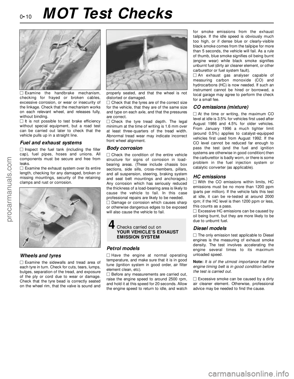
Wheels and tyres
MExamine the sidewalls and tread area of
each tyre in turn. Check for cuts, tears, lumps,
bulges, separation of the tread, and exposure
of the ply or cord due to wear or damage.
Check that the tyre bead is correctly seated
on the wheel rim, that the valve is sound andproperly seated, and that the wheel is not
distorted or damaged.
MCheck that the tyres are of the correct size
for the vehicle, that they are of the same size
and type on each axle, and that the pressures
are correct.
MCheck the tyre tread depth. The legal
minimum at the time of writing is 1.6 mm over
at least three-quarters of the tread width.
Abnormal tread wear may indicate incorrect
front wheel alignment.
Body corrosion
MCheck the condition of the entire vehicle
structure for signs of corrosion in load-
bearing areas. (These include chassis box
sections, side sills, cross-members, pillars,
and all suspension, steering, braking system
and seat belt mountings and anchorages.)
Any corrosion which has seriously reduced
the thickness of a load-bearing area is likely to
cause the vehicle to fail. In this case
professional repairs are likely to be needed.
MDamage or corrosion which causes sharp
or otherwise dangerous edges to be exposed
will also cause the vehicle to fail.
Petrol models
MHave the engine at normal operating
temperature, and make sure that it is in good
tune (ignition system in good order, air filter
element clean, etc).
MBefore any measurements are carried out,
raise the engine speed to around 2500 rpm,
and hold it at this speed for 20 seconds. Allow
the engine speed to return to idle, and watchfor smoke emissions from the exhaust
tailpipe. If the idle speed is obviously much
too high, or if dense blue or clearly-visible
black smoke comes from the tailpipe for more
than 5 seconds, the vehicle will fail. As a rule
of thumb, blue smoke signifies oil being burnt
(engine wear) while black smoke signifies
unburnt fuel (dirty air cleaner element, or other
carburettor or fuel system fault).
MAn exhaust gas analyser capable of
measuring carbon monoxide (CO) and
hydrocarbons (HC) is now needed. If such an
instrument cannot be hired or borrowed, a
local garage may agree to perform the check
for a small fee.
CO emissions (mixture)
MAt the time or writing, the maximum CO
level at idle is 3.5% for vehicles first used after
August 1986 and 4.5% for older vehicles.
From January 1996 a much tighter limit
(around 0.5%) applies to catalyst-equipped
vehicles first used from August 1992. If the
CO level cannot be reduced far enough to
pass the test (and the fuel and ignition
systems are otherwise in good condition) then
the carburettor is badly worn, or there is some
problem in the fuel injection system or
catalytic converter (as applicable).
HC emissionsMWith the CO emissions within limits, HC
emissions must be no more than 1200 ppm
(parts per million). If the vehicle fails this test
at idle, it can be re-tested at around 2000
rpm; if the HC level is then 1200 ppm or less,
this counts as a pass.
MExcessive HC emissions can be caused by
oil being burnt, but they are more likely to be
due to unburnt fuel.
Diesel models
MThe only emission test applicable to Diesel
engines is the measuring of exhaust smoke
density. The test involves accelerating the
engine several times to its maximum
unloaded speed.
Note: It is of the utmost importance that the
engine timing belt is in good condition before
the test is carried out.
M
Excessive smoke can be caused by a dirty
air cleaner element. Otherwise, professional
advice may be needed to find the cause.
4Checks carried out on
YOUR VEHICLE’S EXHAUST
EMISSION SYSTEM
MOT Test Checks
procarmanuals.com
Page 51 of 279
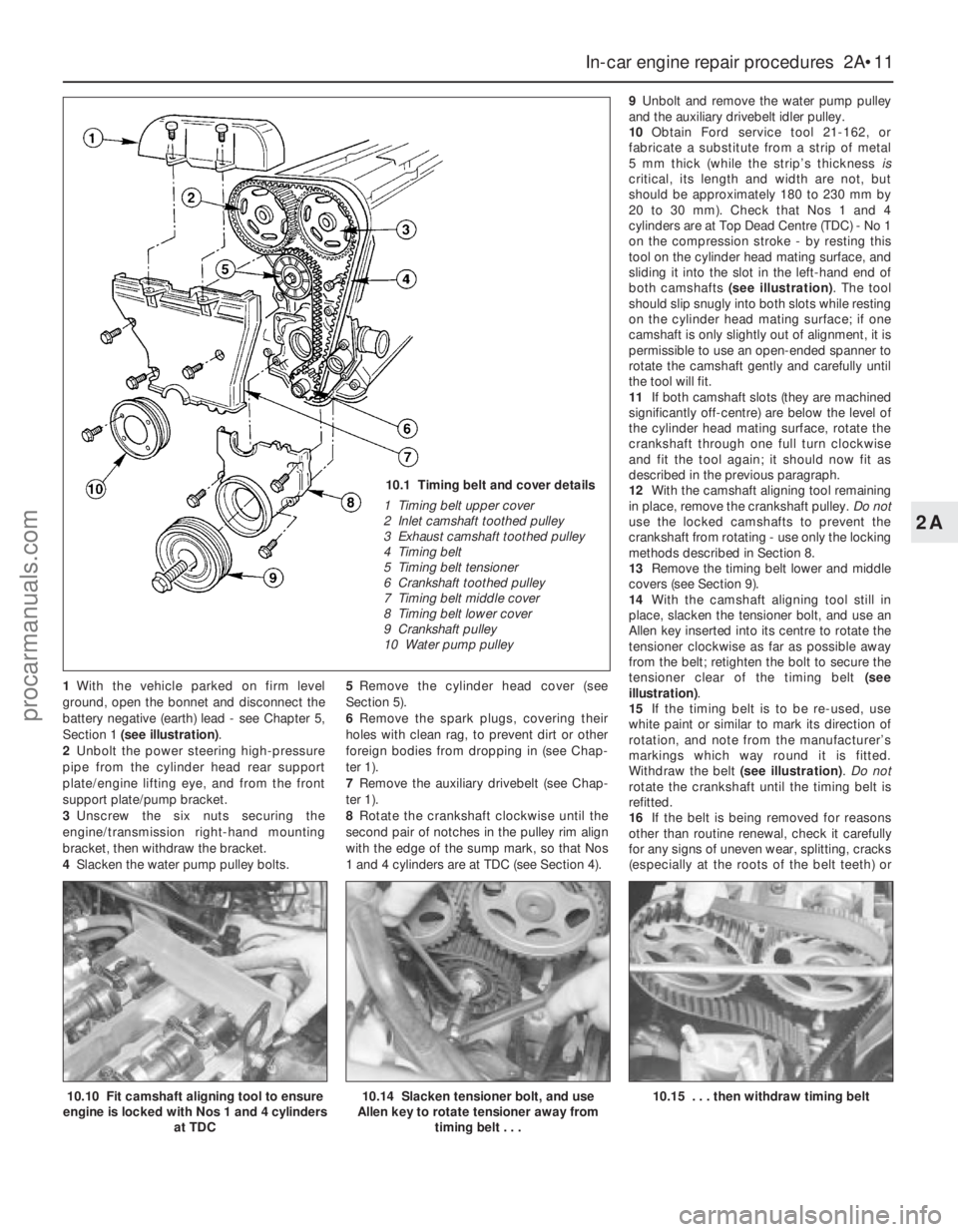
1With the vehicle parked on firm level
ground, open the bonnet and disconnect the
battery negative (earth) lead - see Chapter 5,
Section 1 (see illustration).
2Unbolt the power steering high-pressure
pipe from the cylinder head rear support
plate/engine lifting eye, and from the front
support plate/pump bracket.
3Unscrew the six nuts securing the
engine/transmission right-hand mounting
bracket, then withdraw the bracket.
4Slacken the water pump pulley bolts.5Remove the cylinder head cover (see
Section 5).
6Remove the spark plugs, covering their
holes with clean rag, to prevent dirt or other
foreign bodies from dropping in (see Chap-
ter 1).
7Remove the auxiliary drivebelt (see Chap-
ter 1).
8Rotate the crankshaft clockwise until the
second pair of notches in the pulley rim align
with the edge of the sump mark, so that Nos
1 and 4 cylinders are at TDC (see Section 4).9Unbolt and remove the water pump pulley
and the auxiliary drivebelt idler pulley.
10Obtain Ford service tool 21-162, or
fabricate a substitute from a strip of metal
5 mm thick (while the strip’s thickness is
critical, its length and width are not, but
should be approximately 180 to 230 mm by
20 to 30 mm). Check that Nos 1 and 4
cylinders are at Top Dead Centre (TDC) - No 1
on the compression stroke - by resting this
tool on the cylinder head mating surface, and
sliding it into the slot in the left-hand end of
both camshafts (see illustration). The tool
should slip snugly into both slots while resting
on the cylinder head mating surface; if one
camshaft is only slightly out of alignment, it is
permissible to use an open-ended spanner to
rotate the camshaft gently and carefully until
the tool will fit.
11If both camshaft slots (they are machined
significantly off-centre) are below the level of
the cylinder head mating surface, rotate the
crankshaft through one full turn clockwise
and fit the tool again; it should now fit as
described in the previous paragraph.
12With the camshaft aligning tool remaining
in place, remove the crankshaft pulley. Do not
use the locked camshafts to prevent the
crankshaft from rotating - use only the locking
methods described in Section 8.
13Remove the timing belt lower and middle
covers (see Section 9).
14With the camshaft aligning tool still in
place, slacken the tensioner bolt, and use an
Allen key inserted into its centre to rotate the
tensioner clockwise as far as possible away
from the belt; retighten the bolt to secure the
tensioner clear of the timing belt (see
illustration).
15If the timing belt is to be re-used, use
white paint or similar to mark its direction of
rotation, and note from the manufacturer’s
markings which way round it is fitted.
Withdraw the belt (see illustration). Do not
rotate the crankshaft until the timing belt is
refitted.
16If the belt is being removed for reasons
other than routine renewal, check it carefully
for any signs of uneven wear, splitting, cracks
(especially at the roots of the belt teeth) or
In-car engine repair procedures 2A•11
2A
10.10 Fit camshaft aligning tool to ensure
engine is locked with Nos 1 and 4 cylinders
at TDC10.14 Slacken tensioner bolt, and use
Allen key to rotate tensioner away from
timing belt . . .10.15 . . . then withdraw timing belt
10.1 Timing belt and cover details
1 Timing belt upper cover
2 Inlet camshaft toothed pulley
3 Exhaust camshaft toothed pulley
4 Timing belt
5 Timing belt tensioner
6 Crankshaft toothed pulley
7 Timing belt middle cover
8 Timing belt lower cover
9 Crankshaft pulley
10 Water pump pulley
procarmanuals.com
Page 55 of 279
wear (scoring, pitting etc) and for ovality, and
renew if necessary.
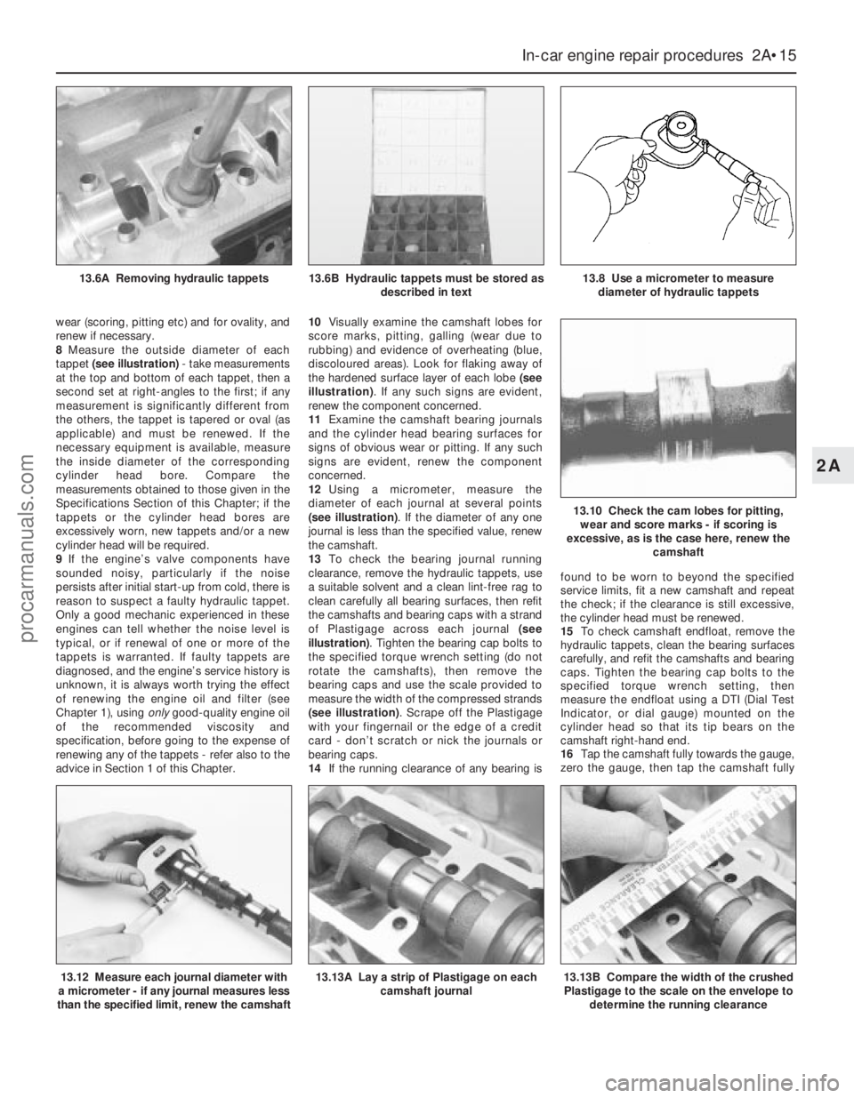
8Measure the outside diameter of each
tappet (see illustration)- take measurements
at the top and bottom of each tappet, then a
second set at right-angles to the first; if any
measurement is significantly different from
the others, the tappet is tapered or oval (as
applicable) and must be renewed. If the
necessary equipment is available, measure
the inside diameter of the corresponding
cylinder head bore. Compare the
measurements obtained to those given in the
Specifications Section of this Chapter; if the
tappets or the cylinder head bores are
excessively worn, new tappets and/or a new
cylinder head will be required.
9If the engine’s valve components have
sounded noisy, particularly if the noise
persists after initial start-up from cold, there is
reason to suspect a faulty hydraulic tappet.
Only a good mechanic experienced in these
engines can tell whether the noise level is
typical, or if renewal of one or more of the
tappets is warranted. If faulty tappets are
diagnosed, and the engine’s service history is
unknown, it is always worth trying the effect
of renewing the engine oil and filter (see
Chapter 1), using onlygood-quality engine oil
of the recommended viscosity and
specification, before going to the expense of
renewing any of the tappets - refer also to the
advice in Section 1 of this Chapter.10Visually examine the camshaft lobes for
score marks, pitting, galling (wear due to
rubbing) and evidence of overheating (blue,
discoloured areas). Look for flaking away of
the hardened surface layer of each lobe (see
illustration). If any such signs are evident,
renew the component concerned.
11Examine the camshaft bearing journals
and the cylinder head bearing surfaces for
signs of obvious wear or pitting. If any such
signs are evident, renew the component
concerned.
12Using a micrometer, measure the
diameter of each journal at several points
(see illustration). If the diameter of any one
journal is less than the specified value, renew
the camshaft.
13To check the bearing journal running
clearance, remove the hydraulic tappets, use
a suitable solvent and a clean lint-free rag to
clean carefully all bearing surfaces, then refit
the camshafts and bearing caps with a strand
of Plastigage across each journal (see
illustration). Tighten the bearing cap bolts to
the specified torque wrench setting (do not
rotate the camshafts), then remove the
bearing caps and use the scale provided to
measure the width of the compressed strands
(see illustration). Scrape off the Plastigage
with your fingernail or the edge of a credit
card - don’t scratch or nick the journals or
bearing caps.
14If the running clearance of any bearing isfound to be worn to beyond the specified
service limits, fit a new camshaft and repeat
the check; if the clearance is still excessive,
the cylinder head must be renewed.
15To check camshaft endfloat, remove the
hydraulic tappets, clean the bearing surfaces
carefully, and refit the camshafts and bearing
caps. Tighten the bearing cap bolts to the
specified torque wrench setting, then
measure the endfloat using a DTI (Dial Test
Indicator, or dial gauge) mounted on the
cylinder head so that its tip bears on the
camshaft right-hand end.
16Tap the camshaft fully towards the gauge,
zero the gauge, then tap the camshaft fully
In-car engine repair procedures 2A•15
2A
13.12 Measure each journal diameter with
a micrometer - if any journal measures less
than the specified limit, renew the camshaft13.13A Lay a strip of Plastigage on each
camshaft journal13.13B Compare the width of the crushed
Plastigage to the scale on the envelope to
determine the running clearance
13.6A Removing hydraulic tappets13.6B Hydraulic tappets must be stored as
described in text13.8 Use a micrometer to measure
diameter of hydraulic tappets
13.10 Check the cam lobes for pitting,
wear and score marks - if scoring is
excessive, as is the case here, renew the
camshaft
procarmanuals.com
Page 85 of 279
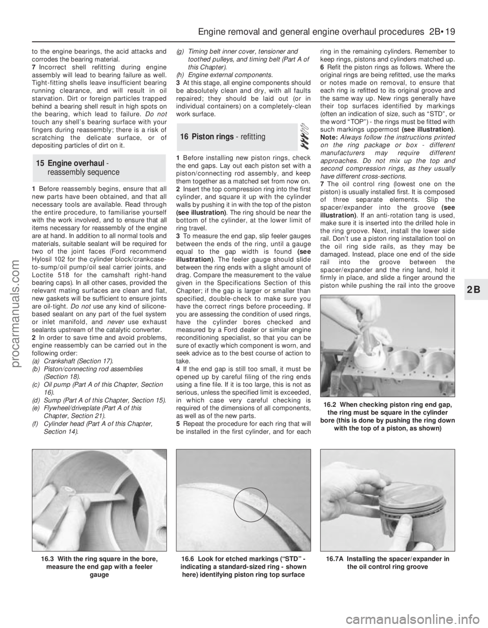
to the engine bearings, the acid attacks and
corrodes the bearing material.
7Incorrect shell refitting during engine
assembly will lead to bearing failure as well.
Tight-fitting shells leave insufficient bearing
running clearance, and will result in oil
starvation. Dirt or foreign particles trapped
behind a bearing shell result in high spots on
the bearing, which lead to failure. Do not
touch any shell’s bearing surface with your
fingers during reassembly; there is a risk of
scratching the delicate surface, or of
depositing particles of dirt on it.
1Before reassembly begins, ensure that all
new parts have been obtained, and that all
necessary tools are available. Read through
the entire procedure, to familiarise yourself
with the work involved, and to ensure that all
items necessary for reassembly of the engine
are at hand. In addition to all normal tools and
materials, suitable sealant will be required for
two of the joint faces (Ford recommend
Hylosil 102 for the cylinder block/crankcase-
to-sump/oil pump/oil seal carrier joints, and
Loctite 518 for the camshaft right-hand
bearing caps). In all other cases, provided the
relevant mating surfaces are clean and flat,
new gaskets will be sufficient to ensure joints
are oil-tight. Do notuse any kind of silicone-
based sealant on any part of the fuel system
or inlet manifold, and neveruse exhaust
sealants upstream of the catalytic converter.
2In order to save time and avoid problems,
engine reassembly can be carried out in the
following order:
(a) Crankshaft (Section 17).
(b) Piston/connecting rod assemblies
(Section 18).
(c) Oil pump (Part A of this Chapter, Section
16).
(d) Sump (Part A of this Chapter, Section 15).
(e) Flywheel/driveplate (Part A of this
Chapter, Section 21).
(f) Cylinder head (Part A of this Chapter,
Section 14).(g) Timing belt inner cover, tensioner and
toothed pulleys, and timing belt (Part A of
this Chapter).
(h) Engine external components.
3At this stage, all engine components should
be absolutely clean and dry, with all faults
repaired; they should be laid out (or in
individual containers) on a completely-clean
work surface.
1Before installing new piston rings, check
the end gaps. Lay out each piston set with a
piston/connecting rod assembly, and keep
them together as a matched set from now on.
2Insert the top compression ring into the first
cylinder, and square it up with the cylinder
walls by pushing it in with the top of the piston
(see illustration). The ring should be near the
bottom of the cylinder, at the lower limit of
ring travel.
3To measure the end gap, slip feeler gauges
between the ends of the ring, until a gauge
equal to the gap width is found (see
illustration). The feeler gauge should slide
between the ring ends with a slight amount of
drag. Compare the measurement to the value
given in the Specifications Section of this
Chapter; if the gap is larger or smaller than
specified, double-check to make sure you
have the correct rings before proceeding. If
you are assessing the condition of used rings,
have the cylinder bores checked and
measured by a Ford dealer or similar engine
reconditioning specialist, so that you can be
sure of exactly which component is worn, and
seek advice as to the best course of action to
take.
4If the end gap is still too small, it must be
opened up by careful filing of the ring ends
using a fine file. If it is too large, this is not as
serious, unless the specified limit is exceeded,
in which case very careful checking is
required of the dimensions of all components,
as well as of the new parts.
5Repeat the procedure for each ring that will
be installed in the first cylinder, and for eachring in the remaining cylinders. Remember to
keep rings, pistons and cylinders matched up.
6Refit the piston rings as follows. Where the
original rings are being refitted, use the marks
or notes made on removal, to ensure that
each ring is refitted to its original groove and
the same way up. New rings generally have
their top surfaces identified by markings
(often an indication of size, such as “STD”, or
the word “TOP”) - the rings must be fitted with
such markings uppermost (see illustration).
Note:Always follow the instructions printed
on the ring package or box - different
manufacturers may require different
approaches. Do not mix up the top and
second compression rings, as they usually
have different cross-sections.
7The oil control ring (lowest one on the
piston) is usually installed first. It is composed
of three separate elements. Slip the
spacer/expander into the groove (see
illustration). If an anti-rotation tang is used,
make sure it is inserted into the drilled hole in
the ring groove. Next, install the lower side
rail. Don’t use a piston ring installation tool on
the oil ring side rails, as they may be
damaged. Instead, place one end of the side
rail into the groove between the
spacer/expander and the ring land, hold it
firmly in place, and slide a finger around the
piston while pushing the rail into the groove
16 Piston rings - refitting
15 Engine overhaul -
reassembly sequence
Engine removal and general engine overhaul procedures 2B•19
2B
16.7A Installing the spacer/expander in
the oil control ring groove
16.2 When checking piston ring end gap,
the ring must be square in the cylinder
bore (this is done by pushing the ring down
with the top of a piston, as shown)
16.3 With the ring square in the bore,
measure the end gap with a feeler
gauge16.6 Look for etched markings (“STD” -
indicating a standard-sized ring - shown
here) identifying piston ring top surface
procarmanuals.com
Page 86 of 279
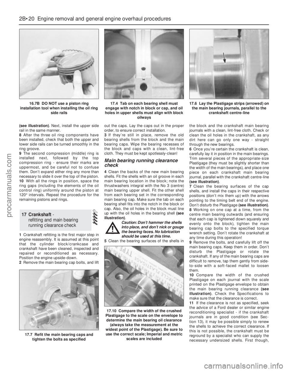
(see illustration). Next, install the upper side
rail in the same manner.
8After the three oil ring components have
been installed, check that both the upper and
lower side rails can be turned smoothly in the
ring groove.
9The second compression (middle) ring is
installed next, followed by the top
compression ring - ensure their marks are
uppermost, and be careful not to confuse
them. Don’t expand either ring any more than
necessary to slide it over the top of the piston.
10With all the rings in position, space the
ring gaps (including the elements of the oil
control ring) uniformly around the piston at
120° intervals. Repeat the procedure for the
remaining pistons and rings.
1Crankshaft refitting is the first major step in
engine reassembly. It is assumed at this point
that the cylinder block/crankcase and
crankshaft have been cleaned, inspected and
repaired or reconditioned as necessary.
Position the engine upside-down.
2Remove the main bearing cap bolts, and liftout the caps. Lay the caps out in the proper
order, to ensure correct installation.
3If they’re still in place, remove the old
bearing shells from the block and the main
bearing caps. Wipe the bearing recesses of
the block and caps with a clean, lint-free
cloth. They must be kept spotlessly-clean!
Main bearing running clearance
check
4Clean the backs of the new main bearing
shells. Fit the shells with an oil groove in each
main bearing location in the block; note the
thrustwashers integral with the No 3 (centre)
main bearing upper shell. Fit the other shell
from each bearing set in the corresponding
main bearing cap. Make sure the tab on each
bearing shell fits into the notch in the block or
cap. Also, the oil holes in the block must line
up with the oil holes in the bearing shell (see
illustration).
Caution: Don’t hammer the shells
into place, and don’t nick or gouge
the bearing faces. No lubrication
should be used at this time.
5Clean the bearing surfaces of the shells inthe block and the crankshaft main bearing
journals with a clean, lint-free cloth. Check or
clean the oil holes in the crankshaft, as any
dirt here can go only one way - straight
through the new bearings.
6Once you’re certain the crankshaft is clean,
carefully lay it in position in the main bearings.
Trim several pieces of the appropriate-size
Plastigage (they must be slightly shorter than
the width of the main bearings), and place one
piece on each crankshaft main bearing
journal, parallel with the crankshaft centre-line
(see illustration).
7Clean the bearing surfaces of the cap
shells, and install the caps in their respective
positions (don’t mix them up) with the arrows
pointing to the timing belt end of the engine.
Don’t disturb the Plastigage (see illustration).
8Working on one cap at a time, from the
centre main bearing outwards (and ensuring
that each cap is tightened down squarely and
evenly onto the block), tighten the main
bearing cap bolts to the specified torque
wrench setting. Don’t rotate the crankshaft at
any time during this operation!
9Remove the bolts, and carefully lift off the
main bearing caps. Keep them in order. Don’t
disturb the Plastigage or rotate the
crankshaft. If any of the main bearing caps are
difficult to remove, tap them gently from side-
to-side with a soft-faced mallet to loosen
them.
10Compare the width of the crushed
Plastigage on each journal with the scale
printed on the Plastigage envelope to obtain
the main bearing running clearance (see
illustration). Check the Specifications to
make sure that the clearance is correct.
11If the clearance is not as specified, seek
the advice of a Ford dealer or similar engine
reconditioning specialist - if the crankshaft
journals are in good condition (see Sec-
tion 13), it may be possible simply to renew
the shells to achieve the correct clearance. If
this is not possible, the crankshaft must be
reground by a specialist who can supply the
necessary undersized shells. First though,
17 Crankshaft-
refitting and main bearing
running clearance check
2B•20 Engine removal and general engine overhaul procedures
16.7B DO NOT use a piston ring
installation tool when installing the oil ring
side rails17.4 Tab on each bearing shell must
engage with notch in block or cap, and oil
holes in upper shells must align with block
oilways17.6 Lay the Plastigage strips (arrowed) on
the main bearing journals, parallel to the
crankshaft centre-line
17.7 Refit the main bearing caps and
tighten the bolts as specified
17.10 Compare the width of the crushed
Plastigage to the scale on the envelope to
determine the main bearing oil clearance
(always take the measurement at the
widest point of the Plastigage). Be sure to
use the correct scale; Imperial and metric
scales are included
procarmanuals.com
Page 88 of 279
rod’s big-end onto the crankpin. The piston
rings may try to pop out of the ring
compressor just before entering the cylinder
bore, so keep some pressure on the ring
compressor. Work slowly, and if any
resistance is felt as the piston enters the
cylinder, stop immediately. Find out what’s
binding, and fix it before proceeding. Do not,
for any reason, force the piston into the
cylinder - you might break a ring and/or the
piston.
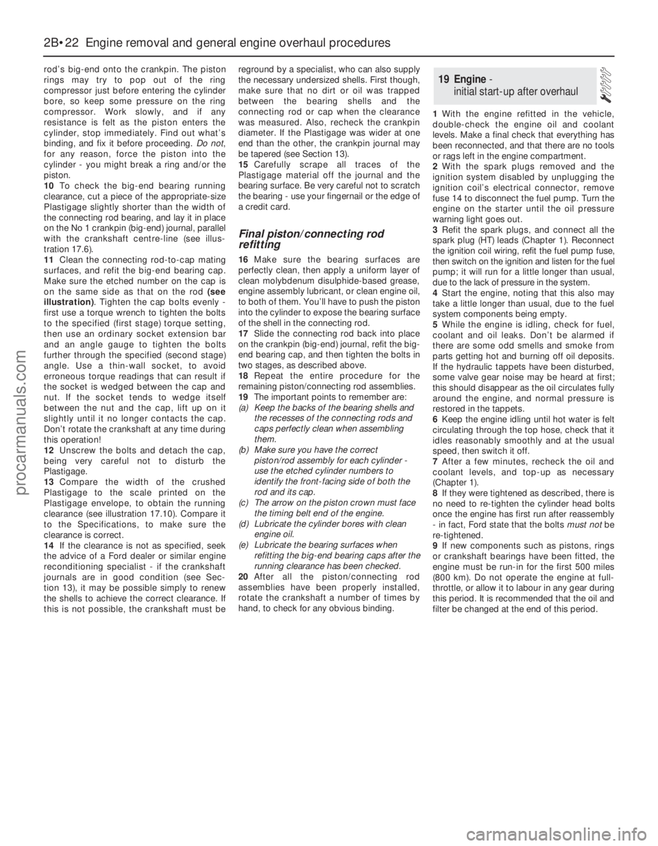
10To check the big-end bearing running
clearance, cut a piece of the appropriate-size
Plastigage slightly shorter than the width of
the connecting rod bearing, and lay it in place
on the No 1 crankpin (big-end) journal, parallel
with the crankshaft centre-line (see illus-
tration 17.6).
11Clean the connecting rod-to-cap mating
surfaces, and refit the big-end bearing cap.
Make sure the etched number on the cap is
on the same side as that on the rod (see
illustration). Tighten the cap bolts evenly -
first use a torque wrench to tighten the bolts
to the specified (first stage) torque setting,
then use an ordinary socket extension bar
and an angle gauge to tighten the bolts
further through the specified (second stage)
angle. Use a thin-wall socket, to avoid
erroneous torque readings that can result if
the socket is wedged between the cap and
nut. If the socket tends to wedge itself
between the nut and the cap, lift up on it
slightly until it no longer contacts the cap.
Don’t rotate the crankshaft at any time during
this operation!
12Unscrew the bolts and detach the cap,
being very careful not to disturb the
Plastigage.
13Compare the width of the crushed
Plastigage to the scale printed on the
Plastigage envelope, to obtain the running
clearance (see illustration 17.10). Compare it
to the Specifications, to make sure the
clearance is correct.
14If the clearance is not as specified, seek
the advice of a Ford dealer or similar engine
reconditioning specialist - if the crankshaft
journals are in good condition (see Sec-
tion 13), it may be possible simply to renew
the shells to achieve the correct clearance. If
this is not possible, the crankshaft must bereground by a specialist, who can also supply
the necessary undersized shells. First though,
make sure that no dirt or oil was trapped
between the bearing shells and the
connecting rod or cap when the clearance
was measured. Also, recheck the crankpin
diameter. If the Plastigage was wider at one
end than the other, the crankpin journal may
be tapered (see Section 13).
15Carefully scrape all traces of the
Plastigage material off the journal and the
bearing surface. Be very careful not to scratch
the bearing - use your fingernail or the edge of
a credit card.
Final piston/connecting rod
refitting
16Make sure the bearing surfaces are
perfectly clean, then apply a uniform layer of
clean molybdenum disulphide-based grease,
engine assembly lubricant, or clean engine oil,
to both of them. You’ll have to push the piston
into the cylinder to expose the bearing surface
of the shell in the connecting rod.
17Slide the connecting rod back into place
on the crankpin (big-end) journal, refit the big-
end bearing cap, and then tighten the bolts in
two stages, as described above.
18Repeat the entire procedure for the
remaining piston/connecting rod assemblies.
19The important points to remember are:
(a) Keep the backs of the bearing shells and
the recesses of the connecting rods and
caps perfectly clean when assembling
them.
(b) Make sure you have the correct
piston/rod assembly for each cylinder -
use the etched cylinder numbers to
identify the front-facing side of both the
rod and its cap.
(c) The arrow on the piston crown must face
the timing belt end of the engine.
(d) Lubricate the cylinder bores with clean
engine oil.
(e) Lubricate the bearing surfaces when
refitting the big-end bearing caps after the
running clearance has been checked.
20After all the piston/connecting rod
assemblies have been properly installed,
rotate the crankshaft a number of times by
hand, to check for any obvious binding.1With the engine refitted in the vehicle,
double-check the engine oil and coolant
levels. Make a final check that everything has
been reconnected, and that there are no tools
or rags left in the engine compartment.
2With the spark plugs removed and the
ignition system disabled by unplugging the
ignition coil’s electrical connector, remove
fuse 14 to disconnect the fuel pump. Turn the
engine on the starter until the oil pressure
warning light goes out.
3Refit the spark plugs, and connect all the
spark plug (HT) leads (Chapter 1). Reconnect
the ignition coil wiring, refit the fuel pump fuse,
then switch on the ignition and listen for the fuel
pump; it will run for a little longer than usual,
due to the lack of pressure in the system.
4Start the engine, noting that this also may
take a little longer than usual, due to the fuel
system components being empty.
5While the engine is idling, check for fuel,
coolant and oil leaks. Don’t be alarmed if
there are some odd smells and smoke from
parts getting hot and burning off oil deposits.
If the hydraulic tappets have been disturbed,
some valve gear noise may be heard at first;
this should disappear as the oil circulates fully
around the engine, and normal pressure is
restored in the tappets.
6Keep the engine idling until hot water is felt
circulating through the top hose, check that it
idles reasonably smoothly and at the usual
speed, then switch it off.
7After a few minutes, recheck the oil and
coolant levels, and top-up as necessary
(Chapter 1).
8If they were tightened as described, there is
no need to re-tighten the cylinder head bolts
once the engine has first run after reassembly
- in fact, Ford state that the bolts must notbe
re-tightened.
9If new components such as pistons, rings
or crankshaft bearings have been fitted, the
engine must be run-in for the first 500 miles
(800 km). Do not operate the engine at full-
throttle, or allow it to labour in any gear during
this period. It is recommended that the oil and
filter be changed at the end of this period.
19 Engine -
initial start-up after overhaul
2B•22 Engine removal and general engine overhaul procedures
procarmanuals.com
Page 142 of 279
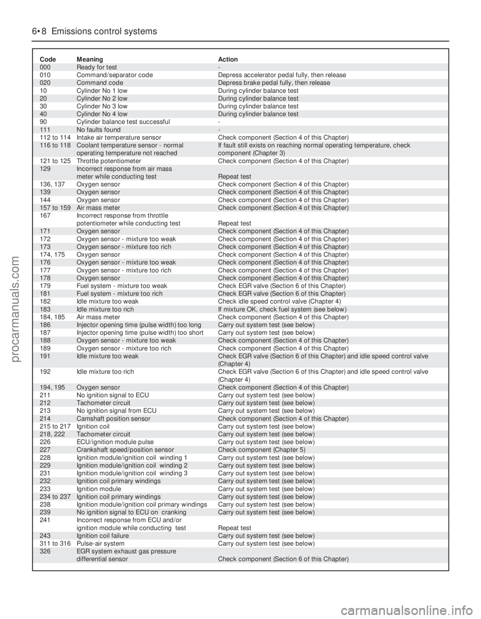
6•8 Emissions control systems
Code Meaning Action
000 Ready for test -
010 Command/separator code Depress accelerator pedal fully, then release
020 Command code Depress brake pedal fully, then release
10 Cylinder No 1 low During cylinder balance test
20 Cylinder No 2 low During cylinder balance test
30 Cylinder No 3 low During cylinder balance test
40 Cylinder No 4 low During cylinder balance test
90 Cylinder balance test successful -
111 No faults found -
112 to 114 Intake air temperature sensor Check component (Section 4 of this Chapter)116 to 118 Coolant temperature sensor - normal If fault still exists on reaching normal operating temperature, check
operating temperature not reached component (Chapter 3)
121 to 125 Throttle potentiometer Check component (Section 4 of this Chapter)129 Incorrect response from air mass
meter while conducting test Repeat test
136, 137 Oxygen sensor Check component (Section 4 of this Chapter)
139 Oxygen sensor Check component (Section 4 of this Chapter)
144 Oxygen sensor Check component (Section 4 of this Chapter)
157 to 159 Air mass meter Check component (Section 4 of this Chapter)
167 Incorrect response from throttle
potentiometer while conducting test Repeat test
171 Oxygen sensor Check component (Section 4 of this Chapter)
172 Oxygen sensor - mixture too weak Check component (Section 4 of this Chapter)
173 Oxygen sensor - mixture too rich Check component (Section 4 of this Chapter)
174, 175 Oxygen sensor Check component (Section 4 of this Chapter)
176 Oxygen sensor - mixture too weak Check component (Section 4 of this Chapter)
177 Oxygen sensor - mixture too rich Check component (Section 4 of this Chapter)
178 Oxygen sensor Check component (Section 4 of this Chapter)
179 Fuel system - mixture too weak Check EGR valve (Section 6 of this Chapter)
181 Fuel system - mixture too rich Check EGR valve (Section 6 of this Chapter)
182 Idle mixture too weak Check idle speed control valve (Chapter 4)
183 Idle mixture too rich If mixture OK, check fuel system (see below)
184, 185 Air mass meter Check component (Section 4 of this Chapter)
186 Injector opening time (pulse width) too long Carry out system test (see below)
187 Injector opening time (pulse width) too short Carry out system test (see below)
188 Oxygen sensor - mixture too weak Check component (Section 4 of this Chapter)
189 Oxygen sensor - mixture too rich Check component (Section 4 of this Chapter)191 Idle mixture too weak Check EGR valve (Section 6 of this Chapter) and idle speed control valve
(Chapter 4)
192 Idle mixture too rich Check EGR valve (Section 6 of this Chapter) and idle speed control valve
(Chapter 4)
194, 195 Oxygen sensor Check component (Section 4 of this Chapter)
211 No ignition signal to ECU Carry out system test (see below)
212 Tachometer circuit Carry out system test (see below)
213 No ignition signal from ECU Carry out system test (see below)
214 Camshaft position sensor Check component (Section 4 of this Chapter)
215 to 217 Ignition coil Carry out system test (see below)
218, 222 Tachometer circuit Carry out system test (see below)
226 ECU/ignition module pulse Carry out system test (see below)
227 Crankshaft speed/position sensor Check component (Chapter 5)
228 Ignition module/ignition coil winding 1 Carry out system test (see below)
229 Ignition module/ignition coil winding 2 Carry out system test (see below)
231 Ignition module/ignition coil winding 3 Carry out system test (see below)
232 Ignition coil primary windings Carry out system test (see below)
233 Ignition module Carry out system test (see below)
234 to 237 Ignition coil primary windings Carry out system test (see below)
238 Ignition module/ignition coil primary windings Carry out system test (see below)
239 No ignition signal to ECU on cranking Carry out system test (see below)
241 Incorrect response from ECU and/or
ignition module while conducting test Repeat test
243 Ignition coil failure Carry out system test (see below)
311 to 316 Pulse-air system Carry out system test (see below)326 EGR system exhaust gas pressure
differential sensor Check component (Section 6 of this Chapter)
procarmanuals.com